

- •Contents
- •Contents at a Glance
- •Acknowledgments
- •Preface
- •Is This Book for You?
- •How This Book Is Organized
- •How to Use This Book
- •Doing the Exercises
- •Conventions Used in This Book
- •What the Icons Mean
- •About the CD-ROM
- •Other Information
- •Contacting the Author
- •Foreword
- •Credits
- •About the Author
- •Summary
- •AutoCAD’s Advantages
- •Comparing AutoCAD and AutoCAD LT
- •Starting AutoCAD and AutoCAD LT
- •Creating a New Drawing
- •Using the AutoCAD and AutoCAD LT Interface
- •Creating a New Folder
- •Using the Interface
- •Saving a Drawing
- •Closing a Drawing and Exiting from AutoCAD and AutoCAD LT
- •Summary
- •Creating a New Drawing from a Template
- •Working with Templates
- •Opening a Drawing with Default Settings
- •Opening an Existing Drawing
- •Using an Existing Drawing as a Prototype
- •Saving a Drawing Under a New Name
- •Summary
- •The Command Line and Dynamic Input
- •Command Techniques
- •Of Mice and Pucks
- •Getting Help
- •Summary
- •Typing Coordinates
- •Displaying Coordinates
- •Picking Coordinates on the Screen
- •Overriding Coordinate Settings
- •Locating Points
- •Summary
- •Choosing Unit Types
- •Drawing Limits
- •Understanding Scales
- •Creating a Title Block
- •Specifying Common Setup Options
- •Customizing with the MVSETUP Command
- •Using the Setup Wizards
- •Summary
- •Using the LINE Command
- •Drawing Rectangles
- •Drawing Polygons
- •Creating Construction Lines
- •Creating Rays
- •Summary
- •Drawing Circles
- •Drawing Arcs
- •Creating Ellipses and Elliptical Arcs
- •Making Donuts
- •Placing Points
- •Summary
- •Panning
- •Using the ZOOM Command
- •Using Aerial View
- •Saving Named Views
- •Working with Tiled Viewports
- •Using Snap Rotation
- •Understanding User Coordinate Systems
- •Creating Isometric Drawings
- •Summary
- •Editing a Drawing
- •Selecting Objects
- •Summary
- •Copying and Moving Objects
- •Resizing Commands
- •Using Construction Commands
- •Creating a Revision Cloud
- •Hiding Objects with a Wipeout
- •Double-Clicking to Edit Objects
- •Grips
- •Editing with the Properties Palette
- •Selection Filters
- •Groups
- •Summary
- •Working with Layers
- •Changing Object Color, Linetype, and Lineweight
- •Working with Linetype Scales
- •Importing Layers and Linetypes from Other Drawings
- •Matching Properties
- •Summary
- •Drawing-Level Information
- •Object-Level Information
- •Measurement Commands
- •AutoCAD’s Calculator
- •Summary
- •Creating Single-Line Text
- •Understanding Text Styles
- •Creating Multiline Text
- •Creating Tables
- •Inserting Fields
- •Managing Text
- •Finding Text in Your Drawing
- •Checking Your Spelling
- •Customizing the spelling dictionary
- •Summary
- •Working with Dimensions
- •Drawing Linear Dimensions
- •Drawing Aligned Dimensions
- •Creating Baseline and Continued Dimensions
- •Dimensioning Arcs and Circles
- •Dimensioning Angles
- •Creating Ordinate Dimensions
- •Drawing Leaders
- •Using Quick Dimension
- •Editing Dimensions
- •Summary
- •Understanding Dimension Styles
- •Defining a New Dimension Style
- •Changing Dimension Styles
- •Creating Geometric Tolerances
- •Summary
- •Creating and Editing Polylines
- •Drawing and Editing Splines
- •Creating Regions
- •Creating Boundaries
- •Creating Hatches
- •Creating and Editing Multilines
- •Creating Dlines
- •Using the SKETCH Command
- •Digitizing Drawings with the TABLET Command
- •Summary
- •Preparing a Drawing for Plotting or Printing
- •Creating a Layout in Paper Space
- •Working with Plot Styles
- •Plotting a Drawing
- •Summary
- •Combining Objects into Blocks
- •Inserting Blocks and Files into Drawings
- •Managing Blocks
- •Creating and Using Dynamic Blocks
- •Using Windows Features
- •Working with Attributes
- •Summary
- •Understanding External References
- •Editing an Xref within Your Drawing
- •Controlling Xref Display
- •Managing Xrefs
- •Summary
- •Preparing for Database Connectivity
- •Connecting to Your Database
- •Linking Data to Drawing Objects
- •Creating Labels
- •Querying with the Query Editor
- •Working with Query Files
- •Summary
- •Working with 3D Coordinates
- •Using Elevation and Thickness
- •Working with the User Coordinate System
- •Summary
- •Working with the Standard Viewpoints
- •Using DDVPOINT
- •Working with the Tripod and Compass
- •Displaying a Quick Plan View
- •Shading Your Drawing
- •Using 3D Orbit
- •Using Tiled Viewports
- •Defining a Perspective View
- •Laying Out 3D Drawings
- •Summary
- •Drawing Surfaces with 3DFACE
- •Drawing Surfaces with PFACE
- •Creating Polygon Meshes with 3DMESH
- •Drawing Standard 3D Shapes
- •Drawing a Revolved Surface
- •Drawing an Extruded Surface
- •Drawing Ruled Surfaces
- •Drawing Edge Surfaces
- •Summary
- •Drawing Standard Shapes
- •Creating Extruded Solids
- •Drawing Revolved Solids
- •Creating Complex Solids
- •Sectioning and Slicing Solids
- •Using Editing Commands in 3D
- •Editing Solids
- •Listing Solid Properties
- •Summary
- •Understanding Rendering
- •Creating Lights
- •Creating Scenes
- •Working with Materials
- •Using Backgrounds
- •Doing the Final Render
- •Summary
- •Accessing Drawing Components with the DesignCenter
- •Accessing Drawing Content with Tool Palettes
- •Setting Standards for Drawings
- •Organizing Your Drawings
- •Working with Sheet Sets
- •Maintaining Security
- •Keeping Track of Referenced Files
- •Handling Errors and Crashes
- •Managing Drawings from Prior Releases
- •Summary
- •Importing and Exporting Other File Formats
- •Working with Raster Images
- •Pasting, Linking, and Embedding Objects
- •Summary
- •Sending Drawings
- •Opening Drawings from the Web
- •Creating Object Hyperlinks
- •Publishing Drawings
- •Summary
- •Working with Customizable Files
- •Creating Keyboard Shortcuts for Commands
- •Customizing Toolbars
- •Customizing Tool Palettes
- •Summary
- •Creating Macros with Script Files
- •Creating Slide Shows
- •Creating Slide Libraries
- •Summary
- •Creating Linetypes
- •Creating Hatch Patterns
- •Summary
- •Creating Shapes
- •Creating Fonts
- •Summary
- •Working with the Customization File
- •Customizing a Menu
- •Summary
- •Introducing Visual LISP
- •Getting Help in Visual LISP
- •Working with AutoLISP Expressions
- •Using AutoLISP on the Command Line
- •Creating AutoLISP Files
- •Summary
- •Creating Variables
- •Working with AutoCAD Commands
- •Working with Lists
- •Setting Conditions
- •Managing Drawing Objects
- •Getting Input from the User
- •Putting on the Finishing Touches
- •Summary
- •Understanding Local and Global Variables
- •Working with Visual LISP ActiveX Functions
- •Debugging Code
- •Summary
- •Starting to Work with VBA
- •Writing VBA Code
- •Getting User Input
- •Creating Dialog Boxes
- •Modifying Objects
- •Debugging and Trapping Errors
- •Moving to Advanced Programming
- •Summary
- •A Final Word
- •Installing AutoCAD and AutoCAD LT
- •Configuring and Using Workspaces
- •Configuring AutoCAD
- •Starting AutoCAD Your Way
- •Configuring a Plotter
- •Discovering AutoCAD and AutoCAD LT
- •Accessing Technical Support
- •Autodesk User Groups
- •Internet Resources
- •System Requirements
- •Using the CD-ROM with Microsoft Windows
- •What’s on the CD-ROM
- •Troubleshooting
- •Index
Chapter 19 Referencing Other Drawings 601
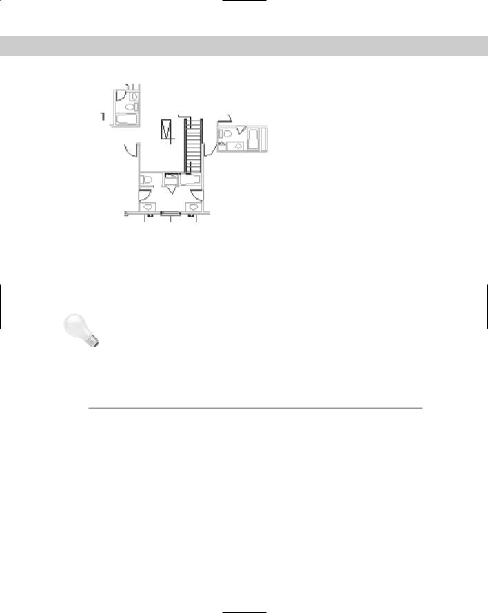
Figure 19-12: The clipped xref.
Managing Xrefs
If you have many xrefs in a drawing, you need a way to keep track of them and their relationships to your drawing. You have several techniques for managing xrefs. The Xref Manager, DesignCenter, and xref notification feature are all tools to help you with this task.
Tip Though it may be obvious, the first principle of managing xrefs is to keep them simple. Overly complex nested configurations are hard to manage, no matter what you do.
The Xref Manager
The Xref Manager dialog box is designed to let you manage xrefs from one place. The Xref Manager has the following features, explained in Table 19-2.
|
Table 19-2: Xref Manager Dialog Box Features |
|
|
Feature |
What It Does |
|
|
Attach |
Opens the Attach Xref dialog box and enables you to specify an xref to attach to your drawing, |
|
as explained earlier in this chapter. |
Detach |
Detaches an xref. The xref is not displayed, and the xref definition is no longer saved in the |
|
drawing. |
Reload |
Reloads the most recent version of the xref. Use this whenever the xref has changed during a |
|
session (because someone else on a networked system has edited the xref drawing) or after |
|
unloading an xref. |
Unload |
Unloads the xref without detaching it. The xref is not displayed, but the xref definition is still |
|
saved in the drawing. You can then use Reload to display the xref again. |
Bind |
Changes the xref to a block. Opens the Bind Xrefs dialog box, which enables you to choose to |
|
either bind or insert the xref. |
Continued
602 Part III Working with Data
|
|
|
Table 19-2: (continued) |
|
|
|
|
|
Feature |
What It Does |
|
|
|
|
|
|
|
Bind |
When creating a block from the xref, this feature changes named |
|
|
|
layers, text styles, dimension styles, and so on (called symbols) |
|
|
|
from the format xref_name|symbol_name to |
|
|
|
drawing_name$#$symbol_name, where # is 0 if the same |
|
|
|
name does not exist in the current drawing or 1 if it already exists. |
|
|
|
In this way, no symbol names are duplicated. This method enables |
|
|
|
you to keep track of where the symbols came from. |
|
|
Insert |
When creating a block from the xref, this feature removes the |
|
|
|
xref_name| portion of symbol names. For example, if a layer of |
|
|
|
that name already exists in your drawing, objects on that layer take |
|
|
|
on the properties of that layer, as defined in your drawing. The |
|
|
|
same applies to text styles, dimension styles, and so on. This |
|
|
|
method removes the complexity that arises with the xref naming of |
|
|
|
these symbols. |
|
Open |
Opens the selected xref in a new drawing window. (AutoCAD only.) |
|
|
Xref Found At |
Specifies where the xref was actually found, which may be different from the saved path. |
|
|
|
You can then click Save Path to save the current path. If the location of an xref is changed |
|
|
|
and is not in the Support Files or Project Files search path, the status of the xref displays |
|
|
|
as Not Found. Use the Browse button to find and open the xref and click Save Path. Click |
|
|
|
OK to automatically reload the xref. |
|
Note |
|
||
You cannot bind or detach nested xrefs without binding the parent xref. |
|||
The Xref Manager is resizable so that you can easily see all of the columns.
Express Tools offer two commands that can help you work with xrefs. XLIST (choose Express Blocks List Xref/Block Properties) lists properties of xrefs and blocks such as object type, layer, object, and linetype. BLOCKTOXREF (choose Express Blocks Convert Block to Xref) replaces a block with an xref (that is, another drawing file).
Xref notification
If an xref is moved or renamed while you have it displayed in an open drawing, you need to reload it. An xref can change if someone else on your network opens and edits it while you’re using it. External Reference Notification offers instant notification if an xref changes.
When you open a drawing with an xref, the status bar displays the Manage Xrefs icon. When an xref changes, a “balloon message” or window appears to notify you, including the name of
Chapter 19 Referencing Other Drawings 603
the drawing and the person who changed it, as shown in Figure 19-13. Click the link to reload the xref (or xrefs). If you want to open the Xref Manager, perhaps to choose which xrefs you want to reload, click the Manage Xrefs icon on the status bar.
New |
You can now reload all xrefs immediately by clicking the link in the notification bubble. You |
Feature |
don’t have to go into the Xref Manager first. |
|
Figure 19-13: If an xref changes, the balloon message appears on the status bar to notify you.
In AutoCAD only, you can control and turn off notification using the XREFNOTIFY system variable.
DesignCenter
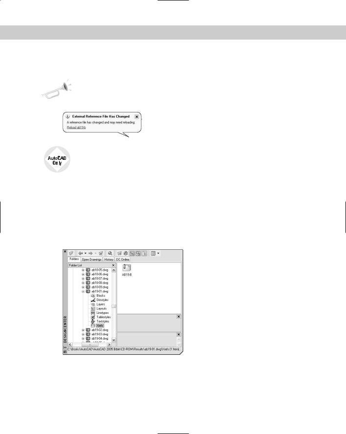
As explained in earlier chapters, you can use the DesignCenter to move named objects, including xrefs, from one drawing to another. To insert an xref from another drawing, choose DesignCenter from the Standard toolbar. Navigate to the drawing and double-click it to open the list of named objects. Double-click Xrefs to see a list of xrefs in the right pane, as shown in Figure 19-14.
Double-click the xref that you want to insert. The External Reference dialog box opens (refer to Figure 19-2) so that you can insert the xref.
Figure 19-14: You can use the DesignCenter to insert xrefs into your drawing.
604 Part III Working with Data
The xref log file
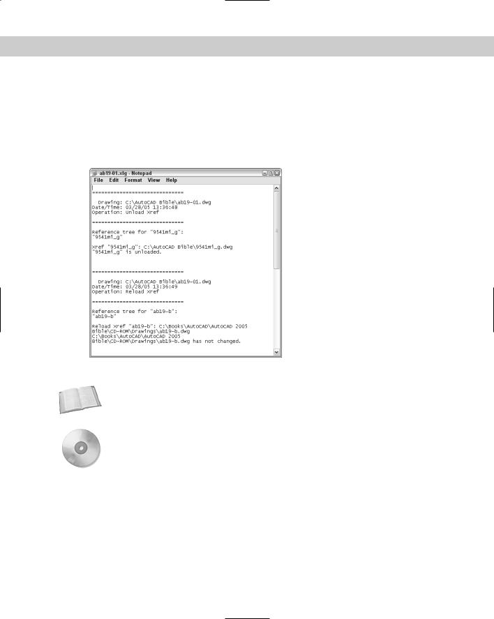
If you set the XREFCTL system variable to 1 (by default, it’s set to 0), a copy of all xref activity for your current drawing is saved in an ASCII text file. You can read the log to troubleshoot problems that may occur. Figure 19-15 shows part of an xref log file. The log file goes in the same folder as your drawing and uses your drawing name with the .xlg file name extension.
This file can become long. Therefore, once in a while, you should delete all or part of the file.
Figure 19-15: An xref log file.
Cross-
Reference
On the
CD-ROM
The Reference Manager is a stand-alone program that manages xrefs, images, fonts, and plot configurations, which are all outside files that are referenced in your drawing. See Chapter 26 for full coverage of the Reference Manager.
The drawing used in the following exercise on managing xrefs, ab19-05.dwg, is in the Results folder on the CD-ROM.
STEPS: Managing Xrefs
1.Use ab19-05.dwg from your AutoCAD Bible folder if you did the previous exercise. Otherwise, open it from the Results folder of the CD-ROM.
2.Save it as ab19-06.dwg in your AutoCAD Bible folder.
3.Do one of the following:
•If you have AutoCAD: Choose Modify Clip Xref. At the Select objects: prompt, pick the xref anywhere. Press Enter. At the Enter clipping option [ON/OFF/ Clipdepth/Delete/generate Polyline/New boundary] <New>: prompt, right-click and choose Delete to delete the clip and restore the entire view of both xrefs.