


24 |
Part I AutoCAD and AutoCAD LT Basics |
STEPS: Saving a Drawing for the First Time
1.The four lines you created earlier in this chapter should still be on your screen. Click Save on the Standard toolbar. The Save Drawing As dialog box opens.
2.Click the Save In drop-down list. If necessary, choose the drive where you created your AutoCAD Bible folder for this book.
3.Double-click the AutoCAD Bible folder.
4.In the File Name text box, select the file name. Type ab01-01 and press Enter (or click Save).
5.Keep your drawing on the screen and go to the next exercise.
AutoCAD saves your drawing under the name ab01-01.dwg. This numbering system will help you organize your drawings from this book and find equivalent drawings on the CD-ROM more easily. It just means that this is the first drawing from Chapter 1 of AutoCAD 2006 and AutoCAD LT 2006 Bible.
Closing a Drawing and Exiting from AutoCAD and AutoCAD LT
|
You can close your drawing and keep AutoCAD or AutoCAD LT open. The simplest way to do |
|
this is to use the drawing Close button just under the application Close button. You can also |
|
choose File Close. |
Tip |
You can choose Window Close All to close all open drawings. If any of the open drawings |
|
have unsaved changes, AutoCAD or AutoCAD LT prompts you to save the changes. If you |
|
have AutoCAD and you installed the Express Tools (see Appendix A for details), you can |
|
choose Express File tools Quick Exit, which closes all open drawings (prompting you to |
|
save if necessary), and then exits the program. |
|
To exit AutoCAD or AutoCAD LT, click the Close (X) box at the top-right corner of your screen. |
|
You can also exit out of AutoCAD or AutoCAD LT by typing quit on the command line and |
|
pressing Enter. Another method is to choose File Exit. |
|
If you’ve made any changes to your drawing since last saving it, AutoCAD or AutoCAD LT asks |
|
you if you want to save your changes. Choose Yes or No as your situation requires. Choosing |
|
Cancel returns you to your drawing. If you have opened more than one drawing to which you |
|
have made changes, you have a chance to save each drawing in turn so that you don’t exit |
|
AutoCAD or AutoCAD LT without saving all the changes you’ve made in your open drawings. |
STEPS: Closing Your Drawing and Exiting AutoCAD or AutoCAD LT
1.Your drawing should still be on your screen. Choose File Close. You now see a gray screen with no drawing. (Repeat this process if you have other drawings open. Save or cancel the changes to these extra open drawings as you like.)
2.Click the Close button in the upper-right corner to exit AutoCAD or AutoCAD LT. The program closes immediately.

Chapter 1 Starting to Draw |
25 |
Summary
In Chapter 1, I explained how to start AutoCAD and AutoCAD LT and create a new drawing. I gave you a tour of the screen and explained how to save a drawing. This chapter provides the basis for all your work in AutoCAD and AutoCAD LT.
In this chapter, you learned the following:
A brief history of AutoCAD and AutoCAD LT
Some of the different disciplines that use AutoCAD and AutoCAD LT
How to start AutoCAD and AutoCAD LT
How to start a new drawing
The user interface and its various sections, including the drawing area, the UCS icon, the crosshairs, the menus and toolbars, the command line, and the status bar
How to start a command from a toolbar
How to start a command from the command line
How to start a command from the menu
How to start a command from a tool palette
How to draw lines
Several ways to pick points on the screen to specify coordinates
How to save a drawing for the first time
How to close a drawing
How to exit AutoCAD and AutoCAD LT
You may have several questions at this point, but “well begun is half done.” The next chapter explains all the ways to start a new drawing as well as how to open an existing drawing.
|
|
|


Opening a Drawing
AutoCAD and AutoCAD LT offer a number of options for opening new and existing drawings. These options create a great deal of
flexibility and save you time as well. You can create complex templates to avoid doing the same basic setup and drawing over and over.
Creating a New Drawing from a Template
A template is a special file that contains settings and often objects (such as a title block). When you use a template as the basis for a new drawing, the drawing takes on all the settings and objects contained in the template. Use templates to avoid re-creating settings and redrawing objects for new drawings. AutoCAD and AutoCAD LT come with many templates that you can use as is or customize. You can also create your own templates.
AutoCAD and AutoCAD LT offer a Startup dialog box that offers Note choices for starting a new drawing as well as opening existing drawings. To display the Startup dialog box whenever you open AutoCAD or AutoCAD LT, choose Tools Options and click the System tab. In the General Options section, choose Show Startup Dialog Box from the Startup drop-down list. Click OK to close the
Options dialog box.
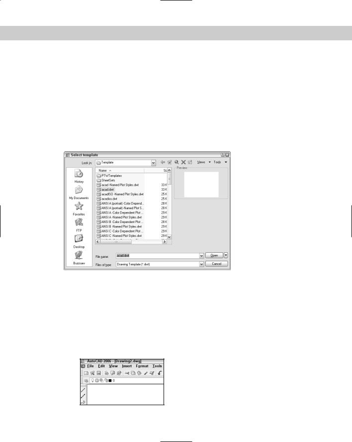
To create a new drawing based on a template, choose File New to open the Select Template dialog box, which lists all the available templates, as shown in Figure 2-1. Click any template to see its preview, if any. Double-click a template to create a new drawing based on that template. Because AutoCAD or AutoCAD LT opens with Drawing1.dwg, the new drawing is named Drawing2.dwg. Subsequent drawings that you create are named Drawing3.dwg and so on. When you save and name your drawing, the original template file is unaffected.
The QNEW command is useful if you always start a new drawing based on the same template. You set a default template and
then click QNew on the Standard toolbar to start a new drawing immediately, based on that default template. To set the default template, follow these steps:
1.Choose Tools Options and click the Files tab.
2.Double-click the Template Settings item.
3.Double-click the Default Template File Name for QNEW item.
C 2H A P T E R
In This Chapter
Creating a new drawing from a template
Opening a drawing with default settings
Opening an existing drawing
Using an existing drawing as a prototype
Saving a drawing with a new name
28 |
Part I AutoCAD and AutoCAD LT Basics |
4.Click the listing under the Default Template File Name for QNEW item (which says None by default).
5.Click Browse to choose the template that you want.
6.Click OK to close the Options dialog box.
You can specify whether this default template uses metric or imperial measurements by setting the MEASUREINIT system variable. (System variables are discussed further in Chapter 5.) On the command line, type measureinit. Enter 0 for imperial units and 1 for metric units.
The default template is acad.dwt for AutoCAD and aclt.dwt for AutoCAD LT. Another default template is acad-Named Plot Styles.dwt or aclt-Named Plot Styles.dwt, which refers to named plot styles. (See Chapter 17.)
Figure 2-1: Choose a template from the Select template dialog box.
STEPS: Opening a Drawing Based on the Default Template
1.Start AutoCAD or AutoCAD LT.
2.Choose File New.
3.From the Select template dialog box, choose acad.dwt (for AutoCAD) or aclt.dwt (for AutoCAD LT) from the list.
4.Click Open. You now have a blank drawing named Drawing2.dwg, as shown in Figure 2-2.
Figure 2-2: When you create a drawing based on a template, AutoCAD or AutoCAD LT creates a drawing called Drawing2.dwg.