

- •Contents
- •Contents at a Glance
- •Acknowledgments
- •Preface
- •Is This Book for You?
- •How This Book Is Organized
- •How to Use This Book
- •Doing the Exercises
- •Conventions Used in This Book
- •What the Icons Mean
- •About the CD-ROM
- •Other Information
- •Contacting the Author
- •Foreword
- •Credits
- •About the Author
- •Summary
- •AutoCAD’s Advantages
- •Comparing AutoCAD and AutoCAD LT
- •Starting AutoCAD and AutoCAD LT
- •Creating a New Drawing
- •Using the AutoCAD and AutoCAD LT Interface
- •Creating a New Folder
- •Using the Interface
- •Saving a Drawing
- •Closing a Drawing and Exiting from AutoCAD and AutoCAD LT
- •Summary
- •Creating a New Drawing from a Template
- •Working with Templates
- •Opening a Drawing with Default Settings
- •Opening an Existing Drawing
- •Using an Existing Drawing as a Prototype
- •Saving a Drawing Under a New Name
- •Summary
- •The Command Line and Dynamic Input
- •Command Techniques
- •Of Mice and Pucks
- •Getting Help
- •Summary
- •Typing Coordinates
- •Displaying Coordinates
- •Picking Coordinates on the Screen
- •Overriding Coordinate Settings
- •Locating Points
- •Summary
- •Choosing Unit Types
- •Drawing Limits
- •Understanding Scales
- •Creating a Title Block
- •Specifying Common Setup Options
- •Customizing with the MVSETUP Command
- •Using the Setup Wizards
- •Summary
- •Using the LINE Command
- •Drawing Rectangles
- •Drawing Polygons
- •Creating Construction Lines
- •Creating Rays
- •Summary
- •Drawing Circles
- •Drawing Arcs
- •Creating Ellipses and Elliptical Arcs
- •Making Donuts
- •Placing Points
- •Summary
- •Panning
- •Using the ZOOM Command
- •Using Aerial View
- •Saving Named Views
- •Working with Tiled Viewports
- •Using Snap Rotation
- •Understanding User Coordinate Systems
- •Creating Isometric Drawings
- •Summary
- •Editing a Drawing
- •Selecting Objects
- •Summary
- •Copying and Moving Objects
- •Resizing Commands
- •Using Construction Commands
- •Creating a Revision Cloud
- •Hiding Objects with a Wipeout
- •Double-Clicking to Edit Objects
- •Grips
- •Editing with the Properties Palette
- •Selection Filters
- •Groups
- •Summary
- •Working with Layers
- •Changing Object Color, Linetype, and Lineweight
- •Working with Linetype Scales
- •Importing Layers and Linetypes from Other Drawings
- •Matching Properties
- •Summary
- •Drawing-Level Information
- •Object-Level Information
- •Measurement Commands
- •AutoCAD’s Calculator
- •Summary
- •Creating Single-Line Text
- •Understanding Text Styles
- •Creating Multiline Text
- •Creating Tables
- •Inserting Fields
- •Managing Text
- •Finding Text in Your Drawing
- •Checking Your Spelling
- •Customizing the spelling dictionary
- •Summary
- •Working with Dimensions
- •Drawing Linear Dimensions
- •Drawing Aligned Dimensions
- •Creating Baseline and Continued Dimensions
- •Dimensioning Arcs and Circles
- •Dimensioning Angles
- •Creating Ordinate Dimensions
- •Drawing Leaders
- •Using Quick Dimension
- •Editing Dimensions
- •Summary
- •Understanding Dimension Styles
- •Defining a New Dimension Style
- •Changing Dimension Styles
- •Creating Geometric Tolerances
- •Summary
- •Creating and Editing Polylines
- •Drawing and Editing Splines
- •Creating Regions
- •Creating Boundaries
- •Creating Hatches
- •Creating and Editing Multilines
- •Creating Dlines
- •Using the SKETCH Command
- •Digitizing Drawings with the TABLET Command
- •Summary
- •Preparing a Drawing for Plotting or Printing
- •Creating a Layout in Paper Space
- •Working with Plot Styles
- •Plotting a Drawing
- •Summary
- •Combining Objects into Blocks
- •Inserting Blocks and Files into Drawings
- •Managing Blocks
- •Creating and Using Dynamic Blocks
- •Using Windows Features
- •Working with Attributes
- •Summary
- •Understanding External References
- •Editing an Xref within Your Drawing
- •Controlling Xref Display
- •Managing Xrefs
- •Summary
- •Preparing for Database Connectivity
- •Connecting to Your Database
- •Linking Data to Drawing Objects
- •Creating Labels
- •Querying with the Query Editor
- •Working with Query Files
- •Summary
- •Working with 3D Coordinates
- •Using Elevation and Thickness
- •Working with the User Coordinate System
- •Summary
- •Working with the Standard Viewpoints
- •Using DDVPOINT
- •Working with the Tripod and Compass
- •Displaying a Quick Plan View
- •Shading Your Drawing
- •Using 3D Orbit
- •Using Tiled Viewports
- •Defining a Perspective View
- •Laying Out 3D Drawings
- •Summary
- •Drawing Surfaces with 3DFACE
- •Drawing Surfaces with PFACE
- •Creating Polygon Meshes with 3DMESH
- •Drawing Standard 3D Shapes
- •Drawing a Revolved Surface
- •Drawing an Extruded Surface
- •Drawing Ruled Surfaces
- •Drawing Edge Surfaces
- •Summary
- •Drawing Standard Shapes
- •Creating Extruded Solids
- •Drawing Revolved Solids
- •Creating Complex Solids
- •Sectioning and Slicing Solids
- •Using Editing Commands in 3D
- •Editing Solids
- •Listing Solid Properties
- •Summary
- •Understanding Rendering
- •Creating Lights
- •Creating Scenes
- •Working with Materials
- •Using Backgrounds
- •Doing the Final Render
- •Summary
- •Accessing Drawing Components with the DesignCenter
- •Accessing Drawing Content with Tool Palettes
- •Setting Standards for Drawings
- •Organizing Your Drawings
- •Working with Sheet Sets
- •Maintaining Security
- •Keeping Track of Referenced Files
- •Handling Errors and Crashes
- •Managing Drawings from Prior Releases
- •Summary
- •Importing and Exporting Other File Formats
- •Working with Raster Images
- •Pasting, Linking, and Embedding Objects
- •Summary
- •Sending Drawings
- •Opening Drawings from the Web
- •Creating Object Hyperlinks
- •Publishing Drawings
- •Summary
- •Working with Customizable Files
- •Creating Keyboard Shortcuts for Commands
- •Customizing Toolbars
- •Customizing Tool Palettes
- •Summary
- •Creating Macros with Script Files
- •Creating Slide Shows
- •Creating Slide Libraries
- •Summary
- •Creating Linetypes
- •Creating Hatch Patterns
- •Summary
- •Creating Shapes
- •Creating Fonts
- •Summary
- •Working with the Customization File
- •Customizing a Menu
- •Summary
- •Introducing Visual LISP
- •Getting Help in Visual LISP
- •Working with AutoLISP Expressions
- •Using AutoLISP on the Command Line
- •Creating AutoLISP Files
- •Summary
- •Creating Variables
- •Working with AutoCAD Commands
- •Working with Lists
- •Setting Conditions
- •Managing Drawing Objects
- •Getting Input from the User
- •Putting on the Finishing Touches
- •Summary
- •Understanding Local and Global Variables
- •Working with Visual LISP ActiveX Functions
- •Debugging Code
- •Summary
- •Starting to Work with VBA
- •Writing VBA Code
- •Getting User Input
- •Creating Dialog Boxes
- •Modifying Objects
- •Debugging and Trapping Errors
- •Moving to Advanced Programming
- •Summary
- •A Final Word
- •Installing AutoCAD and AutoCAD LT
- •Configuring and Using Workspaces
- •Configuring AutoCAD
- •Starting AutoCAD Your Way
- •Configuring a Plotter
- •Discovering AutoCAD and AutoCAD LT
- •Accessing Technical Support
- •Autodesk User Groups
- •Internet Resources
- •System Requirements
- •Using the CD-ROM with Microsoft Windows
- •What’s on the CD-ROM
- •Troubleshooting
- •Index
564 Part III Working with Data
Working with Attributes
Your drawings do not exist in a vacuum. The objects in your drawing represent real objects. These objects have characteristics that you cannot visually represent in a drawing, such as cost, manufacturer, date purchased, and so on. Attributes are labels that are attached to blocks. Using attributes, you can attach labels with pertinent data to blocks. You can then extract the data and import it into a database program or spreadsheet, or even redisplay the data in an AutoCAD table.
Cross- |
You can also access and link to outside databases from within AutoCAD. See Chapter 20 for |
Reference |
more information on external databases. |
|
Attributes can also be used to place text relative to blocks. A common example is to use attributes for completing title block information, such as the drawing name, drawing number, date, scale, revision number, drafter, and so on. In this case, your plan is not to extract the data at all; you just use the attributes to help you precisely place the text in the title block. By inserting fields into these attributes (in AutoCAD only), you can gain another benefit from
attributes: automating the creation of title block text. For more information, see the discussion of fields in Chapter 13.
Attributes have several limitations. For example, they can only be attached to blocks (either regular or dynamic). However, you can create a dummy block that contains only attributes. The database features are also limited. Nevertheless, attributes are quite useful for simple database needs, as well as for placing text.
Defining an attribute creates a template into which you can place values when you insert the block. You define a tag that is equivalent to a field or category in a database. When you insert the block, you’re prompted for the tag’s value. For example, if your tag is COST, the value may be 865.79. This template is called an attribute definition.
Creating attribute definitions
The first procedure when working with attributes is to draw the individual objects that are to make up the block. The exception is when you want to create attributes without creating any other objects in the block. You might do this to extract attributes that apply to the drawing as a whole.
Tip |
If the block already exists, explode it, add the attributes, and then redefine the block. |
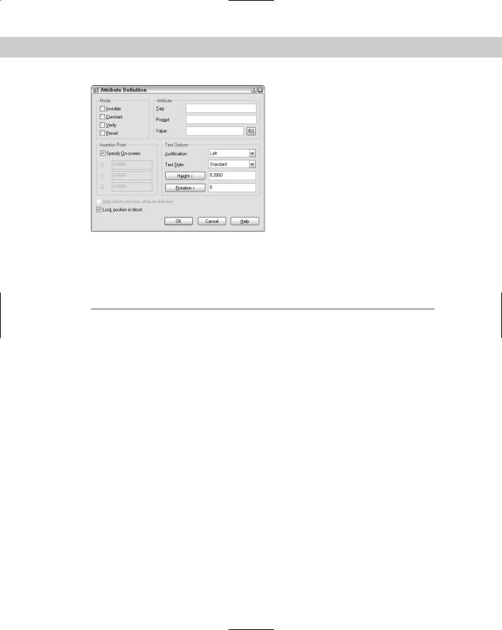
After you have the objects, choose Draw Block Define Attributes to start the ATTDEF command. The Attribute Definition dialog box opens, as shown in Figure 18-31.
Chapter 18 Working with Blocks and Attributes |
565 |
Figure 18-31: The Attribute Definition dialog box.
Mode section
The Mode section of the dialog box sets certain attribute properties, including visibility and default value. These properties are shown in Table 18-5.
|
Table 18-5: Attribute Modes |
|
|
Mode |
Explanation |
|
|
Invisible |
The attribute values that you set are not displayed in the drawing. Use this mode for |
|
attributes that you want to extract into a database but do not want to see in the drawing. |
|
Examples would be model numbers, purchase dates, cost, and so on. Of course, if you’re |
|
using attributes to place text in a drawing, then you want them to be visible. |
Constant |
Sets a constant value for an attribute. The attribute automatically takes the attribute value |
|
that you set (in the Attribute section of the dialog box), and you do not get a prompt for a |
|
value. You might use this for the first three digits of employees’ telephone numbers that |
|
have the same first three digits. You cannot edit constant attribute values. |
Verify |
When you insert an attribute, a prompt appears, asking you to verify the value. Use this |
|
option if you have a preset default. |
Preset |
Automatically inserts a default value that you specify. For example, if the most common |
|
manufacturer of a chair is American Interiors, you can specify this as a preset value. As you |
|
insert the block, this default is inserted for you, and you have to type a value only if it differs |
|
from the default. (You need to insert the attribute with the ATTDIA system variable set to 1 |
|
to get a prompt allowing you to change the value. See the explanation of ATTDIA later in this |
|
chapter.) |
|
|
Attribute section
In the Attribute section of the dialog box, specify the Tag, which is the name of the attribute. You use this tag when you extract the attributes. A tag is equivalent to a field in a database. For example, if you import the data into a spreadsheet the tags would be the column heads. The tag name cannot include spaces or exclamation points (!) and is converted to uppercase letters.
566 Part III Working with Data
The Prompt is simply a plain-English version of the tag. The prompt asks you for the value of the attribute. For example, if the tag is PUR_DATE, you could define the prompt as Date Purchased.
|
The Value is used for setting a default value. You can use this if the value is usually the same. |
|
To insert a field, click the Insert Field button and choose a field from the Field dialog box, as I |
|
explain in Chapter 13. When you insert the block and are prompted for a value, you can either |
|
use the field value or you can change it. |
Tip |
You can use the value to clarify a format that should be followed when entering information. |
|
For example, you could set the value of a date to dd/mm/yy so that users know how to for- |
|
mat the date. |
Text Options section
Use the Text Options settings to format the text. Choose a justification and text style from the drop-down list boxes. When you set the height, be sure to take into account the scale factor. You can also set a rotation angle for the text.
Insertion Point section
In the Insertion Point section, check the Specify On-Screen check box to specify the insertion point in your drawing. Uncheck the same checkbox if you want to pre-specify coordinates.
If you’re using the attributes to place text in a schedule or title block, then the placement is obviously very important. If you’re inserting invisible attributes, simply place them near the block. If you’re creating more than one attribute for a block, place the attribute so that there is room for the other attributes underneath. When you’ve completed the entire dialog box, click OK. If you chose to specify the insertion point in the drawing, specify the point to insert the attribute.
Caution |
If you’re creating an attribute for a table or an electrical symbol, you don’t want the insertion |
|
point to be 0,0. Instead, you want an insertion point near the block. If you uncheck the Specify |
|
On-Screen check box and click OK to close the dialog box, the default insertion point is at 0,0. |
|
If 0,0 isn’t visible on the screen, then you don’t see the attribute — it seems to disappear! You |
|
can choose Undo from the Standard toolbar and create a new attribute in the right location, or |
|
move the attribute as explained in the section on editing attributes later in this chapter. |
New
Feature
After you define one attribute, the Align Below Previous Attribute Definition check box is active. Select this option to line up succeeding attributes under the first one.
The Lock Position in Block check box locks the position of the attribute relative to the block. When you insert a block with attributes, locked attributes do not have their own grip and you can’t move them independently from the block. Unlocked attributes have their own grip that you can use to separately move the attribute. If you want to include an attribute in the selection set of an action in a dynamic block, you must lock that attribute.
Now is the time to confirm that the attribute definitions are the way you want them. You can edit attribute definitions before they’ve been placed into a block in two ways:
Choose Properties on the Standard toolbar, select one attribute definition, and edit all of its properties, such as the tag, value, prompt, and modes. You can also change properties such as the layer, text style, and so on.
Choose Modify Object Text Edit and change the tag, the prompt, and the default (DDEDIT command).

Chapter 18 Working with Blocks and Attributes |
567 |
Tip |
If you’re creating many blocks with similar attributes, you can copy just the attributes, modify |
|
them as just described, place them near other objects, and then create the blocks. This way, |
|
you don’t have to define all of the attributes from scratch. |
Creating the block
|
After you create the objects and their attribute definitions, you generally create a block. Choose |
|
Make Block from the Draw toolbar, and select the objects and the attributes in the block. |
Tip |
If the order of the attribute prompts is important, don’t use a window to select the attributes. |
|
Select them in the order in which you want the prompts to appear. You can then use a crossing |
|
or window box to select the rest of the objects to be included in the block. The order of the |
|
attribute prompts will be important if you’re taking the data for the attributes from a listing, such |
|
as a spreadsheet that you’ve printed out. Inserting the attribute values will be much easier if the |
|
prompts follow the order of the printed document that you’re using. |
Name the block and define the block’s insertion point as you would normally. Generally, you want to check Delete because you have no need for the block with the attribute tags in your drawing.
|
Don’t forget to pay attention to the layer of the attributes, just as you would the layer of the |
|
block objects. The same layer rules apply to attributes as to blocks. |
Note |
If you want to insert the objects and the attributes as a file instead of as a block, you don’t need |
|
to create a block at all. Create a drawing that contains just the objects and its attributes. Use the |
|
BASE command to change the base point of the drawing (usually 0,0) to the desired insertion |
|
point of the block. Then save the drawing. When you insert the drawing, you are prompted for |
|
the attributes, as usual. Use this technique for blocks and attributes that you use for more than |
|
one drawing, such as a title block. |
After you create the block, you cannot edit the attributes in the Properties palette. I cover other techniques for editing attributes later in this chapter.
On the |
The drawing that you need for the following exercise on creating attributes, ab18-h.dwg, is |
CD-ROM |
in the Drawings folder on the CD-ROM. |
STEPS: Creating Attributes
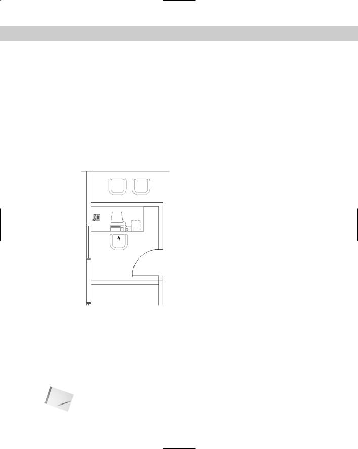
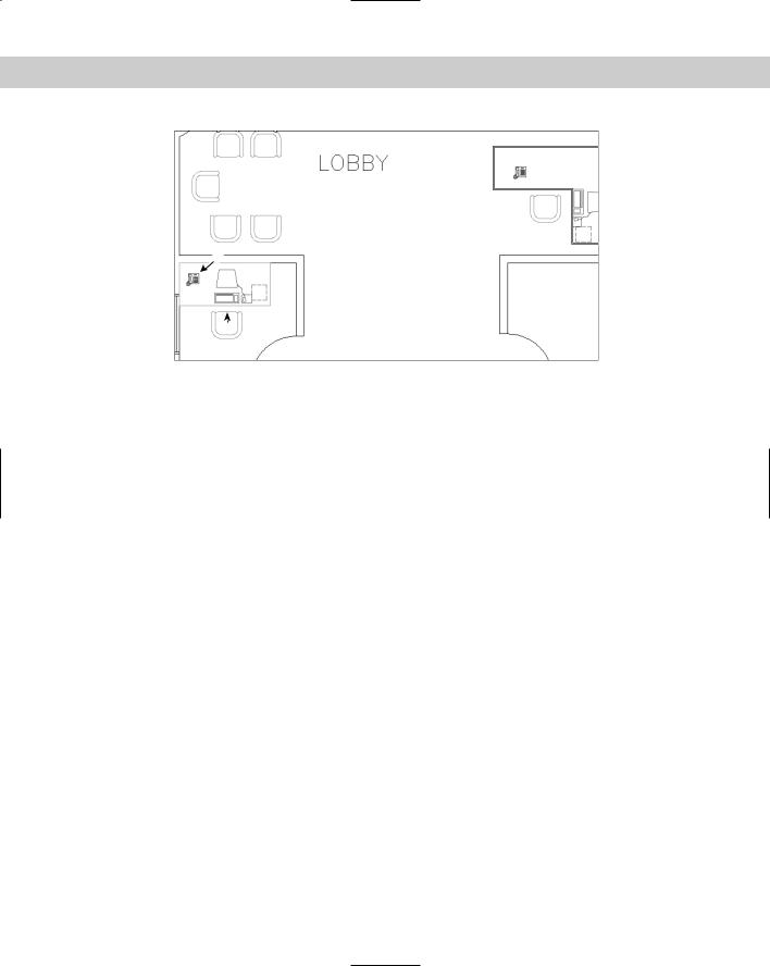
1.Open ab18-h.dwg from the CD-ROM. This is a plan of an office building zoomed in to one office. A file containing one set of office furniture has been inserted, as shown in Figure 18-32.
2.Save the drawing as ab18-08.dwg in your AutoCAD Bible folder.
3.Choose Explode from the Modify toolbar, select the furniture in the office, and press Enter. This block has nested blocks. Choose the chair and explode it again to get its component objects.
4.Choose Draw Block Define Attributes. In the Attribute Definition dialog box, check Invisible in the Mode section.
568 Part III Working with Data
5.In the Attribute section, enter the following:
Tag: mfr
Prompt: Manufacturer
Value: American Office Furniture
6.Leave the Text Options as they are. Make sure that the Specify On-Screen check box is checked and click OK. Pick point 1 in Figure 18-32.
7.Repeat the ATTDEF command. Check the Align below previous attribute definition check box. Enter the following:
Tag: pur_date
Prompt: Date purchased
Value: 3/91
8.Click OK.
2
1
Figure 18-32: An office with a set of office furniture.
9.Choose Make Block from the Draw toolbar. In the Name text box, type armchair. Click Select Objects. Select the entire chair along with the two attributes. End selection. The dialog box shows that 18 objects are selected. Choose Pick Point. Use the Endpoint object snap to choose 2 as the base point. Check Delete. Click OK.
10.A message asks whether you want to redefine the block because there is already a block definition with the same name in the drawing. Choose Yes.
11.Save your drawing. If you’re continuing on to the next exercise, leave the drawing open.
Note |
Redefining a block updates only block geometry, not attributes. Therefore, if you add attribute |
|
definitions to a block, only new blocks that you’ll insert include the attributes. Existing blocks |
|
don’t gain these new attribute definitions. To update existing blocks with their current attribute |
|
definitions, use the ATTSYNC command (AutoCAD only). |
Chapter 18 Working with Blocks and Attributes |
569 |
Inserting blocks with attributes
After you define a block with attributes, you insert it as you would any block. Your drawing automatically detects the existence of the attributes and prompts you for their values.
Note |
You can insert attributes either in a dialog box or on the command line. By default, you insert |
|
them on the command line. To use a dialog box, set the system variable ATTDIA to 1. You |
|
would use the command line to automate the insertion of attributes using an AutoLISP rou- |
|
tine, menu item, or script file. When you use a dialog box, the Verify and Constant modes are |
|
not used. To skip all of the prompts and automatically use default values that you have set, set |
|
the ATTREQ system variable to 0. |
On the |
The drawing that you need for the following exercise on inserting blocks with attributes, |
CD-ROM |
ab18-08.dwg, is in your AutoCAD Bible folder if you did the previous exercise. Otherwise, |
|
you can find it in the Results folder on the CD-ROM. |
STEPS: Inserting Blocks with Attributes
1.Use ab18-08.dwg if you have it open from the previous exercise. Otherwise, open it from the Results folder of the CD-ROM.
2.Save the drawing as ab18-09.dwg in your AutoCAD Bible folder.
3.Type attdia . If it’s currently set to 0, type 1 .
4.Choose Insert Block from the Draw toolbar. Chose ARMCHAIR from the Name drop-down list. Verify that the Specify On-screen option is checked only for Insertion Point, and click OK.
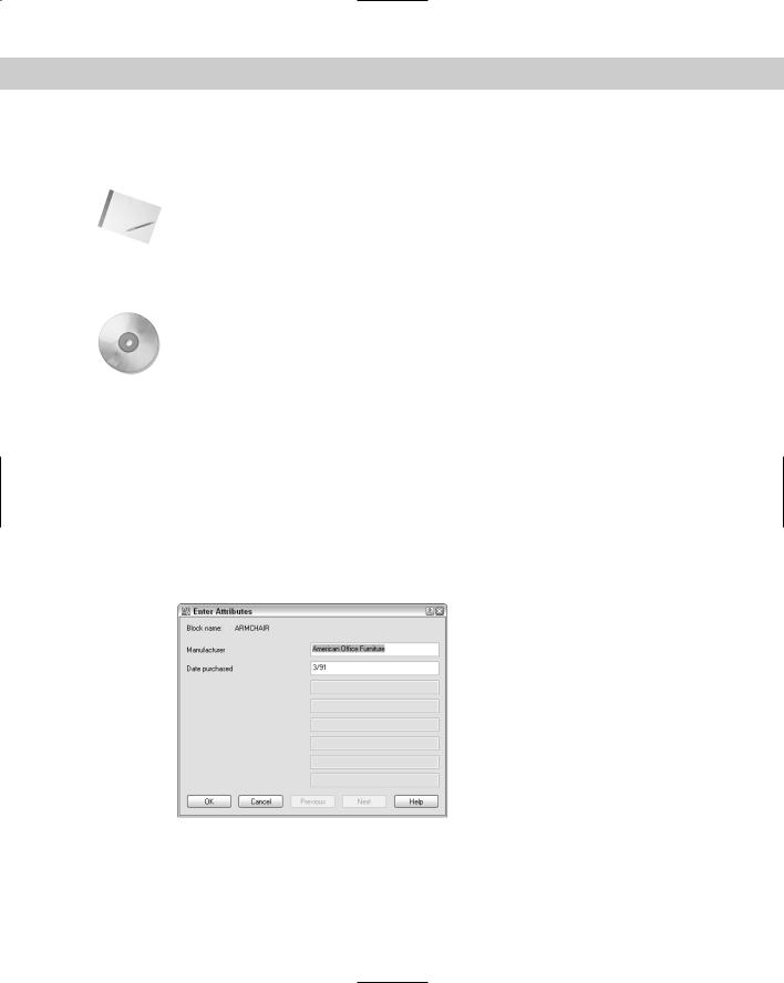
5.Pick a point in front of the desk (turn off OSNAP if necessary) to insert the armchair, and open the Enter Attributes dialog box, as shown in Figure 18-33. The values that were entered when the attributes were defined are displayed, but you can change them.
Figure 18-33: The Enter Attributes dialog box.
6.The default values exist because most of the furniture was purchased at one time when the office was opened. However, let’s assume that this chair was purchased recently. Change the purchase date to 3/05. Click OK. Because the attributes are invisible, you see only the chair, but the values do exist in the drawing database.
7.Save the drawing.
570 Part III Working with Data
Editing attributes
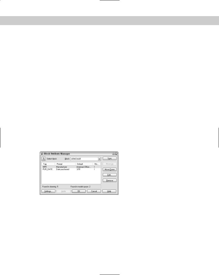
You can edit the properties of the attribute tags before you create the block, by using the Properties palette or DDEDIT (choose Modify Object Text Edit). If you have AutoCAD, after you create the block, use the Block Attribute Manager. The Block Attribute Manager manages all properties of block attributes in one place. Use the Block Attribute Manager and its Edit Attribute dialog box to edit any aspect of block attributes. If you have AutoCAD LT, use the Edit Attributes dialog box (ATTEDIT command).
Editing attribute properties in AutoCAD
After you insert a block and give values to its attributes, you can modify the following:
Attribute prompt order
Tag and prompt names
Attribute visibility
Text options
Properties (layer, linetype, color, lineweight, and plot style)
Attribute value
After you make your changes, you can update all of the blocks in your drawing to reflect the changes.
Choose Modify Object Attribute Block Attribute Manager to start the BATTMAN command and open the Block Attribute Manager, as shown in Figure 18-34.
Figure 18-34: The Block Attribute Manager.
From the Block drop-down list in the Block Attribute Manager, choose the block whose attribute values you want to change. You can also click Select block to select the block in your drawing. Use the Block Attribute Manager to:
Change the order of the attribute prompts when you insert a block with attributes.
Choose any attribute from the list in the Block Attribute Manager, and click Move Down or Move Up. Continue to use this procedure until you have the order that you want.
Delete an attribute. Choose it and click Remove.
Change which attribute properties are listed in the Block Attribute Manager. Click Settings. In the Settings dialog box, click all of the properties that you want to see listed. For example, you can include columns for layer, style (text style), and color. Click OK.
Chapter 18 Working with Blocks and Attributes |
571 |
Tip |
When you add properties to the listing in the Block Attribute Manager, resize the dialog box |
|
so that you can see all of the columns. |
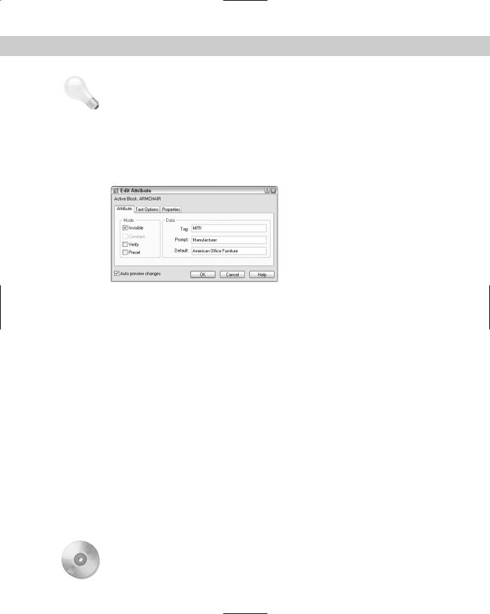
Edit the attributes, including prompt, default, text display, and properties. Click Edit to open the Edit Attribute dialog box, as shown in Figure 18-35.
Update all of the blocks in your drawing to reflect the changes that you’ve made.
Click Sync. Usually you do this after using the Edit Attribute dialog box. Because changes such as attribute order and mode affect only new insertions of the block, this update brings existing blocks into concordance with new blocks.
Figure 18-35: The Edit Attribute dialog box.
Use the Edit Attribute dialog box to edit all of the properties of individual attributes. This dialog box has three tabs:
Attribute: Allows you to change the mode and attribute properties. For example, in the Mode section, you can change the visibility of attributes. In the Data section, you can change the tag, prompt, and default. You can right-click the Default text box and choose Insert Field to use a field. (See Chapter 13 for a discussion of fields.)
Text Options: Allows you to change text style, height, justification, and so on.
Properties: Allows you to change attribute layer, color, linetype, and so on.
After you finish making changes, click OK in the Edit Attribute dialog box to return to the Block Attribute Manager. Click OK to return to your drawing.
When you create invisible attributes, you can’t edit them because you can’t select them.
The ATTDISP command controls attribute visibility globally, for all attributes in your drawing. Choose View Display Attribute Display and choose one of the following options. The currently active option is checked on the menu.
Normal: Attributes that were created as visible are visible. Attributes that were created as invisible are invisible. This is the default option.
On: All attributes are visible.
Off: All attributes are invisible.
Changing the current option causes your drawing to regenerate.
On the |
Insrot is a program that inserts a block at a specified rotation but keeps the attributes |
CD-ROM |
horizontal. Look in \Software\Chap18\Insrot. Attstrip removes all attributes from |
|
selected blocks. Look in \Software\Chap18\attstrip. |
572 Part III Working with Data
You may need to change the values of an attribute. Perhaps you entered the wrong purchase date or a part number has changed. Choose Modify Object Attribute Single to start the EATTEDIT command, and select the block containing the attributes that you want to change. You see the Enhanced Attribute Editor, as shown in Figure 18-36.
Figure 18-36: The Enhanced Attribute Editor.
As you can see, the Enhanced Attribute Editor is similar to the Edit Attribute dialog box. For example, it has the same three tabs. However, the Attribute tab enables you to change attribute values, something that you can’t do in the Edit Attribute dialog box. To change an attribute’s value, select it and type a new value in the Value text box. In AutoCAD only, you can right-click the Value text box and choose Insert Field to use a field. (See Chapter 13 for more about fields.)
The Text Options and Properties tabs of the Enhanced Attribute Editor are the same as in the Edit Attributes dialog box.
Caution |
If you explode a block with attribute values, you lose the attribute values. |
Editing attribute properties in AutoCAD and AutoCAD LT
In both AutoCAD and AutoCAD LT, you can change attribute values using the ATTEDIT command to open the Edit Attributes dialog box, as shown in Figure 18-37.
Figure 18-37: The Edit Attributes dialog box.

Chapter 18 Working with Blocks and Attributes |
573 |
If a block has a number of attributes and you want to change them all in order, this dialog box makes it easy to go through all of the attributes quickly. Press Tab to go to the next attribute.
In AutoCAD LT, one way to change attribute properties is to explode the block and doubleclick the attribute. This starts the DDEDIT command and opens the Edit Attribute Definition dialog box, where you can change the tag, prompt, and default value. You can then redefine the block. This method works in AutoCAD, but is not necessary if you use the Block Attribute Manager, as explained in the previous section.
To edit attributes on the command line, type -attedit. At the Edit attributes one at a time? [Yes/No] <Y>: prompt, select the Yes option. This command then prompts you for changes in attribute values and properties, such as position, text style, color, and so on.
Making global changes in attributes
In both AutoCAD and AutoCAD LT, you can also use the -ATTEDIT command on the command line to make global changes. If you answer No to the Edit attributes one at a time? [Yes/No] <Y>: prompt, you can make global changes to attribute values. For example, you can change all instances of A- in your part numbers to B-. You can even change invisible attribute values.
To use -ATTEDIT to make global changes, follow these steps:
1.Choose Modify Object Attribute Global.
2.At the Edit attributes one at a time? [Yes/No] <Y>: prompt, type n .
3.At the Edit only attributes visible on screen? [Yes/No] <Y>: prompt, answer y or n , as desired. If you answer n to edit invisible attributes, then you must know the attribute text string that you want to change because it is invisible.
4.At the Enter block name specification <*>: prompt, you can type a block name to limit the changes to one block, or press Enter to include any block.
5.At the Enter attribute tag specification <*>: prompt, you can type a tag to limit the changes to one tag type, or press Enter to include any tag.
6.At the Enter attribute value specification <*>: prompt, you can type a value to limit the changes to one value, or press Enter to include any value.
7.If you chose to edit only attributes that are visible on-screen, you see the Select Attributes: prompt. (If not, skip to Step 8.) Pick each attribute that you want to modify, or use a window. Press Enter to end selection. If you include other objects or blocks that do not fit the block name, attribute tag, or attribute value specifications that you made, then these other objects are not selected. The command line informs you of how many attributes were selected.
8.At the Enter string to change: prompt, type the text string (any consecutive text) that you want to change.
9.At the Enter new string: prompt, type the text string that will replace the old string.
If you chose to edit attributes that are not visible on the screen, the drawing regenerates, and the command line lists the changes that it made.
Redefining attributes
You can redefine a block with attributes to include different objects and attributes, using the ATTREDEF command. Redefining a block lets you add or delete attributes or redefine a block that contains attributes. Follow these steps:
574 Part III Working with Data
AutoCAD LT does not include this feature. Instead, explode the block and start from scratch. You can also use the DDEDIT command to change attributes after you explode a block.
1.Explode one of the blocks with attributes. If there are nested blocks that you want to change, explode them, too.
2.If you want to add attributes, define and place them. Delete unwanted attributes. Make any other changes that you want to the objects.
3.Type attredef .
4.At the Enter name of Block you wish to redefine: prompt, type the name of the block.
5.At the Select objects for new Block...: prompt, select the objects and the attributes that you want to include. Do not include any existing attributes that you want to delete.
6.At the Specify insertion base point of new Block: prompt, pick the base point for the block.
Here’s how your drawing handles the changes:
On the
CD-ROM
If you created new attributes, the command places them for all existing blocks and gives them their default values.
Any attributes that you did not change retain their old values for all existing blocks.
Any attributes that you did not include in the new block definition are deleted from existing blocks.
The drawing that you need for the following exercise on editing attributes, ab18-i.dwg, is in the Drawings folder on the CD-ROM.
STEPS: Editing Attributes
1.Open ab18-i.dwg from the CD-ROM.
2.Save the file as ab18-10.dwg in your AutoCAD Bible folder. This is a portion of an office building plan layout, as shown in Figure 18-38.
3.Choose Modify Object Attribute Single.
•If you have AutoCAD: At the Select a block: prompt, In the Value text box of the Enhanced Attribute Editor, change the date purchased to 4/97.
•If you have AutoCAD LT: At the Select block reference: prompt, pick the chair at 1 in Figure 18-38. In the Edit Attributes dialog box, change the date purchased to 4/97.
Notice that the manufacturer is American Office Furniture. Because these attributes are invisible, you can’t see the result in the drawing. Click OK.
4.To see the attributes, choose View Display Attribute Display On. You can now see the attributes for the chair, as well as nearby attributes for the desk. To turn off the attributes, repeat the process, this time choosing the Normal option.
Chapter 18 Working with Blocks and Attributes |
575 |
3
4
2  1
1
Figure 18-38: An office building plan layout.
5.Choose Modify Object Attribute Global. Follow the prompts:
Edit attributes one at a time? [Yes/No] <Y>: n
Performing global editing of attribute values.
Edit only attributes visible on screen? [Yes/No] <Y>: n
Drawing must be regenerated afterwards.
Enter block name specification <*>: armchair Enter attribute tag specification <*>: Enter attribute value specification <*>:
6 attributes selected.
Enter string to change: American
Enter new string: Acme (Press F2 to hide the text window if it is open.)
6.Choose Explode from the Modify toolbar and select the chair at 1 in Figure 18-38. Press Enter to end selection. The attributes reappear, but without their values. Choose Draw Block Define Attributes. Create an invisible attribute with a tag and prompt of Color, and a value of Dusty Blue. Click OK and pick an insertion point underneath the other two attributes of the armchair. (You’ll need to pan down a little. Exact placement is not important.) Choose OK.
7.To redefine the block, do one of the following:
If you have AutoCAD: Type attredef . Follow the prompts:
Enter name of Block you wish to redefine: armchair
Select objects for new Block...Select objects: Use a window to select the chair and the three attributes. Press Enter to end selection.
Specify insertion base point of new Block: Use an endpoint object snap to pick the endpoint at 2.
If you have AutoCAD LT: Choose Make Block from the Draw toolbar. In the Name text box, enter armchair. Click the Pick Point button and use an endpoint object snap to pick the endpoint at 2. Click the Select Objects button and select all of the objects that make up the chair, and then the three attributes. Press Enter to end selection. In the Objects section, choose the Delete option. Click OK. Click Yes to redefine the block.
The armchair block disappears.

576 Part III Working with Data
8.Choose Insert Block. In the Insert dialog box, choose armchair from the Name dropdown list. With Specify On-screen checked only for Insertion Point, click OK. Insert the chair at 2. In the Enter Attributes dialog box, click OK to accept the values, or press Enter to accept the values on the command line.
9.AutoCAD only: To verify that your drawing has redefined the block elsewhere, choose Modify Object Attribute Single. Select the block at 3. Notice that the Color tag has been added with a value of Dusty Blue. Click OK to accept the values. (In AutoCAD LT, the new attribute appears only in the block that you redefined, and new blocks that you insert.)
10.Use Zoom Window to zoom in closely to the telephone at 4 in Figure 18-38. The telephone has a visible attribute of the phone number. The number is so small that it cannot usually be seen, and so does not interfere with the drawing.
11.To modify the properties of this attribute, do one of the following:
If you have AutoCAD: Choose Modify Object Attribute Block Attribute Manager. From the Block drop-down list, choose Phone. Click Edit. On the Attribute tab of the Edit Attribute dialog box, change the prompt to Extension. On the Text Options tab, choose Fit from the Justification drop-down list. On the Properties tab, choose Blue (if you’re using a white background) or Cyan (if you’re using a black background) from
the Color drop-down list. Click OK twice to return to your drawing. The text of the phone extension is now blue and fills up the entire rectangle on the phone.
If you have AutoCAD LT: Choose Modify Object Attribute Global. Follow the prompts:
Edit attributes one at a time? [Yes/No] <Y>: Enter block name specification <*>:
Enter attribute tag specification <*>: Enter attribute value specification <*>:
Select Attributes: Select the phone number.
Select Attributes: 1 attributes selected.
Enter an option [Value/Position/Height/Angle/Style/Layer/Color/Next] <N>: c
Enter new color <BYLAYER>: blue (or enter cyan if you are using a black screen).
Enter an option [Value/Position/Height/Angle/Style/Layer/Color/Next] <N>:
The phone number is now blue.
12.Choose Zoom Previous from the Standard toolbar. Save the drawing.
The Express Tools command BURST (choose Express Blocks Explode Attributes to Text) converts attributes to text. Apply the ATTOUT and ATTIN commands (choose Express Blocks Export). Attribute Information and Import Attribute Information work together to enable you to edit attributes in another program. For example, ATTOUT creates a tab-delimited file that you can open in Notepad or Excel. When you use ATTIN, existing blocks are updated with the new attribute information.
Chapter 18 Working with Blocks and Attributes |
577 |
Extracting a database from attributes
New
Feature
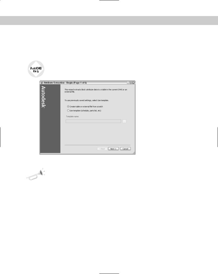
After you insert all of your blocks and attributes, you can extract the data using the Attribute Extraction Wizard, shown in Figure 18-39. To start the wizard, choose Tools Attribute Extraction.
The Attribute Extraction Wizard exists only in AutoCAD. For AutoCAD LT, you need to use the method that I explain in the sidebar, “Creating a Template File the Old-Fashioned Way.”
Figure 18-39: The first screen of the Attribute Extraction
Wizard.
The Attribute Extraction Wizard has been updated for AutoCAD 2006 to enable you to extract attributes to an AutoCAD table that you place in your drawing.
On the Begin screen of the wizard, choose one of two options:
Create table or external file from scratch: Choose this option if you don’t have a BLK file, which is a template that you create in the Attribute Extraction Wizard. In this case, you’ll define the fields that you want to use.
Use template (schedule, parts, list, etc.): Choose this option if you previously saved a BLK file, which is a template that you created previously in the Attribute Extraction Wizard. If you choose this option, browse to the BLK file and select it.
In either case, click Next. The following instructions assume that you chose the first option, which requires more steps.
On the Select Drawings screen, choose from where you want to extract attributes. Most often, you want to keep the default selection of Current Drawing. However, you can select objects (blocks) within the drawing, or choose an entirely different drawing or drawing set.
Click Additional Settings to specify some block and block-count settings. You can choose to include nested blocks, include blocks in xrefs, and include xrefs as blocks in the block count. (Xrefs are covered in Chapter 19.) When counting blocks, you can include all blocks or only blocks in model space.
578 Part III Working with Data
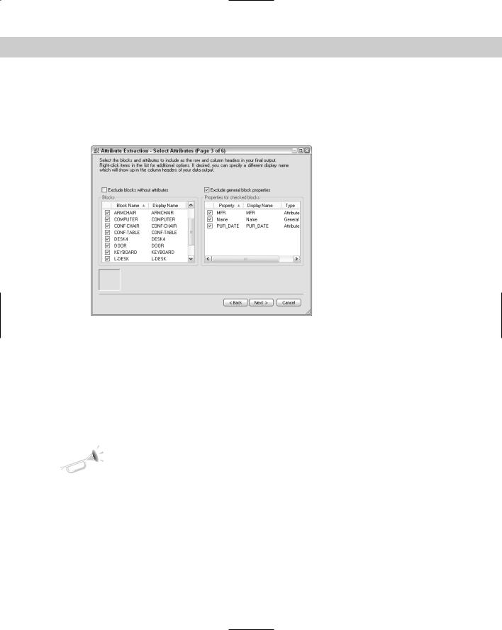
Click Next to go to the next screen, Select Attributes, as shown in Figure 18-40. Here you choose the blocks with which you want to work, along with their attributes. You can also choose from a number of standard data-extraction fields, such as the coordinates, scale, and layer of the block. These fields are described in the table in the sidebar “Creating a Template File the OldFashioned Way.”
Figure 18-40: The Select Attributes screen of the Attribute
Extraction Wizard.
First, select the blocks with which you want to work. Right-click and choose Uncheck All or Check All if you want to check or uncheck only one or two from the list. You can include general block properties, such as layer, color, X position, and Y position. To view these properties, uncheck the Exclude General Block Properties option check box. If you want to extract only the attributes that you’ve created, make sure that this check box is checked. Click Next when you’re done.
On the Finalize Output screen, you can view the extracted attributes. You can sort the list according to any column by clicking that column. You can also change the order of the columns by dragging them to the left or right. Click Full Preview to see the data in its final form.
New |
You can now export directly to an AutoCAD table. |
Feature |
|
In the Extract Attribute Data To section, check the output that you want to create. You can output to an AutoCAD table, an external file, or both. You can create the following types of files:
CSV (Comma Delimited) (*.csv): Lists its attribute values with a comma between each value. Most spreadsheets and databases can import this format.
Tab Delimited File (*.txt): This is like a CSV file, except that there is a tab between each attribute value.
Microsoft Excel (*.xls): Creates an Excel spreadsheet.
Microsoft Access Database (*.mdb): Creates an Access database file.
To continue, click Next.

Chapter 18 Working with Blocks and Attributes |
579 |
If you choose to export to a table, on the next screen, you can choose a table title and style. If you don’t have a table style (except the default, Standard), click the Ellipsis (. . .) button to open the Table Style dialog box. Click New to create a new table style. When you have chosen a table title and style, click Next.
The Finish screen lets you create and save a template file. You can then use the template in the future to ensure that you extract attributes with the same settings. If you don’t want to save a template, click Finish. To save a template, click Save Template to open the Save As dialog box. Here you can specify the name and location of the template. The file name extension is .blk. Click Save. Then click Finish.
Note |
Don’t confuse the template file used for extracting attributes with the template file (with a file |
|
name extension of .dwt) that you use as a basis for opening a drawing. Keep in mind that you |
|
can’t use ASCII template files with the Attribute Extraction Wizard; you can only use the .blk |
|
templates that you create with the wizard. |
If you chose to create a table, you see the table at the cursor, and the Specify insertion point: prompt. Specify a location to place the table. If you chose to create an external file, you see a message on the command line that looks something like the following:
External file “C:\AutoCAD Bible\Ch18\ab18-08.xls” was successfully created.
Note |
If you have AutoCAD LT, skip this exercise, and use the following exercise instead. |
Creating a Template File the Old-Fashioned Way
With AutoCAD’s Attribute Extraction Wizard, you don’t need to create templates “by hand.” You can still create templates on your own, but you must use the ATTEXT command to extract them. If you have AutoCAD LT, you must use the following method.
Create the template file in a text editor such as Windows Notepad. The template file contains two columns. The first is the name of the attribute tag. The second is a format code that specifies whether the data is a character or number, how many spaces to allow for the data, and the decimal precision to use. The format code uses the following syntax:
TWWWPPP
where T is the data type (either N for numeral or C for character), WWW is the width, including commas and decimal points, and PPP is the precision. For integers and all character data, use 000 as the precision.
For example, you would use N006002 for costs that range up to $999.99. The N means that the data is numeric, 006 means that you will have up to six spaces, including the decimal point, and the 002 means that you have precision to two decimal places.
In addition to information from your attributes, you can extract certain standard fields from the drawing’s database. The table that follows lists these fields and their formatting.
Continued

580 Part III Working with Data
Continued
The block number is a number given to the blocks that you select when extracting the data. The block handle is a unique alphanumeric code given to all objects in your drawing; to see a block’s handle, use the LIST command and select the block. Handles are used for referring to objects when you write AutoLISP or other programming code. The extrusion data is used for 3D drawing. See Chapter 24 for an explanation of extrusion.
Field |
Format |
Explanation |
|
|
|
BL: LEVEL |
NWWW000 |
Block nesting level |
BL: NAME |
CWWW000 |
Block name |
BL: X |
NWWWPPP |
X coordinate of block insertion point |
BL: Y |
NWWWPPP |
Y coordinate of block insertion point |
BL: Z |
NWWWPPP |
Z coordinate of block insertion point |
BL: NUMBER |
NWWW000 |
Block counter |
BL: HANDLE |
CWWW000 |
Block handle |
BL: LAYER |
CWWW000 |
Block insertion layer name |
BL: ORIENT |
NWWWPPP |
Block rotation angle |
BL: XSCALE |
NWWWPPP |
X scale factor |
BL: YSCALE |
NWWWPPP |
Y scale factor |
BL: ZSCALE |
NWWWPPP |
Z scale factor |
BL: XEXTRUDE |
NWWWPPP |
X component of Block’s extrusion direction |
BL: YEXTRUDE |
NWWWPPP |
Y component of Block’s extrusion direction |
BL: ZEXTRUDE |
NWWWPPP |
Z component of Block’s extrusion direction |
|
|
|
Template files are quite finicky. Here are the rules that you should follow:
You must include at least one attribute tag in your template.
Each row must be unique — don’t include the same attribute more than once.
You must use only spaces to line up the two columns — no tabs! (Lining up the two columns just makes it easier to read.)
End each line with a return, including the last line.
Don’t put any extra spaces after any line, or any extra returns after the last return that is after the last line of text.
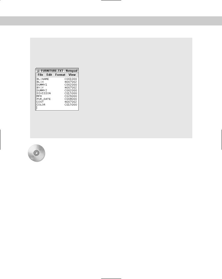
Each row in the template file becomes a column in the resulting output file. If you choose spacedelimited form for the output file, then spaces do not automatically appear between the columns; as a result, the output files are hard to read. You can place dummy rows in the template file for the purpose of creating spaces in the resulting columns. A typical dummy row looks like this:
DUMMY1 C002000
Chapter 18 Working with Blocks and Attributes |
581 |
Because each row must be unique, if you need another dummy row, call it DUMMY2. This row creates a blank column of two spaces in the output file.
The figure shows a typical template file that tracks the company division, as well as the furniture’s manufacturer, purchase date, cost, and color.
After you’re done, save the file with a file name extension of .txt. To use the file, you must use the ATTEXT command, which opens the Attribute Extraction dialog box. In this dialog box, click Template File and choose the file that you created. Choose the file format that you want to create, and name the output file. Then click OK to extract the attributes.
On the |
The drawing that you need for the following exercise on extracting attribute data in AutoCAD, |
CD-ROM |
ab18-j.dwg, is in the Drawings folder on the CD-ROM. |
STEPS: Extracting Attribute Data in AutoCAD
1.Open ab18-j.dwg from the CD-ROM. This is the same office building plan that you used earlier in this chapter, shown in Figure 18-41. Save the drawing as ab18-11.dwg in your AutoCAD Bible folder. Change the current layer to 0.
2.Choose Tools Attribute Extraction to open the Attribute Extraction Wizard.
3.The Create Table or External File from Scratch option should be selected on the Begin screen. Click Next.
4.On the next screen, the Current Drawing option should be selected. Click Next.
5.On the Select Attributes screen, right-click on the Blocks list and choose Uncheck All. Then check Armchair. On the right side, uncheck the Exclude General Block Properties check box. In the Properties for Checked Blocks list, check the following:
•COLOR
•MFR
•Position X
•Position Y
•PUR_DATE
•Rotation
582 Part III Working with Data
8
67
5
43 2
1
Figure 18-41: The office building plan includes several blocks of armchairs with invisible attributes.
6.Click Next.
7.You should see the data with each attribute in its own column. Click Full Preview to see all of the data, and then close the Preview window.
8.In the Extract Attribute Data To section, check both check boxes: AutoCAD Table and External File. Click the Ellipsis button next to the External File text box. In the Save As dialog box, navigate to your AutoCAD Bible folder. From the Files of Type drop-down list, choose *.csv. Leave the default name (ab18-11.csv) and click Save. (If you have Microsoft Excel or Access, you can choose the appropriate file type for one of those applications.) Click Next.
9.On the Table Style screen, type Armchair Data in the Enter a Title for Your Table text box. The table style should be set to Office. Click Next.
10.On the Finish screen, click Save Template. Save the file as ab18-11.blk in your AutoCAD Bible folder. Click Save. Click Finish in the wizard.
11.At the warning message that explains that manual edits to the table will be lost when you refresh the data in the table and asks if you want to continue inserting the table, click Yes.
12.On the command line, you see a message that the CSV file was successfully created. You also see a Specify insertion point: prompt for the table. Pick a point to the right of the floor plan to insert the table.
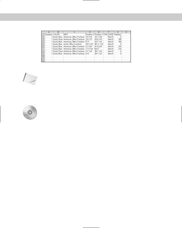
13.To view the CSV file, open Windows Explorer and double-click ab18-11.csv in your AutoCAD Bible folder. It should open in Microsoft Excel or another application that opens CSV files on your system. The data should look like Figure 18-42.
14.Save your drawing.
Chapter 18 Working with Blocks and Attributes |
583 |
Note
On the
CD-ROM
Figure 18-42: The output file that results from extracting the attributes in the office building plan.
If you export attributes in tab-delimited format, you can open the Multiline Text Editor and click Import Text to import the output file into your drawing. You can also open the output file, copy it to the Clipboard, and paste it into your drawing. The Import Text method enables you to format the text as you would any multiline text, but may take some experimenting to align the columns. You cannot format the text that you import using the Clipboard method, but it’s nicely lined up in columns. Using the table option as you did in the exercise provides the best combination of formatting options.
The files that you need for the following exercise on extracting attribute data in AutoCAD LT, ab18-j.dwg and ab18-j.txt, are in the Drawings folder on the CD-ROM.
STEPS: Extracting Attribute Data in AutoCAD LT
1.Open ab18-j.dwg from the CD-ROM. This is the same office building plan that you used earlier in this chapter, shown in Figure 18-41.
2.Type attext to open the Attribute Extraction dialog box.
3.Choose the Space Delimited File (SDF) option.
4.Choose Select Objects. Pick the eight armchairs in the lobby and the three offices. Press Enter to end selection.
5.Choose Template File. In the Template File dialog box, navigate to and choose ab18- j.txt from the CD-ROM. Click Open.
6.Choose Output File. In the Output File dialog box, choose your AutoCAD Bible folder and name the file ab18-11.txt. Click Save.
7.Click OK. The command line displays the message 8 records in extract file.
8.To view the output file, choose Start Run from the Windows task bar. Type Notepad and click Run. In Notepad, choose File Open, and locate the ab18-11.txt file in your AutoCAD Bible folder. Click Open.
This exercise shows how to extract attributes using space-delimited format. This format is easier to import into AutoCAD by copying and pasting. However, comma-delimited format is easier to import into most spreadsheet programs.