

- •Contents
- •Contents at a Glance
- •Acknowledgments
- •Preface
- •Is This Book for You?
- •How This Book Is Organized
- •How to Use This Book
- •Doing the Exercises
- •Conventions Used in This Book
- •What the Icons Mean
- •About the CD-ROM
- •Other Information
- •Contacting the Author
- •Foreword
- •Credits
- •About the Author
- •Summary
- •AutoCAD’s Advantages
- •Comparing AutoCAD and AutoCAD LT
- •Starting AutoCAD and AutoCAD LT
- •Creating a New Drawing
- •Using the AutoCAD and AutoCAD LT Interface
- •Creating a New Folder
- •Using the Interface
- •Saving a Drawing
- •Closing a Drawing and Exiting from AutoCAD and AutoCAD LT
- •Summary
- •Creating a New Drawing from a Template
- •Working with Templates
- •Opening a Drawing with Default Settings
- •Opening an Existing Drawing
- •Using an Existing Drawing as a Prototype
- •Saving a Drawing Under a New Name
- •Summary
- •The Command Line and Dynamic Input
- •Command Techniques
- •Of Mice and Pucks
- •Getting Help
- •Summary
- •Typing Coordinates
- •Displaying Coordinates
- •Picking Coordinates on the Screen
- •Overriding Coordinate Settings
- •Locating Points
- •Summary
- •Choosing Unit Types
- •Drawing Limits
- •Understanding Scales
- •Creating a Title Block
- •Specifying Common Setup Options
- •Customizing with the MVSETUP Command
- •Using the Setup Wizards
- •Summary
- •Using the LINE Command
- •Drawing Rectangles
- •Drawing Polygons
- •Creating Construction Lines
- •Creating Rays
- •Summary
- •Drawing Circles
- •Drawing Arcs
- •Creating Ellipses and Elliptical Arcs
- •Making Donuts
- •Placing Points
- •Summary
- •Panning
- •Using the ZOOM Command
- •Using Aerial View
- •Saving Named Views
- •Working with Tiled Viewports
- •Using Snap Rotation
- •Understanding User Coordinate Systems
- •Creating Isometric Drawings
- •Summary
- •Editing a Drawing
- •Selecting Objects
- •Summary
- •Copying and Moving Objects
- •Resizing Commands
- •Using Construction Commands
- •Creating a Revision Cloud
- •Hiding Objects with a Wipeout
- •Double-Clicking to Edit Objects
- •Grips
- •Editing with the Properties Palette
- •Selection Filters
- •Groups
- •Summary
- •Working with Layers
- •Changing Object Color, Linetype, and Lineweight
- •Working with Linetype Scales
- •Importing Layers and Linetypes from Other Drawings
- •Matching Properties
- •Summary
- •Drawing-Level Information
- •Object-Level Information
- •Measurement Commands
- •AutoCAD’s Calculator
- •Summary
- •Creating Single-Line Text
- •Understanding Text Styles
- •Creating Multiline Text
- •Creating Tables
- •Inserting Fields
- •Managing Text
- •Finding Text in Your Drawing
- •Checking Your Spelling
- •Customizing the spelling dictionary
- •Summary
- •Working with Dimensions
- •Drawing Linear Dimensions
- •Drawing Aligned Dimensions
- •Creating Baseline and Continued Dimensions
- •Dimensioning Arcs and Circles
- •Dimensioning Angles
- •Creating Ordinate Dimensions
- •Drawing Leaders
- •Using Quick Dimension
- •Editing Dimensions
- •Summary
- •Understanding Dimension Styles
- •Defining a New Dimension Style
- •Changing Dimension Styles
- •Creating Geometric Tolerances
- •Summary
- •Creating and Editing Polylines
- •Drawing and Editing Splines
- •Creating Regions
- •Creating Boundaries
- •Creating Hatches
- •Creating and Editing Multilines
- •Creating Dlines
- •Using the SKETCH Command
- •Digitizing Drawings with the TABLET Command
- •Summary
- •Preparing a Drawing for Plotting or Printing
- •Creating a Layout in Paper Space
- •Working with Plot Styles
- •Plotting a Drawing
- •Summary
- •Combining Objects into Blocks
- •Inserting Blocks and Files into Drawings
- •Managing Blocks
- •Creating and Using Dynamic Blocks
- •Using Windows Features
- •Working with Attributes
- •Summary
- •Understanding External References
- •Editing an Xref within Your Drawing
- •Controlling Xref Display
- •Managing Xrefs
- •Summary
- •Preparing for Database Connectivity
- •Connecting to Your Database
- •Linking Data to Drawing Objects
- •Creating Labels
- •Querying with the Query Editor
- •Working with Query Files
- •Summary
- •Working with 3D Coordinates
- •Using Elevation and Thickness
- •Working with the User Coordinate System
- •Summary
- •Working with the Standard Viewpoints
- •Using DDVPOINT
- •Working with the Tripod and Compass
- •Displaying a Quick Plan View
- •Shading Your Drawing
- •Using 3D Orbit
- •Using Tiled Viewports
- •Defining a Perspective View
- •Laying Out 3D Drawings
- •Summary
- •Drawing Surfaces with 3DFACE
- •Drawing Surfaces with PFACE
- •Creating Polygon Meshes with 3DMESH
- •Drawing Standard 3D Shapes
- •Drawing a Revolved Surface
- •Drawing an Extruded Surface
- •Drawing Ruled Surfaces
- •Drawing Edge Surfaces
- •Summary
- •Drawing Standard Shapes
- •Creating Extruded Solids
- •Drawing Revolved Solids
- •Creating Complex Solids
- •Sectioning and Slicing Solids
- •Using Editing Commands in 3D
- •Editing Solids
- •Listing Solid Properties
- •Summary
- •Understanding Rendering
- •Creating Lights
- •Creating Scenes
- •Working with Materials
- •Using Backgrounds
- •Doing the Final Render
- •Summary
- •Accessing Drawing Components with the DesignCenter
- •Accessing Drawing Content with Tool Palettes
- •Setting Standards for Drawings
- •Organizing Your Drawings
- •Working with Sheet Sets
- •Maintaining Security
- •Keeping Track of Referenced Files
- •Handling Errors and Crashes
- •Managing Drawings from Prior Releases
- •Summary
- •Importing and Exporting Other File Formats
- •Working with Raster Images
- •Pasting, Linking, and Embedding Objects
- •Summary
- •Sending Drawings
- •Opening Drawings from the Web
- •Creating Object Hyperlinks
- •Publishing Drawings
- •Summary
- •Working with Customizable Files
- •Creating Keyboard Shortcuts for Commands
- •Customizing Toolbars
- •Customizing Tool Palettes
- •Summary
- •Creating Macros with Script Files
- •Creating Slide Shows
- •Creating Slide Libraries
- •Summary
- •Creating Linetypes
- •Creating Hatch Patterns
- •Summary
- •Creating Shapes
- •Creating Fonts
- •Summary
- •Working with the Customization File
- •Customizing a Menu
- •Summary
- •Introducing Visual LISP
- •Getting Help in Visual LISP
- •Working with AutoLISP Expressions
- •Using AutoLISP on the Command Line
- •Creating AutoLISP Files
- •Summary
- •Creating Variables
- •Working with AutoCAD Commands
- •Working with Lists
- •Setting Conditions
- •Managing Drawing Objects
- •Getting Input from the User
- •Putting on the Finishing Touches
- •Summary
- •Understanding Local and Global Variables
- •Working with Visual LISP ActiveX Functions
- •Debugging Code
- •Summary
- •Starting to Work with VBA
- •Writing VBA Code
- •Getting User Input
- •Creating Dialog Boxes
- •Modifying Objects
- •Debugging and Trapping Errors
- •Moving to Advanced Programming
- •Summary
- •A Final Word
- •Installing AutoCAD and AutoCAD LT
- •Configuring and Using Workspaces
- •Configuring AutoCAD
- •Starting AutoCAD Your Way
- •Configuring a Plotter
- •Discovering AutoCAD and AutoCAD LT
- •Accessing Technical Support
- •Autodesk User Groups
- •Internet Resources
- •System Requirements
- •Using the CD-ROM with Microsoft Windows
- •What’s on the CD-ROM
- •Troubleshooting
- •Index

480 Part II Drawing in Two Dimensions
This dialog box enables you to edit multiline intersections and corners. You can also add or delete a vertex. Click one of the images, and its name appears at the bottom of the dialog box.
The first column manages crossing intersections. To edit a crossing intersection, choose one of the tiles in the first column and click OK. The command prompts you to pick a first multiline and then a second multiline. MLEDIT always cuts the first multiline that you pick. The second one may be cut if it is called for by the edit type.
Note |
Although the command prompts you to pick two multilines, they can actually be two parts of |
|
the same multiline. |
The second column manages T-shaped intersections. To edit a crossing intersection, choose one of the tiles in the second column and click OK. The command prompts you to pick a first multiline and then a second multiline. MLEDIT always cuts the first multiline that you pick.
The second one may be cut if it is called for by the edit type and depending on the shape of the multiline.
The third column manages corners and vertices. The top tile creates a corner. The second tile adds a vertex, and the third deletes a vertex. Choose the edit that you want and click OK. The command prompts you to select a multiline. Be careful — you must pick the point where you want to add or delete the vertex. To see the current vertices, pick the multiline with no command active to see the grips.
The last column of the dialog box makes cuts through multilines and welds them back together again. Here’s how to use these options:
Use the top tile to make a cut through one element of a multiline.
Use the middle tile to cut through all of the elements of a multiline.
In both cases, you get a prompt to select a multiline and then a second point. Be careful — the point that you use to select the multiline is the first point of the cut. For a single cut, the pick point of the multiline also determines which element the command cuts.
Use the bottom tile to remove the cuts. Removing cuts is called welding.
For all of these editing tools, you get prompts for further edits. Press Enter to end selection.
You can also move vertices using grips with the Stretch option.
An old command, TRACE, draws lines with width. Usually you can use polylines or multilines instead to create the same effect.
Note |
Multiline styles are stored with the drawing, so that they can be updated and viewed, even if |
|
the multiline style file containing the multiline definition is not available. |
Creating Dlines
Dlines are the AutoCAD LT equivalent of Multilines. AutoCAD does not have dlines. Dlines (double lines) create line segments and arcs that are individual objects. The double lines and arcs have nicely finished corners and ends. You can specify the width between the lines, offset the lines from your pick points, and cap the lines with a simple square cap.
Chapter 16 Drawing Complex Objects 481
To create a dline, choose Draw Double Line. The first prompt, Specify start point or [Break/Caps/Dragline/Snap/Width]:, gives you the following options:
Break: Breaks the dline when it crosses other double lines, single lines, or arcs.
Caps: Places a square cap at the start or end of the double line or at both the start and end. Otherwise, use the None suboption.
Dragline: Offsets the double line from your pick points. A positive value for this option offsets to the right, and a negative value offsets to the left of your pick points. By default, the double line is centered on either side of your pick points. You can also choose to use the Left or Right suboptions to align the left or right line with your pick points.
Snap: Ends a double line whenever you use an object snap.
Width: Specifies the distance between the double lines.
After you specify the first point, the prompt expands to give you three more options:
Arc: Creates double arcs using this option. (You can’t easily do this in AutoCAD!) You have suboptions that are similar to the ARC command options, including a Line option to return to drawing lines segments.
CLose: Draws a double line from the last point back to the first point.
Undo: Undoes the last line segment or arc.
Because dlines are individual lines and arcs, there are no special editing tools and they are easy to edit.
Using the SKETCH Command
The SKETCH command enables you to draw freehand. Freehand drawing is useful for contour lines in architectural or civil engineering drawings, for illustrative effects, and for when you’re feeling artistic. Although you may get best results if you have a digitizer and a stylus pen, you can sketch with a mouse or puck as well. Figure 16-36 shows some contour lines created with SKETCH.
AutoCAD LT does not have the Sketch feature.
Sketch can create lines or polylines. Polylines are probably easier to work with if you need to edit the sketch later; you can use the PEDIT command. To specify whether SKETCH creates lines or polylines, set the SKPOLY system variable. A value of zero creates lines, and a value of one creates polylines.
Start the SKETCH command by typing sketch . The command places you in a special sketch mode and displays a special menu on the command line:
Record increment <0.1000>: Press Enter or type a new increment.
Sketch. Pen eXit Quit Record Erase Connect
482 Part II Drawing in Two Dimensions
Figure 16-36: Contour lines drawn with SKETCH.
Type the record increment, which is the length of the line or polyline segment that you want to create. If the increment is too big, small movements do not create a segment at all, and the sketch line appears jagged instead of smooth. However, you need to take into account the scale of your drawing and your zoom factor. You should also turn off ORTHO and SNAP if they’re on.
The pick button is equivalent to typing p, and toggles the pen up and down. Follow these steps to start sketching:
1.Place the cursor where you want to start drawing.
2.Press the pick button. The prompt responds with the <Pen down> message. You can now draw.
3.Without holding down the pick button, move the mouse or stylus to create the shape that you want. SKETCH creates a temporary green line.
4.After you finish, click the pick button again to see the <Pen up> message.
5.Move the mouse to the starting point of your next line or polyline. Continue in this manner until you finish sketching.
6.Type r to record the sketch. The prompt tells you what you created. The sketch changes to the color of the current layer and becomes permanent, as shown in this example:
4 polylines with 238 edges recorded.
7.Type x to exit Sketch mode.
Here are the other options:
Quit: Quits Sketch mode without saving your sketch. The temporary line disappears.
Erase: Erases temporary lines.
Connect: Enables you to continue drawing from the end of the last sketch. Use this when the pen is up. Type c and move to the endpoint of the last temporary sketch.
(Period): Enables you to draw straight line segments from the endpoint of the last sketch. While the pen is up, type a period to add a line segment from the last endpoint to your current cursor position.
Chapter 16 Drawing Complex Objects 483
On the |
The drawing used in the following exercise on sketching, ab16-h.dwg, is in the Drawings |
CD-ROM |
folder on the CD-ROM. |
|
STEPS: Sketching
1.Open ab16-h.dwg from your CD-ROM.
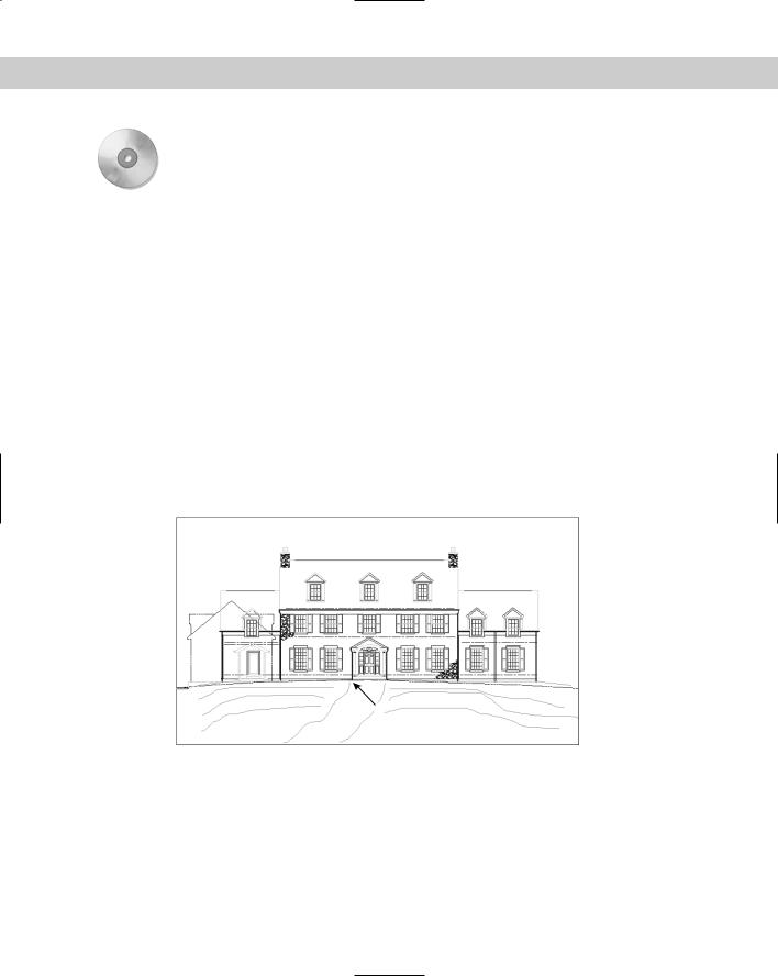
2.Save the file as ab16-08.dwg in your AutoCAD Bible folder. It shows the front elevation of a house. You’ll add the sketched path and contours, as shown in Figure 16-37.
3.Type skpoly . Set SKPOLY to 1 and press Enter.
4.Type sketch . At the Record increment <0'-0">: prompt, type 1 to set the record increment to 1".
5.At the Sketch. Pen eXit Quit Record Erase Connect. prompt, move the cursor to 1 in Figure 16-37. Click the pick button to put the pen down and draw the first line of the path. Click the pick button to put the pen up.
6.Use the same technique to draw the other lines in Figure 16-37. If you make a mistake, type q to quit and then start again.
7.After you’re done, type r to record the lines.
8.Type x to end the SKETCH command.
9.Save your drawing.
1
Figure 16-37: A sketched path and contours.
Digitizing Drawings with the TABLET Command
In Chapter 3, I explained that you can use a digitizer to execute commands. One important use for a digitizer is to copy paper drawings into your drawing. Many companies have used this technique to copy old drawings that were drafted by hand so that they could be edited electronically. Digitizing can also be used to copy artwork and logos into a drawing.
484 Part II Drawing in Two Dimensions
To digitize a paper drawing, you use a special digitizing mode that turns the entire digitizer into a drawing tablet. To start the TABLET command, choose Tools Tablet and choose one of the options.
If you’ve been using the digitizer to execute commands, you need to reconfigure it to eliminate the command areas and enlarge the drawing area. Use the Configure option of the TABLET command and reconfigure the digitizer for 0 tablet menus. Respecify the screen pointing area so that the fixed screen pointing area covers the entire digitizing area.
Attach the paper drawing securely to the digitizer so that it won’t move as you work.
To set up the digitizing mode, start the TABLET command and choose the Calibrate option. The option prompts you to pick two points on the paper drawing and specify which coordinates they represent. To do this you need to mark two points on the paper drawing; take out a ruler and measure their distance. If the drawing has a title block, two corners of the title block are distinctive points to mark and measure. If the drawing is drawn to a scale — and it probably is — the coordinates you type should be the distance in real life, not the measurement. In other words, if the two horizontal points are 1 inch apart and 1 inch represents 48 inches (a scale of 1=48), you could enter 0,0 for the first point and 48,0 for the second point. However, it is usually useful to choose points over a wider area of your drawing. You can calibrate more than two points if you want.
Note If your drawing is distorted or uses a perspective view that you want to straighten out, you can calibrate additional points and choose either Affine or Projective calibration to account for the distortion. Affine calibration requires at least three points and scales the X and Y axes separately. Projective calibration requires at least four points and stretches the coordinates to adjust for the perspective view. You can provide up to 31 calibration points.
After you finish specifying calibration points and coordinates, press Enter. Now your entire tablet can be used only for picking points. You can press F12 to use a menu or toolbar and press F12 again to return to picking points, or type commands on the command line.
Note You can turn Tablet mode on and off by starting the TABLET command and choosing the On and Off options. Tablet calibration settings are lost when you close the drawing session.
Choose the command that you need and pick points along the paper drawing. After you’re done, turn off Tablet mode and do any necessary editing and cleanup.
In this exercise, you practice digitizing drawings. If you have a digitizer, you can try this exercise. Otherwise, skip it.
STEPS: Digitizing Drawings
1.Start a new drawing using acad.dwt or aclt.dwt as your template.
2.Save the file as ab16-09.dwg in your AutoCAD Bible folder. This is a sheet metal template as shown in Figure 16-38.
3.Make a photocopy of Figure 16-38 and tape it to the active area of your digitizer.
4.Choose Tools Tablet Calibrate. Follow the prompts:
Digitize point #1: Pick 1 in Figure 16-38. Enter coordinates for point #1: 0,0
Digitize point #2: Pick 2 in Figure 16-38. Enter coordinates for point #2: 7,5 Digitize point #3 (or RETURN to end):