

- •Contents
- •Contents at a Glance
- •Acknowledgments
- •Preface
- •Is This Book for You?
- •How This Book Is Organized
- •How to Use This Book
- •Doing the Exercises
- •Conventions Used in This Book
- •What the Icons Mean
- •About the CD-ROM
- •Other Information
- •Contacting the Author
- •Foreword
- •Credits
- •About the Author
- •Summary
- •AutoCAD’s Advantages
- •Comparing AutoCAD and AutoCAD LT
- •Starting AutoCAD and AutoCAD LT
- •Creating a New Drawing
- •Using the AutoCAD and AutoCAD LT Interface
- •Creating a New Folder
- •Using the Interface
- •Saving a Drawing
- •Closing a Drawing and Exiting from AutoCAD and AutoCAD LT
- •Summary
- •Creating a New Drawing from a Template
- •Working with Templates
- •Opening a Drawing with Default Settings
- •Opening an Existing Drawing
- •Using an Existing Drawing as a Prototype
- •Saving a Drawing Under a New Name
- •Summary
- •The Command Line and Dynamic Input
- •Command Techniques
- •Of Mice and Pucks
- •Getting Help
- •Summary
- •Typing Coordinates
- •Displaying Coordinates
- •Picking Coordinates on the Screen
- •Overriding Coordinate Settings
- •Locating Points
- •Summary
- •Choosing Unit Types
- •Drawing Limits
- •Understanding Scales
- •Creating a Title Block
- •Specifying Common Setup Options
- •Customizing with the MVSETUP Command
- •Using the Setup Wizards
- •Summary
- •Using the LINE Command
- •Drawing Rectangles
- •Drawing Polygons
- •Creating Construction Lines
- •Creating Rays
- •Summary
- •Drawing Circles
- •Drawing Arcs
- •Creating Ellipses and Elliptical Arcs
- •Making Donuts
- •Placing Points
- •Summary
- •Panning
- •Using the ZOOM Command
- •Using Aerial View
- •Saving Named Views
- •Working with Tiled Viewports
- •Using Snap Rotation
- •Understanding User Coordinate Systems
- •Creating Isometric Drawings
- •Summary
- •Editing a Drawing
- •Selecting Objects
- •Summary
- •Copying and Moving Objects
- •Resizing Commands
- •Using Construction Commands
- •Creating a Revision Cloud
- •Hiding Objects with a Wipeout
- •Double-Clicking to Edit Objects
- •Grips
- •Editing with the Properties Palette
- •Selection Filters
- •Groups
- •Summary
- •Working with Layers
- •Changing Object Color, Linetype, and Lineweight
- •Working with Linetype Scales
- •Importing Layers and Linetypes from Other Drawings
- •Matching Properties
- •Summary
- •Drawing-Level Information
- •Object-Level Information
- •Measurement Commands
- •AutoCAD’s Calculator
- •Summary
- •Creating Single-Line Text
- •Understanding Text Styles
- •Creating Multiline Text
- •Creating Tables
- •Inserting Fields
- •Managing Text
- •Finding Text in Your Drawing
- •Checking Your Spelling
- •Customizing the spelling dictionary
- •Summary
- •Working with Dimensions
- •Drawing Linear Dimensions
- •Drawing Aligned Dimensions
- •Creating Baseline and Continued Dimensions
- •Dimensioning Arcs and Circles
- •Dimensioning Angles
- •Creating Ordinate Dimensions
- •Drawing Leaders
- •Using Quick Dimension
- •Editing Dimensions
- •Summary
- •Understanding Dimension Styles
- •Defining a New Dimension Style
- •Changing Dimension Styles
- •Creating Geometric Tolerances
- •Summary
- •Creating and Editing Polylines
- •Drawing and Editing Splines
- •Creating Regions
- •Creating Boundaries
- •Creating Hatches
- •Creating and Editing Multilines
- •Creating Dlines
- •Using the SKETCH Command
- •Digitizing Drawings with the TABLET Command
- •Summary
- •Preparing a Drawing for Plotting or Printing
- •Creating a Layout in Paper Space
- •Working with Plot Styles
- •Plotting a Drawing
- •Summary
- •Combining Objects into Blocks
- •Inserting Blocks and Files into Drawings
- •Managing Blocks
- •Creating and Using Dynamic Blocks
- •Using Windows Features
- •Working with Attributes
- •Summary
- •Understanding External References
- •Editing an Xref within Your Drawing
- •Controlling Xref Display
- •Managing Xrefs
- •Summary
- •Preparing for Database Connectivity
- •Connecting to Your Database
- •Linking Data to Drawing Objects
- •Creating Labels
- •Querying with the Query Editor
- •Working with Query Files
- •Summary
- •Working with 3D Coordinates
- •Using Elevation and Thickness
- •Working with the User Coordinate System
- •Summary
- •Working with the Standard Viewpoints
- •Using DDVPOINT
- •Working with the Tripod and Compass
- •Displaying a Quick Plan View
- •Shading Your Drawing
- •Using 3D Orbit
- •Using Tiled Viewports
- •Defining a Perspective View
- •Laying Out 3D Drawings
- •Summary
- •Drawing Surfaces with 3DFACE
- •Drawing Surfaces with PFACE
- •Creating Polygon Meshes with 3DMESH
- •Drawing Standard 3D Shapes
- •Drawing a Revolved Surface
- •Drawing an Extruded Surface
- •Drawing Ruled Surfaces
- •Drawing Edge Surfaces
- •Summary
- •Drawing Standard Shapes
- •Creating Extruded Solids
- •Drawing Revolved Solids
- •Creating Complex Solids
- •Sectioning and Slicing Solids
- •Using Editing Commands in 3D
- •Editing Solids
- •Listing Solid Properties
- •Summary
- •Understanding Rendering
- •Creating Lights
- •Creating Scenes
- •Working with Materials
- •Using Backgrounds
- •Doing the Final Render
- •Summary
- •Accessing Drawing Components with the DesignCenter
- •Accessing Drawing Content with Tool Palettes
- •Setting Standards for Drawings
- •Organizing Your Drawings
- •Working with Sheet Sets
- •Maintaining Security
- •Keeping Track of Referenced Files
- •Handling Errors and Crashes
- •Managing Drawings from Prior Releases
- •Summary
- •Importing and Exporting Other File Formats
- •Working with Raster Images
- •Pasting, Linking, and Embedding Objects
- •Summary
- •Sending Drawings
- •Opening Drawings from the Web
- •Creating Object Hyperlinks
- •Publishing Drawings
- •Summary
- •Working with Customizable Files
- •Creating Keyboard Shortcuts for Commands
- •Customizing Toolbars
- •Customizing Tool Palettes
- •Summary
- •Creating Macros with Script Files
- •Creating Slide Shows
- •Creating Slide Libraries
- •Summary
- •Creating Linetypes
- •Creating Hatch Patterns
- •Summary
- •Creating Shapes
- •Creating Fonts
- •Summary
- •Working with the Customization File
- •Customizing a Menu
- •Summary
- •Introducing Visual LISP
- •Getting Help in Visual LISP
- •Working with AutoLISP Expressions
- •Using AutoLISP on the Command Line
- •Creating AutoLISP Files
- •Summary
- •Creating Variables
- •Working with AutoCAD Commands
- •Working with Lists
- •Setting Conditions
- •Managing Drawing Objects
- •Getting Input from the User
- •Putting on the Finishing Touches
- •Summary
- •Understanding Local and Global Variables
- •Working with Visual LISP ActiveX Functions
- •Debugging Code
- •Summary
- •Starting to Work with VBA
- •Writing VBA Code
- •Getting User Input
- •Creating Dialog Boxes
- •Modifying Objects
- •Debugging and Trapping Errors
- •Moving to Advanced Programming
- •Summary
- •A Final Word
- •Installing AutoCAD and AutoCAD LT
- •Configuring and Using Workspaces
- •Configuring AutoCAD
- •Starting AutoCAD Your Way
- •Configuring a Plotter
- •Discovering AutoCAD and AutoCAD LT
- •Accessing Technical Support
- •Autodesk User Groups
- •Internet Resources
- •System Requirements
- •Using the CD-ROM with Microsoft Windows
- •What’s on the CD-ROM
- •Troubleshooting
- •Index
472 Part II Drawing in Two Dimensions
Using the SOLID command
The SOLID command creates solidly filled areas. (It is not directly related to 3D solids.) In general, BHATCH is much more flexible. However, although the SOLID command is a 2D command, it’s sometimes used in 3D drawing. When you create a 2D solid and give it thickness, it creates surfaces with tops and bottoms. See Chapter 24 for a description of how to use the SOLID command to create 3D models.
SOLID creates straight-edged shapes. If FILL is on, AutoCAD or AutoCAD LT fills in the shape with a solid fill (that’s why it’s called SOLID).
To draw a solid, type solid . The command prompts you for first, second, third, and fourth points. You must specify these points in zigzag order, not around the perimeter of the shape. After the fourth point, the command continues to prompt you for third and fourth points, which you can use to create new adjacent solids. Press Enter to end the command.
Creating and Editing Multilines
Multilines are sets of parallel lines that you draw with one command. You can specify how far apart they are, and each line can have its own color and linetype. Multilines are used for drawing architectural plans where you need to draw an inner and outer wall. To draw a multiline, you first define, save, and load a multiline style. Then you can use the multiline style to draw multilines. There is a separate command for editing multilines that enables you to break multiline intersections, as you would for the doors and windows in a floor plan. Figure 16-27 shows a floor plan for an apartment drawn using multilines.
AutoCAD LT doesn’t have the Multiline feature but has a similar feature called Dlines. I cover dlines in the next section, “Creating Dlines.”
Figure 16-27: A floor plan of an apartment that is drawn using multilines.
Thanks to Bill Wynn of New Windsor, Maryland, for this drawing.
Chapter 16 Drawing Complex Objects 473
Creating a multiline style
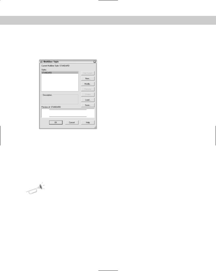
The first step in drawing multilines is to design the multiline style. To create a multiline style, choose Format Multiline Style to open the Multiline Style dialog box, as shown in Figure 16-28.
Figure 16-28: The Multiline Style dialog box.
Like text styles and dimension styles, multiline styles group a set of properties under one name. The default multiline style, called Standard, defines two lines 1 unit apart. Multiline styles have two parts: element properties and multiline properties. The element properties define each individual line element. The multiline properties define properties that apply to the multiline as a whole.
Defining multiline style properties
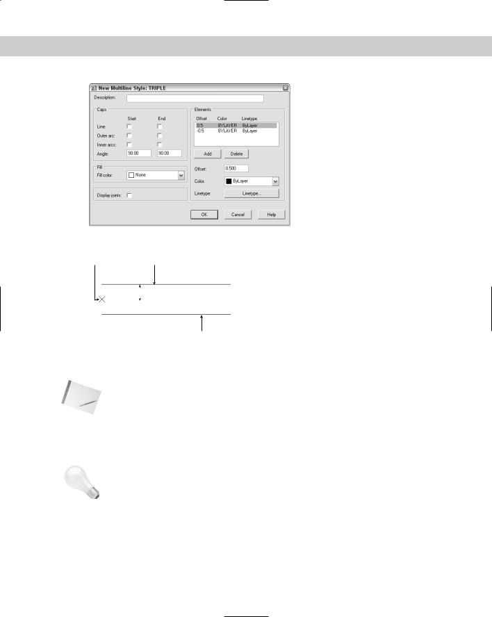
To start defining the multiline style, click New. In the Create New Multiline Style dialog box, type a name in the New Style Name text box and click Continue. The New Multiline Style dialog box opens, as shown in Figure 16-29.
New |
The Multiline Style dialog box has been updated; the New Multiline Style dialog box is now |
Feature |
a combination of the previous Element Properties and Multiline Properties dialog boxes. |
|
The Elements section lists the current elements of the multiline. Elements are simply the lines that make up the multiline. The offset defines the distance of the line from the start point when you start to draw. An offset of zero places the line on the start point. As you can see, the Standard multiline style has two elements, each 0.5 units from the start point. Figure 16-30 shows the Standard multiline style as it appears in relation to the start point that you pick.
474 Part II Drawing in Two Dimensions
Note
Tip
Figure 16-29: The New Multiline Style dialog box.
Start point First element

 .5 units
Second element
Figure 16-30: The Standard multiline style places two lines on either side of the start point.
You can change the relationship of the start point and the element lines by using the Justification option when you draw the multiline, as explained later in the “Drawing multilines” section.
To define the element lines of a multiline style, follow these steps:
1.In the Elements section, highlight the first element. Even if you typed a new name for the multiline style, the elements listed are the same as the current multiline style.
When creating a new multiline style, first set as current the multiline style that is the most similar to the one that you want to create.
2.In the Offset box, type the offset value that you want. The offset should be zero if you want the line to appear on your pick points, a positive number (in units) if you want the line to appear above your pick points, and a negative number (in units) if you want the line to appear below your pick points. (This assumes the default of zero justification, explained later in this chapter.)
Chapter 16 Drawing Complex Objects 475
Tip
Note
When defining the multiline style elements, think of the multiline as being drawn horizontally to the right to help you visualize what above and below mean.
3.Choose Color to choose a color for the line element.
4.Choose Linetype to choose a linetype for the line element.
5.Choose Add to add a new element or Delete to delete a listed element.
6.To define the next element, select the second element in the Elements box and repeat Steps 2 through 4. Continue to define elements until you’re done.
7.If you want, enter a description for the multiline style in the Description text box.
8.Click OK to return to the Multiline Style dialog box.
A multiline style can have up to 16 elements. All 16 elements must be on the same layer, but you can vary the linetypes and colors.
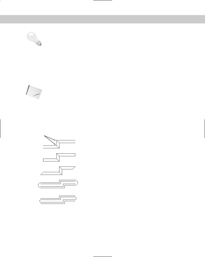
Use the left side of the New Multiline Style dialog box to set the overall properties of the multiline. Caps cross the ends of multilines to close them. You can choose line or arc caps. Figure 16-31 shows the effects of all of the possible choices in this box. You can also turn Fill on or off and choose a color to add a solid fill to the multiline. To display a line at the junction of each line segment, check the Display Joints check box. After you make your choices, click OK to return to the Multiline Style dialog box.
Display joints
 Line-90o
 Line-45o
 Outer arc
 Inner arc
Figure 16-31: The results of choosing the various options in the New Multiline Style dialog box.
Saving a new multiline style
Before you can use the multiline style, you must save it. AutoCAD saves multiline styles in a file with the .mln file name extension. After you click Save, the Save Multiline Style dialog box opens.
476 Part II Drawing in Two Dimensions
In general, you can save your multiline styles in the default file, which is acad.mln. Click Save to return to the Multiline Style dialog box.
Loading a multiline style
Like linetypes, multiline styles must be loaded before you can use them. Choose Load to open the Load Multiline Styles dialog box. Choose the style that you created from the list and click OK.
You return to the Multiline Styles dialog box. You’re now ready to use the multiline style. Click OK to return to your drawing.
You can also use the Multiline Style dialog box to rename multiline styles and make another multiline style current.
On the |
The drawing used in the following exercise on creating a multiline style, ab16-g.dwg, is in |
CD-ROM |
the Drawings folder on the CD-ROM. |
STEPS: Creating a Multiline Style
1.Open ab16-g.dwg from your CD-ROM.
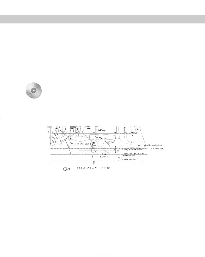
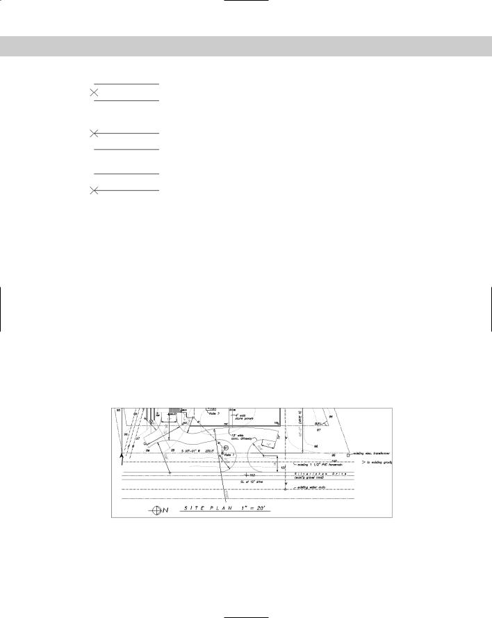
2.Save the file as ab16-07.dwg in your AutoCAD Bible folder. This is a site plan, shown in Figure 16-32.
Figure 16-32: The parallel lines at the bottom of the site plan can be drawn by using a multiline.
3.Choose Format Multiline Style to open the Multiline Style dialog box. Click New. In the text box, type siteplan. Choose Continue.
4.In the Elements section of the dialog box, the top element should be highlighted. Change the offset to 0, the color to black (it may list as white), and the linetype to DASHDOT.
5.Highlight the second element. Change the offset to –132 (11' × 12"), the color to magenta, and the linetype to continuous.
6.Click Add. Change the offset to –180 (15' × 12"), the color to red, and the linetype to center.
7.Click Add. Change the offset to –228 (19' × 12"), the color to magenta, and the linetype to continuous.

Chapter 16 Drawing Complex Objects 477
8.Click Add. Change the offset to –360 (30' × 12"), the color to black, and the linetype to dashdot.
9.Click Add. Change the offset to –480 (40' × 12"), the color to red, and the linetype to center.
10.Click OK. In the Multiline Style dialog box, click Save.
Caution |
If you are using someone else’s computer, check with the owner before saving the linestyle |
|
to acad.mln. You can’t do any damage, but the owner may not want to have your multiline |
|
style there. You can change the name in the File Name text box to something else, such as |
|
my_mls.mln. |
11.In the Save Multiline Style dialog box, you should see acad.mln in the File Name text box. You can also type a new MLN file name. Choose Save.
12.Choose Load in the Multiline Style dialog box. In the Load Multiline Styles dialog box, highlight the SITEPLAN multiline style, and choose OK. With the new multiline style selected, choose Set Current, and click OK again to return to your drawing.
13.Save your drawing. If you’re continuing on to the next exercise, keep the drawing open.
Drawing multilines
Defining a multiline style is the hard part. As soon as the style is defined, saved, loaded, and made current, you can draw with it. You may find that you need some practice to get the hang of it because you’re drawing more than one line at once. To draw a multiline, choose Draw Multiline to start the MLINE command. The command responds with the Specify start point or [Justification/Scale/STyle]: prompt. The prompt also displays the current justification, scale, and style. The default is to pick a point. From there you get the Specify next point: prompt. After the first segment, you get the Specify next point or [Undo]: prompt, and after the second segment, the Specify next point or [Close/Undo]: prompt. Here is how to use the options:
Justification: You can choose Zero, Top, or Bottom.
•Zero places the element that has a zero offset in the multiline definition at the pick point. You do not need to have a line at zero offset, as is the case with the Standard multiline style. The top example in Figure 16-33 shows the Standard multiline style with zero justification.
•Top places the line with the highest positive offset at the pick point. The middle example in Figure 16-33 shows the Standard multiline style with top justification.
•Bottom places the line with the highest negative offset at the pick point. The bottom example in Figure 16-33 shows the Standard multiline style with bottom justification.
Scale: Multiplies the offset values in the multiline definition by the scale. The Standard multiline style places two lines 1 unit apart. A scale of 6 would place them 6 units apart.
Style: Enables you to specify the current multiline style. Type ? to get a list of the available multiline styles.
478 Part II Drawing in Two Dimensions
Figure 16-33: Drawing a multiline using the Standard multiline style in zero, top, and bottom justification.
As you draw a multiline, whenever you create a corner by changing direction, the command creates a clean corner.
STEPS: Drawing Multilines
1.Continue from the previous exercise. (If you didn’t do the previous exercise, you should do it to create the multiline style.) Set a running object snap for intersection.
2.Choose Draw Multiline. The prompt displays the following message:
Justification = Top, Scale = 1.00, Style = SITEPLAN
3.At the Specify start point or [Justification/Scale/STyle]: prompt, choose the From object snap. At the Base point: prompt, choose 1 in Figure 16-35. (If necessary,
press Tab until you get the Intersection object snap.) At the <Offset>: prompt, type
@0,–10' .
4.At the Specify next point: prompt, move the cursor to the right and type 255' . If you want, you can experiment by drawing other line segments. Press Enter to end the command. The drawing should look like Figure 16-34.
5.Save your drawing.
1
Figure 16-34: The completed multiline.
Chapter 16 Drawing Complex Objects 479
Editing multilines
No matter how many segments it contains, the entire multiline is one object. Many editing commands simply do not work with multilines. Table 16-1 shows the editing commands and whether they work with multilines.
Table 16-1: Using Editing Commands with Multilines
Command |
Usable with Multilines |
Command |
Usable with Multilines |
|
|
|
|
ARRAY |
yes |
LENGTHEN |
no |
BREAK |
no |
MIRROR |
yes |
CHAMFER |
no |
MOVE |
yes |
COPY |
yes |
ROTATE |
yes |
EXPLODE |
yes |
SCALE |
yes |
EXTEND |
yes |
STRETCH |
yes |
FILLET |
no |
TRIM |
yes |
|
|
|
|
New |
The capability to trim and extend multilines is new for AutoCAD 2006. |
Feature |
|
You can use grips to stretch, move, copy, mirror, and rotate multilines.
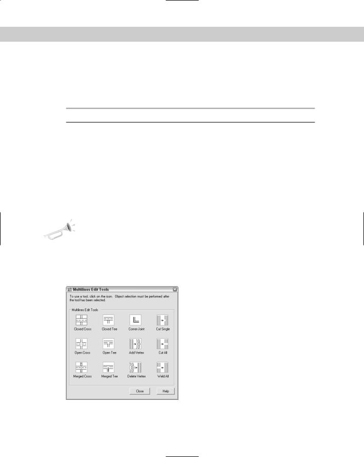
To edit multilines, you use the MLEDIT command. To start MLEDIT, double-click the multiline (or choose Modify Object Multiline) to open the Multilines Edit Tools dialog box, shown in Figure 16-35.
Figure 16-35: The Multilines Edit Tools dialog box.