

- •Contents
- •Contents at a Glance
- •Acknowledgments
- •Preface
- •Is This Book for You?
- •How This Book Is Organized
- •How to Use This Book
- •Doing the Exercises
- •Conventions Used in This Book
- •What the Icons Mean
- •About the CD-ROM
- •Other Information
- •Contacting the Author
- •Foreword
- •Credits
- •About the Author
- •Summary
- •AutoCAD’s Advantages
- •Comparing AutoCAD and AutoCAD LT
- •Starting AutoCAD and AutoCAD LT
- •Creating a New Drawing
- •Using the AutoCAD and AutoCAD LT Interface
- •Creating a New Folder
- •Using the Interface
- •Saving a Drawing
- •Closing a Drawing and Exiting from AutoCAD and AutoCAD LT
- •Summary
- •Creating a New Drawing from a Template
- •Working with Templates
- •Opening a Drawing with Default Settings
- •Opening an Existing Drawing
- •Using an Existing Drawing as a Prototype
- •Saving a Drawing Under a New Name
- •Summary
- •The Command Line and Dynamic Input
- •Command Techniques
- •Of Mice and Pucks
- •Getting Help
- •Summary
- •Typing Coordinates
- •Displaying Coordinates
- •Picking Coordinates on the Screen
- •Overriding Coordinate Settings
- •Locating Points
- •Summary
- •Choosing Unit Types
- •Drawing Limits
- •Understanding Scales
- •Creating a Title Block
- •Specifying Common Setup Options
- •Customizing with the MVSETUP Command
- •Using the Setup Wizards
- •Summary
- •Using the LINE Command
- •Drawing Rectangles
- •Drawing Polygons
- •Creating Construction Lines
- •Creating Rays
- •Summary
- •Drawing Circles
- •Drawing Arcs
- •Creating Ellipses and Elliptical Arcs
- •Making Donuts
- •Placing Points
- •Summary
- •Panning
- •Using the ZOOM Command
- •Using Aerial View
- •Saving Named Views
- •Working with Tiled Viewports
- •Using Snap Rotation
- •Understanding User Coordinate Systems
- •Creating Isometric Drawings
- •Summary
- •Editing a Drawing
- •Selecting Objects
- •Summary
- •Copying and Moving Objects
- •Resizing Commands
- •Using Construction Commands
- •Creating a Revision Cloud
- •Hiding Objects with a Wipeout
- •Double-Clicking to Edit Objects
- •Grips
- •Editing with the Properties Palette
- •Selection Filters
- •Groups
- •Summary
- •Working with Layers
- •Changing Object Color, Linetype, and Lineweight
- •Working with Linetype Scales
- •Importing Layers and Linetypes from Other Drawings
- •Matching Properties
- •Summary
- •Drawing-Level Information
- •Object-Level Information
- •Measurement Commands
- •AutoCAD’s Calculator
- •Summary
- •Creating Single-Line Text
- •Understanding Text Styles
- •Creating Multiline Text
- •Creating Tables
- •Inserting Fields
- •Managing Text
- •Finding Text in Your Drawing
- •Checking Your Spelling
- •Customizing the spelling dictionary
- •Summary
- •Working with Dimensions
- •Drawing Linear Dimensions
- •Drawing Aligned Dimensions
- •Creating Baseline and Continued Dimensions
- •Dimensioning Arcs and Circles
- •Dimensioning Angles
- •Creating Ordinate Dimensions
- •Drawing Leaders
- •Using Quick Dimension
- •Editing Dimensions
- •Summary
- •Understanding Dimension Styles
- •Defining a New Dimension Style
- •Changing Dimension Styles
- •Creating Geometric Tolerances
- •Summary
- •Creating and Editing Polylines
- •Drawing and Editing Splines
- •Creating Regions
- •Creating Boundaries
- •Creating Hatches
- •Creating and Editing Multilines
- •Creating Dlines
- •Using the SKETCH Command
- •Digitizing Drawings with the TABLET Command
- •Summary
- •Preparing a Drawing for Plotting or Printing
- •Creating a Layout in Paper Space
- •Working with Plot Styles
- •Plotting a Drawing
- •Summary
- •Combining Objects into Blocks
- •Inserting Blocks and Files into Drawings
- •Managing Blocks
- •Creating and Using Dynamic Blocks
- •Using Windows Features
- •Working with Attributes
- •Summary
- •Understanding External References
- •Editing an Xref within Your Drawing
- •Controlling Xref Display
- •Managing Xrefs
- •Summary
- •Preparing for Database Connectivity
- •Connecting to Your Database
- •Linking Data to Drawing Objects
- •Creating Labels
- •Querying with the Query Editor
- •Working with Query Files
- •Summary
- •Working with 3D Coordinates
- •Using Elevation and Thickness
- •Working with the User Coordinate System
- •Summary
- •Working with the Standard Viewpoints
- •Using DDVPOINT
- •Working with the Tripod and Compass
- •Displaying a Quick Plan View
- •Shading Your Drawing
- •Using 3D Orbit
- •Using Tiled Viewports
- •Defining a Perspective View
- •Laying Out 3D Drawings
- •Summary
- •Drawing Surfaces with 3DFACE
- •Drawing Surfaces with PFACE
- •Creating Polygon Meshes with 3DMESH
- •Drawing Standard 3D Shapes
- •Drawing a Revolved Surface
- •Drawing an Extruded Surface
- •Drawing Ruled Surfaces
- •Drawing Edge Surfaces
- •Summary
- •Drawing Standard Shapes
- •Creating Extruded Solids
- •Drawing Revolved Solids
- •Creating Complex Solids
- •Sectioning and Slicing Solids
- •Using Editing Commands in 3D
- •Editing Solids
- •Listing Solid Properties
- •Summary
- •Understanding Rendering
- •Creating Lights
- •Creating Scenes
- •Working with Materials
- •Using Backgrounds
- •Doing the Final Render
- •Summary
- •Accessing Drawing Components with the DesignCenter
- •Accessing Drawing Content with Tool Palettes
- •Setting Standards for Drawings
- •Organizing Your Drawings
- •Working with Sheet Sets
- •Maintaining Security
- •Keeping Track of Referenced Files
- •Handling Errors and Crashes
- •Managing Drawings from Prior Releases
- •Summary
- •Importing and Exporting Other File Formats
- •Working with Raster Images
- •Pasting, Linking, and Embedding Objects
- •Summary
- •Sending Drawings
- •Opening Drawings from the Web
- •Creating Object Hyperlinks
- •Publishing Drawings
- •Summary
- •Working with Customizable Files
- •Creating Keyboard Shortcuts for Commands
- •Customizing Toolbars
- •Customizing Tool Palettes
- •Summary
- •Creating Macros with Script Files
- •Creating Slide Shows
- •Creating Slide Libraries
- •Summary
- •Creating Linetypes
- •Creating Hatch Patterns
- •Summary
- •Creating Shapes
- •Creating Fonts
- •Summary
- •Working with the Customization File
- •Customizing a Menu
- •Summary
- •Introducing Visual LISP
- •Getting Help in Visual LISP
- •Working with AutoLISP Expressions
- •Using AutoLISP on the Command Line
- •Creating AutoLISP Files
- •Summary
- •Creating Variables
- •Working with AutoCAD Commands
- •Working with Lists
- •Setting Conditions
- •Managing Drawing Objects
- •Getting Input from the User
- •Putting on the Finishing Touches
- •Summary
- •Understanding Local and Global Variables
- •Working with Visual LISP ActiveX Functions
- •Debugging Code
- •Summary
- •Starting to Work with VBA
- •Writing VBA Code
- •Getting User Input
- •Creating Dialog Boxes
- •Modifying Objects
- •Debugging and Trapping Errors
- •Moving to Advanced Programming
- •Summary
- •A Final Word
- •Installing AutoCAD and AutoCAD LT
- •Configuring and Using Workspaces
- •Configuring AutoCAD
- •Starting AutoCAD Your Way
- •Configuring a Plotter
- •Discovering AutoCAD and AutoCAD LT
- •Accessing Technical Support
- •Autodesk User Groups
- •Internet Resources
- •System Requirements
- •Using the CD-ROM with Microsoft Windows
- •What’s on the CD-ROM
- •Troubleshooting
- •Index
Chapter 16 Drawing Complex Objects 459
7.To see the new region, start the MOVE command. At the Select objects: prompt, pick 2. Move the region to the right; the exact distance is not important. You see both the new region and the original objects.
8.Save your drawing.
Creating Hatches
Hatches are patterns that fill in an area. Most types of drafting make use of hatching. In architectural drafting, hatched areas are used to indicate materials, such as insulation or grass. In mechanical drafting, hatching often indicates hidden areas or certain materials. AutoCAD and AutoCAD LT provide a large number of hatch patterns. Hatches are created from repeating patterns of lines. You can also create solid fills in the same way that you create hatch patterns.
Cross- |
Chapter 31 explains how to create your own hatch patterns. |
Reference |
|
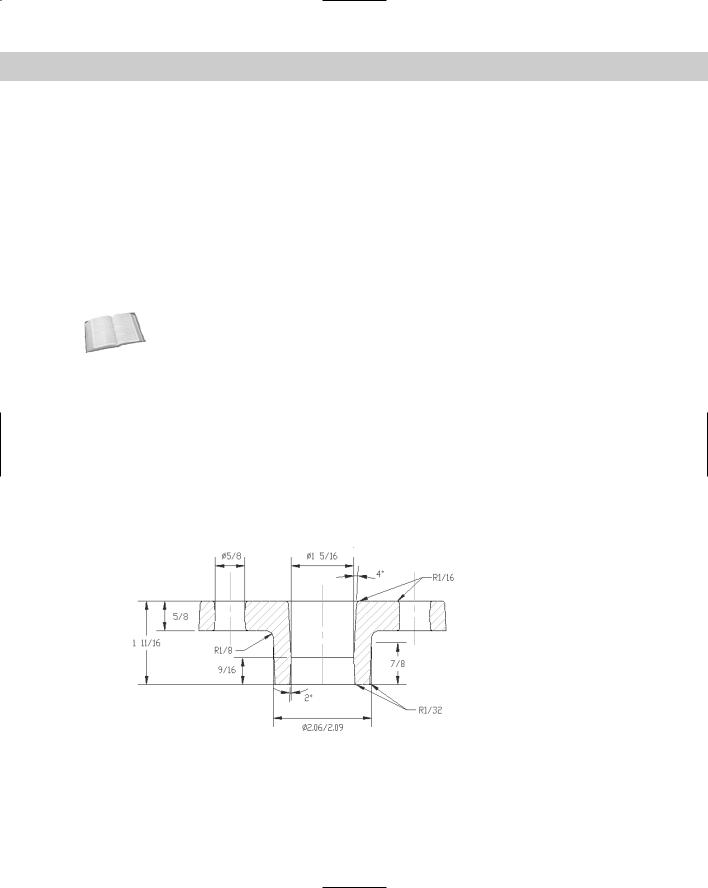
Figure 16-16 shows a drawing with a simple hatch pattern. Here the cross-section shows solid metal that is hatched to distinguish it from the holes.
Understanding hatch patterns
Hatch patterns may seem complex, but they are easy to use, after you understand how they work. Hatch patterns have two qualities that are similar to dimensions:
They are blocks. This means that all of the lines that fill in an area are one object. Blocks are covered in Chapter 18.
They are associative. If you edit the object that is hatched, the hatch automatically adjusts to fit the new shape of the object.
Figure 16-16: Hatch patterns help you to distinguish different materials or textures.
Thanks to Jerry Bottenfield of Clow Valve Company, Oskaloosa, Iowa, for this drawing.
460 Part II Drawing in Two Dimensions
|
You have several ways to specify exactly which area you want to hatch. Often, the key to suc- |
|
cessful hatching lies in how you construct the area that you want to hatch. For example, you |
|
can use the BOUNDARY and REGION commands covered in previous sections of this chapter |
|
to create complex closed areas that you can hatch. |
|
AutoCAD stores hatch pattern definitions in the acad.pat and acadiso.pat files. AutoCAD |
|
LT uses the aclt.pat and acltiso.pat files. If you create your own hatch patterns, you can |
|
put them in another file with the .pat file name extension. |
Tip |
Create a separate layer for hatch patterns. You may want to turn off or freeze your hatch layer |
|
to reduce visual clutter or assist in selecting objects. Hatches are also typically a different |
|
color than the model that you’re hatching. |
Defining a hatch
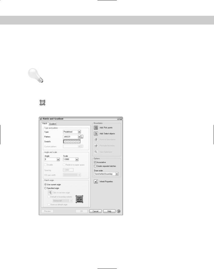
To hatch an area, choose Hatch from the Draw toolbar. This starts the BHATCH command. The Hatch and Gradient dialog box opens with the Hatch tab on top, as shown in
Figure 16-17. (The AutoCAD LT dialog box doesn’t have a Gradient tab.)
Figure 16-17: The Hatch and Gradient dialog box with the Hatch tab on top.
Specifying the hatch type and pattern
Use the Hatch and Gradient dialog box to define your hatch. From the Type drop-down list, choose one of the three options:
Predefined: Enables you to select any of the standard hatch patterns.
Chapter 16 Drawing Complex Objects 461
User-defined: Enables you to define your own hatch pattern by specifying the angle and spacing, using the current linetype.
Custom: Enables you to choose a pattern that you’ve created in your own .pat file.
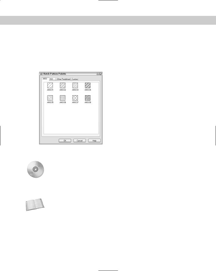
Click the Pattern drop-down list to choose the hatch patterns, or click the box marked with an ellipsis to open the Hatch Pattern palette and choose from the image tiles, as shown in Figure 16-18.
Figure 16-18: The Hatch Pattern palette, shown with the ANSI tab on top.
On the |
Mhatch is a program that creates solid fills for a selection of closed objects. Look in |
CD-ROM |
\Software\Ch16\mhatch. It works with AutoCAD only. |
In the palette, click the tabs to see the different types of hatches. Click the image tile to choose a hatch pattern and click OK. The palette is simply another method of choosing the hatch pattern — you can also choose the pattern by using the Pattern drop-down list. The swatch shows you how your chosen hatch will look.
Cross- |
You can drag hatches from your drawing to the Tools palette to create hatch tools that you |
Reference |
can then drag into your drawing. See Chapter 26 for a description of the Tools palette. |
|
The Custom Pattern drop-down list is available only if you have chosen Custom as the pattern type. Here you choose the name of your custom hatch pattern. I explain how to create custom hatch patterns in Chapter 31.
Setting the hatch angle and scale
Use the Angle text box to rotate the angle of the hatch pattern. You can choose from the dropdown list or type an angle. Watch out here, as many of the patterns are already defined at an angle. The hatch pattern in Figure 16-19 uses a 0-degree angle because ANSI31 is defined as diagonal lines.
462 Part II Drawing in Two Dimensions
The Scale box determines the scale of the hatch pattern. You can choose from the drop-down list or type a scale. A scale of 1 (the default) creates the hatch as defined. A scale of 0.5 shrinks it by one-half. Figure 16-19 shows two hatch patterns using the ANSI31 pattern. The left one uses a scale of 1, and the right one uses a scale of 0.5.
Scale = 1 |
Scale = .5 |
Figure 16-19: You can scale the hatch pattern to suit your needs.
The Spacing box and the Double check box are available if you choose a user-defined hatch pattern. A user-defined hatch uses the current linetype and creates a hatch based on the spacing and angle that you specify. Figure 16-20 shows a user-defined double hatch with an angle of 45 degrees and 0.1-unit spacing.
Figure 16-20: A user-defined hatch.
To define a user-defined hatch pattern:
1.Choose Hatch from the Draw toolbar to open the Hatch and Gradient dialog box.
2.In the Type drop-down list, choose User Defined.
Chapter 16 Drawing Complex Objects 463
3.In the Angle box, type an angle or choose one from the drop-down list. When creating a user-defined hatch, you need to specify the actual angle that you want to see.
4.In the Spacing box, enter the spacing between the lines. For example, type .5 to create a hatch pattern with lines 0.5 units apart.
5.If you want to cross-hatch so that the parallel lines are crossed by an equal number of perpendicular lines, check Double.
The ISO Pen Width box is available only for ISO predefined hatch patterns. This feature adjusts the scale of the pattern according to the pen width that you specify. When you choose a pen width from the drop-down list, the scale shown in the Scale box automatically changes to equal the pen width. Note that you still have to separately set the width of your plotter pens when you plot your drawing.
The Express Tools SUPERHATCH command creates a hatch pattern from an image, block, xref, or wipeout. Choose Express Draw Super Hatch. For information on installing Express Tools, see Appendix A.
Setting the hatch origin
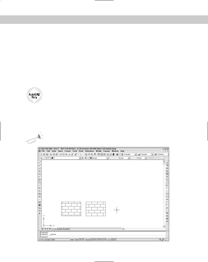
The Hatch Origin section lets you determine where the hatch pattern starts. By default, the pattern starts at the origin of the drawing, which is generally 0,0. As a result, the hatch in your object may start somewhere in the middle. This effect is very visible with certain hatch patterns, such as bricks. In Figure 16-21, you see two rectangles. The one on the left uses the default origin; the one on the right uses the lower-left corner of the rectangle as the origin.
New |
The ability to specify the hatch origin is new for AutoCAD 2006 and AutoCAD LT 2006. |
Feature |
|
Figure 16-21: You can specify where the hatch pattern starts.
464 Part II Drawing in Two Dimensions
To specify the hatch origin, choose the Specified Origin option. You can then click the Click to Set New Origin button to specify any point in your drawing. However, if you want the origin to be one of the corners or the center of the hatched boundary area, check the Default to Boundary Extents check box and choose one of the options from the drop-down list.
If you always want to use the same hatch origin (such as the lower-left corner of the boundary), check the Store as Default Origin check box.
Determining the hatch boundary
New
Feature
Hatching an entire object is the simplest way to place a hatch. However, the area that you want to hatch is often fairly complex, and the program needs to do some calculations to determine the area.
The Hatch and Gradient dialog box offers two ways to specify the hatch boundary: you can pick points inside an area and let the command try to find an enclosed boundary, or you can select objects. If you want to hatch an entire object, follow these steps:
1.Choose Add: Select Objects. You return temporarily to your drawing.
2.Select all of the objects that you want to hatch. You can use all of the standard objectselection options to select objects. Remove and Add are especially helpful.
3.Press Enter to end object selection and return to the dialog box.
If the area you want to hatch does not neatly fit into one or more objects, choose Add: Pick Points. You return to your drawing and see the following:
Select internal point: Selecting everything...
Selecting everything visible...
Analyzing the selected data...
Select internal point:
The command is determining the boundary set, which is simply everything visible on the screen. At the Pick internal point or [Select objects/remove Boundaries]: prompt, pick a point that is inside the boundary that you want to hatch. You can continue to pick internal points to hatch adjoining areas. Each boundary is helpfully highlighted. Press Enter to return to the dialog box.
Two new features help you to create hatches more flexibly. You can remove and add boundaries as you define your hatch boundary. You can also hatch outside the display on the screen. The hatch pattern will extend to include the entire object or boundary that you specified.
Sometimes, you need more control over the boundary and also need to remove a boundary that you’ve selected, without starting from scratch. To remove a boundary, click the Remove Boundaries button in the dialog box. In your drawing, when you see the Select objects or [Add boundaries]: prompt, select the objects that you want to remove. For example, if you have an inner island that you want to hatch, then by default, the hatch excludes the island. One way to hatch the island is to remove its boundary.
If you choose the Add Boundaries option, you can either select additional objects or pick internal points. Press Enter when you’re done to return to the dialog box.
While you’re in your drawing, either before or after picking points or selecting objects, you can right-click to open a very useful shortcut menu. This shortcut menu enables you to manage the hatch boundary without returning to the dialog box. Choose from the following options
on the shortcut menu:

Chapter 16 Drawing Complex Objects 465
Enter: Returns you to the dialog box
Undo Last Select/Pick/Draw: Undoes your most recent object selection, point pick, or boundary change
Clear All: Undoes all of your picks/object selections
Pick Internal Point: Switches to picking internal points
Select Objects: Switches to selection of objects
Remove Boundaries: Lets you choose boundaries to remove
Hatch Origin: Lets you choose the hatch origin
Normal Island Detection: Sets island detection to Normal mode
Outer Island Detection: Sets island detection to Outer mode
Ignore Island Detection: Sets island detection to Ignore mode
Preview: Previews the hatch
Previewing the hatch before applying it is always a good idea. After previewing a hatch, rightclick to accept the preview and place the hatch. Press Esc or left-click to return to the Hatch and Gradient dialog box. From the dialog box, click OK to create the hatch and return to your drawing.
Note |
To display hatches, either solid fill or lines, the FILL system variable must be on, which it is by |
|
default. To turn FILL off, type fill and off . You must regenerate the drawing to see the |
|
effect. |
The dialog box has several other options:
Click Preview if you want to try it before you apply it.
Click View Selections if you want to temporarily return to your drawing and check which objects you’ve selected.
Uncheck Associative if you want to create a hatch that is not associated with its object. By default, hatches are associative.
Choose a draw order for hatches from the Draw Order drop-down list. By default, hatches display behind their boundaries, so that when you pick a boundary, you select the boundary, not the hatch.
Choose Inherit Properties to use the hatch type, pattern, angle, scale, and/or spacing of an existing hatch. You return to your drawing to pick a hatch pattern. You then return to the Hatch and Gradient dialog box.
Caution |
If you use the gap tolerance feature (which I cover in the “Other advanced options” section |
|
later in this chapter, subsequent hatches are set to nonassociative. If you want associative |
|
hatches for closed areas, be sure to choose Associative in the Composition area of the dialog |
|
box. |
Choose the Create Separate Hatches option to create separate hatch objects when you are hatching several separate closed areas. Otherwise, you create one hatch object that hatches these separated areas.
466 Part II Drawing in Two Dimensions
Islands
Islands are enclosed areas entirely inside a hatch boundary. Islands make hatching more difficult because you may or may not want to hatch the inside of the island.
Note Text is counted as an island, enabling you to hatch areas that contain text without hatching over the words.
Managing islands when you select objects to hatch
When you choose the hatching boundary by selecting objects, you must also select the islands. If you select the entire area by window, you automatically include the internal islands. If you need to pick individual objects, you must also pick the islands individually. If you later erase an island, you don’t lose hatch associativity, and the hatch regenerates so that it covers the entire outer boundary.
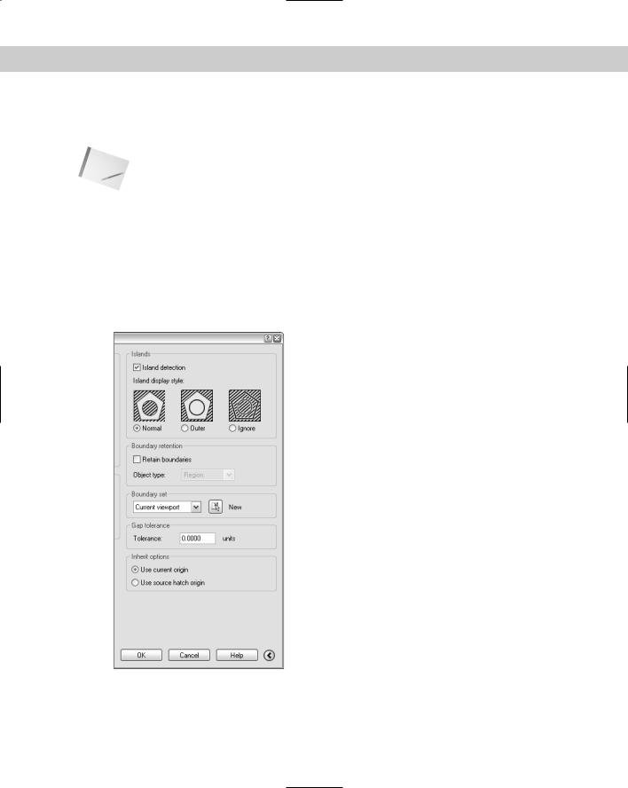
The resulting hatch depends on the boundary style. To specify the boundary style, in the Hatch and Gradient dialog box, click the right arrow at the lower-right corner of the dialog box to display the expanded section, shown in Figure 16-22.
Figure 16-22: The expanded section of the Hatch and Gradient dialog box offers advanced options to refine the hatching process.
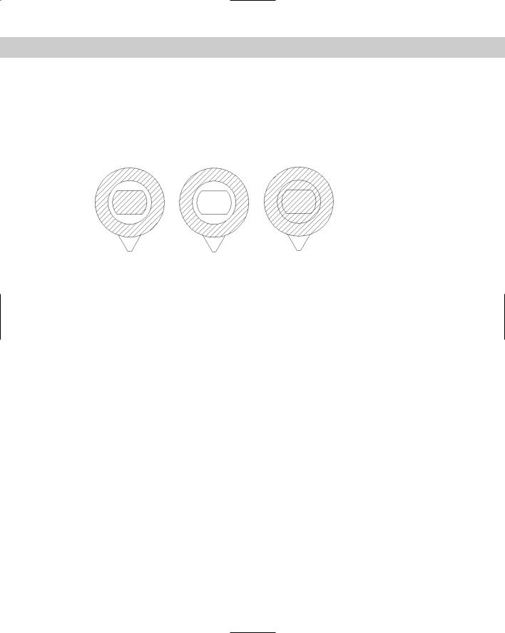
Three boundary styles affect how islands are hatched:
Normal: Hatches alternating areas so that the outer area is hatched, the next inner island is not hatched, the next inner island is hatched, and so on.
Chapter 16 Drawing Complex Objects 467
Outer: Hatches only the outer area and does not hatch any inner islands.
Ignore: Ignores islands and hatches everything from the outside in.
Figure 16-23 shows three copies of a nut hatched in the three styles. To hatch this model, I selected the entire model, except for the spout at the bottom, with a window.
Normal |
Outer |
Ignore |
Figure 16-23: Hatching islands using the three boundary styles.
Managing islands when you pick points to specify the hatch
When you pick points instead of selecting objects, you don’t need to select the islands. Hatching detects islands by default. As soon as you pick points, the Remove Islands button becomes available, and you can select the islands to remove them from consideration if you want to hatch them. For example, if you remove all of the islands shown in Figure 16-23, the result is the same as using the Ignore style, where everything inside the outside boundary is hatched.
Other advanced options
When you pick points to determine the hatch boundary, the hatching process uses the same mechanism as the BOUNDARY command to temporarily create a boundary for hatching. Check Retain Boundaries in the Boundary Retention section of the expanded dialog box if you want to draw the boundary as an object, and specify whether you want it to be a region or a polyline. Otherwise, the boundary is discarded when the hatch is placed. For more information, see the discussion of the BOUNDARY command earlier in this chapter.
You can also specify a smaller boundary set than the objects that are visible on-screen. Use this when you’re picking points and have such a complex drawing that the process of analyzing the visible objects takes a long time. To create a new boundary set, click the New button and specify a window in your drawing.
You can hatch areas that are not completely closed using the Gap Tolerance feature. In the Gap Tolerance text box, enter a value greater than the size of the gap. You can use values from 0 to 5000. In order to hatch an unclosed area in this way, you need to pick points rather than choose objects. When you do so, the Open Boundary Warning message opens. Click Yes to hatch the open boundary. Note that the hatch is not associative, which means that if you modify your almost closed area, you need to rehatch. Using this feature sets subsequent hatches as non-associative, so be sure to recheck the Associative check box in the main part of the dialog box.
You can fine-tune how a hatch inherits properties, specifically the hatch’s origin. Choose to use the current origin setting (from the left side of the dialog box) or use the setting of the source hatch.
468 Part II Drawing in Two Dimensions
Dragging and dropping hatch patterns
After you have spent the time creating a hatch, you may want to use that hatch in other drawings. You can open a .pat (hatch pattern) file from the DesignCenter, preview its hatch patterns, and drag any hatch pattern into any closed object in your current drawing. Here’s how to drag a hatch pattern from the DesignCenter:
1.Click DesignCenter on the Standard toolbar (or press Ctrl+2) to open the DesignCenter.
2.Use the Tree view to navigate to the folder that contains your acad.pat, aclt.pat, or other .pat file. If necessary, click the Desktop button and navigate from there.
Note |
To find the location of your .pat files, choose Tools Options and click the File tab. Double- |
|
click the Support File Search Path option. One of the paths listed contains your hatch files. |
3.Double-click the folder and select a hatch pattern (.pat) file. A preview of all of the hatch patterns appears in the right pane.
4.From the right pane of the DesignCenter, drag the hatch pattern that you want onto a closed object in your drawing (or an unclosed object with the gap tolerance value greater than the gap). If you need more options, right-click the pattern as you drag, then choose BHATCH from the shortcut menu to open the Hatch and Gradient dialog box, and then specify the hatch parameters in the usual way.
You can drag a hatch pattern to a tool palette to create a hatch with the properties — such as layer and angle — of the hatch in your drawing. Then you can drag that hatch tool onto any closed area in your drawing. The hatch automatically fills the area with the same properties. For more information on tool palettes, see Chapter 26.
Creating gradient fills
Gradients are fills that gradually change from dark to light or from one color to another. Use gradients to create presentation-quality illustrations without rendering. You can use gradients as a substitute for shading because they offer more-flexible options. AutoCAD LT doesn’t offer the gradient feature.
To create a gradient:
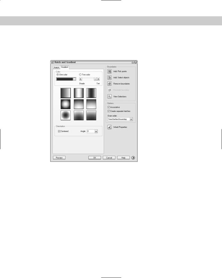
1.Choose Gradient from the Draw toolbar to open the Hatch and Gradient dialog box with the Gradient tab on top, shown in Figure 16-24.
2.Choose One Color or Two Color.
•If you choose One Color, click the ellipsis button to the right of the color swatch to open the Select Color dialog box, where you can choose the color you want. (For instructions on using this dialog box, see Chapter 11.) Then use the Shade/Tint slider to choose whether you want the gradient to range lighter or darker. You see the result in the gradient swatches below the slider.
•If you choose Two Color, you see two color swatches. Click each ellipsis button and choose a color.
3.Choose one of the nine gradient styles.
Chapter 16 Drawing Complex Objects 469
4.If you want the gradient to be symmetrical, check the Centered check box. To create a gradient that isn’t symmetrical, uncheck the Centered check box. When you uncheck the Centered check box, the gradient focus moves up and to the left. (You can change this location by changing the angle, as explained in the next step.)
Figure 16-24: Use the Gradient tab of the Hatch and
Gradient dialog box to create gradient fills of closed objects.
5.From the Angle drop-down list, choose an angle. If your gradient is centered, the gradient rotates around its center and remains symmetrical. If your gradient is not centered, the gradient rotates around the edges. Watch the gradient style tiles to see the results. You can type an angle that is not on the list.
6.Choose Add: Pick Points to pick a location inside a closed area or choose Add: Select Objects to select closed objects, as explained in the section, “Determining the hatch boundary.” (The other options are the same as for hatches.) In your drawing, specify the area that you want to hatch, and then end selection to return to the dialog box.
7.To preview the gradient, click Preview. To return to the dialog box, press Esc.
8.Click OK to finalize the hatch.
You can use the Gap Tolerance feature to fill an almost-enclosed area with a gradient. For more information, see the discussion on hatches in the “Other advanced options” section earlier in this chapter.
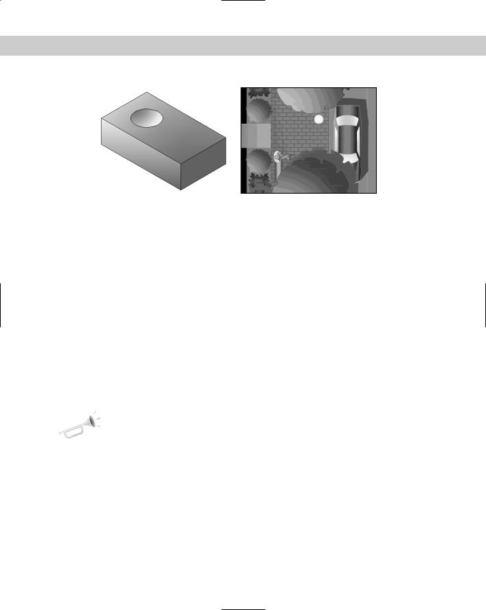
See Figure 16-25 for an example of some gradient fills. You could turn off the boundary layer for a more realistic look.
470 Part II Drawing in Two Dimensions
Figure 16-25: These gradients give the illusion of light shining from the left. (Refer to Figure 8-26, which shows the original isometric drawing without the gradients.)
Thanks to James Wedding for permission to use this drawing from Jones & Boyd, Inc.
Editing hatches
To edit a hatch pattern, including a solid or gradient, double-click it. The Hatch Edit dialog box opens. You can also choose Modify Object Hatch and then select a hatch object.
The Hatch Edit dialog box is exactly the same as the Hatch and Gradient dialog box, except that not all of the options are available. You can use this dialog box to change any of the hatch properties. You can change the boundary style on the expanded area of the dialog box. You can also preview the hatch. After you make your changes, click Apply to return to your drawing.
Because hatches are associative (unless you explode them or choose to create them as nonassociative), when you edit their boundaries, they adjust to fit the new boundary. However, if the new boundary is no longer closed, the hatch may lose its associativity, and you see the Hatch boundary associativity removed warning message.
By default, object snaps don’t work with hatch lines. This prevents you from accidentally drawing to a hatch line instead of a nearby object. If you want to snap to hatch lines, choose Tools Options, click the Drafting tab, and uncheck the Ignore Hatch Objects checkbox. Click OK to return to your drawing.
New |
You can now easily obtain the area of a hatch in the Properties palette. Select a hatch and |
Feature |
open the Properties palette. Look for the Area item in the Geometry section. You can also |
|
|
|
recreate the boundary of any hatch as a polyline or region. Edit the hatch and choose |
|
Recreate Boundary in the Edit Hatch dialog box. You can use this feature to create a bound- |
|
ary for a hatch if you have deleted it. |
You can also edit a gradient (AutoCAD only) in the Properties palette. Choose Properties on the Standard toolbar and use the items in the Pattern section. You can change the colors, angle, type, and whether it is centered.
You may find it difficult to select solid fill hatches. In some locations, you can pick the solid hatch, while at other points, you get the Other corner: prompt, meaning that no object was found. Try a crossing window. If necessary, try a crossing window at the edge of the hatch. This always selects the solid hatch but also selects the boundary. Hatches have a grip at their center. If you can find the grip and include it in the window, you can easily select the solid hatch.
Chapter 16 Drawing Complex Objects 471
Tip
On the
CD-ROM
You can trim hatches. Choose any object that crosses the hatch as the cutting edge and then select the hatch (on the side that you want to trim) as the object to trim. Chapter 10 covers trimming objects.
The drawing used in the following exercise on creating and editing hatches, ab16-f.dwg, is in the Drawings folder on the CD-ROM.
STEPS: Creating and Editing Hatches
1.Open ab16-f.dwg from your CD-ROM.
2.Save the file as ab16-06.dwg in your AutoCAD Bible folder.
3.Choose Hatch from the Draw toolbar. On the Hatch tab of the Hatch and Gradient dialog box, choose ANSI35 from the Pattern drop-down list. From the Scale drop-
down list, choose 0.5. Click Add: Select Objects.
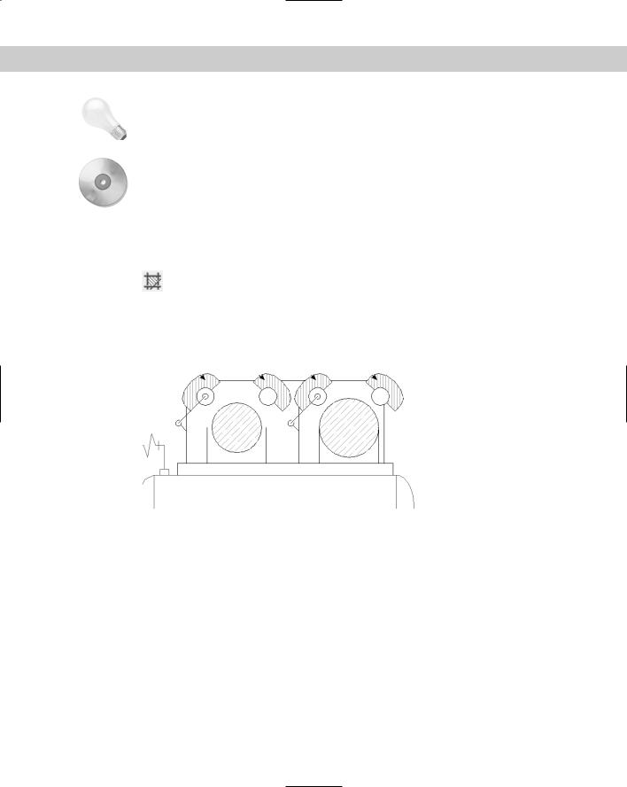
4.You’re now back in your drawing. Pick the two large circles in Figure 16-26. Right-click and choose Preview. Press Esc to return to the dialog box. Click OK to create the hatch and end the BHATCH command.
1 2 3 4
Figure 16-26: The result after editing the two hatches.
5.Again choose Hatch from the Draw toolbar. From the Type drop-down list, choose Userdefined. Set the angle to 135 and the spacing to 0.05.
6.Choose Add: Pick Points. In your drawing, pick points 1, 2, 3, and 4 in Figure 16-26. Right-click and choose Preview. Right-click again to create the hatch and end the BHATCH command.
7.Click the circumference of the left large circle. (If necessary, zoom in to avoid selecting
the hatching.) Pick the top grip to make it hot. At the Specify stretch point or [Base Point/Copy/Undo/eXit]: prompt, type .35 . Press Esc to remove the grips.
8.Double-click one of the hatches at the top of the model. Notice that this action selects all of the hatches because they were created with one command. In the Hatch Edit dialog box that opens, change the angle to 90 and the spacing to 0.04. Click OK. Your drawing should look like Figure 16-26.
9.Save your drawing.