

- •Contents
- •Contents at a Glance
- •Acknowledgments
- •Preface
- •Is This Book for You?
- •How This Book Is Organized
- •How to Use This Book
- •Doing the Exercises
- •Conventions Used in This Book
- •What the Icons Mean
- •About the CD-ROM
- •Other Information
- •Contacting the Author
- •Foreword
- •Credits
- •About the Author
- •Summary
- •AutoCAD’s Advantages
- •Comparing AutoCAD and AutoCAD LT
- •Starting AutoCAD and AutoCAD LT
- •Creating a New Drawing
- •Using the AutoCAD and AutoCAD LT Interface
- •Creating a New Folder
- •Using the Interface
- •Saving a Drawing
- •Closing a Drawing and Exiting from AutoCAD and AutoCAD LT
- •Summary
- •Creating a New Drawing from a Template
- •Working with Templates
- •Opening a Drawing with Default Settings
- •Opening an Existing Drawing
- •Using an Existing Drawing as a Prototype
- •Saving a Drawing Under a New Name
- •Summary
- •The Command Line and Dynamic Input
- •Command Techniques
- •Of Mice and Pucks
- •Getting Help
- •Summary
- •Typing Coordinates
- •Displaying Coordinates
- •Picking Coordinates on the Screen
- •Overriding Coordinate Settings
- •Locating Points
- •Summary
- •Choosing Unit Types
- •Drawing Limits
- •Understanding Scales
- •Creating a Title Block
- •Specifying Common Setup Options
- •Customizing with the MVSETUP Command
- •Using the Setup Wizards
- •Summary
- •Using the LINE Command
- •Drawing Rectangles
- •Drawing Polygons
- •Creating Construction Lines
- •Creating Rays
- •Summary
- •Drawing Circles
- •Drawing Arcs
- •Creating Ellipses and Elliptical Arcs
- •Making Donuts
- •Placing Points
- •Summary
- •Panning
- •Using the ZOOM Command
- •Using Aerial View
- •Saving Named Views
- •Working with Tiled Viewports
- •Using Snap Rotation
- •Understanding User Coordinate Systems
- •Creating Isometric Drawings
- •Summary
- •Editing a Drawing
- •Selecting Objects
- •Summary
- •Copying and Moving Objects
- •Resizing Commands
- •Using Construction Commands
- •Creating a Revision Cloud
- •Hiding Objects with a Wipeout
- •Double-Clicking to Edit Objects
- •Grips
- •Editing with the Properties Palette
- •Selection Filters
- •Groups
- •Summary
- •Working with Layers
- •Changing Object Color, Linetype, and Lineweight
- •Working with Linetype Scales
- •Importing Layers and Linetypes from Other Drawings
- •Matching Properties
- •Summary
- •Drawing-Level Information
- •Object-Level Information
- •Measurement Commands
- •AutoCAD’s Calculator
- •Summary
- •Creating Single-Line Text
- •Understanding Text Styles
- •Creating Multiline Text
- •Creating Tables
- •Inserting Fields
- •Managing Text
- •Finding Text in Your Drawing
- •Checking Your Spelling
- •Customizing the spelling dictionary
- •Summary
- •Working with Dimensions
- •Drawing Linear Dimensions
- •Drawing Aligned Dimensions
- •Creating Baseline and Continued Dimensions
- •Dimensioning Arcs and Circles
- •Dimensioning Angles
- •Creating Ordinate Dimensions
- •Drawing Leaders
- •Using Quick Dimension
- •Editing Dimensions
- •Summary
- •Understanding Dimension Styles
- •Defining a New Dimension Style
- •Changing Dimension Styles
- •Creating Geometric Tolerances
- •Summary
- •Creating and Editing Polylines
- •Drawing and Editing Splines
- •Creating Regions
- •Creating Boundaries
- •Creating Hatches
- •Creating and Editing Multilines
- •Creating Dlines
- •Using the SKETCH Command
- •Digitizing Drawings with the TABLET Command
- •Summary
- •Preparing a Drawing for Plotting or Printing
- •Creating a Layout in Paper Space
- •Working with Plot Styles
- •Plotting a Drawing
- •Summary
- •Combining Objects into Blocks
- •Inserting Blocks and Files into Drawings
- •Managing Blocks
- •Creating and Using Dynamic Blocks
- •Using Windows Features
- •Working with Attributes
- •Summary
- •Understanding External References
- •Editing an Xref within Your Drawing
- •Controlling Xref Display
- •Managing Xrefs
- •Summary
- •Preparing for Database Connectivity
- •Connecting to Your Database
- •Linking Data to Drawing Objects
- •Creating Labels
- •Querying with the Query Editor
- •Working with Query Files
- •Summary
- •Working with 3D Coordinates
- •Using Elevation and Thickness
- •Working with the User Coordinate System
- •Summary
- •Working with the Standard Viewpoints
- •Using DDVPOINT
- •Working with the Tripod and Compass
- •Displaying a Quick Plan View
- •Shading Your Drawing
- •Using 3D Orbit
- •Using Tiled Viewports
- •Defining a Perspective View
- •Laying Out 3D Drawings
- •Summary
- •Drawing Surfaces with 3DFACE
- •Drawing Surfaces with PFACE
- •Creating Polygon Meshes with 3DMESH
- •Drawing Standard 3D Shapes
- •Drawing a Revolved Surface
- •Drawing an Extruded Surface
- •Drawing Ruled Surfaces
- •Drawing Edge Surfaces
- •Summary
- •Drawing Standard Shapes
- •Creating Extruded Solids
- •Drawing Revolved Solids
- •Creating Complex Solids
- •Sectioning and Slicing Solids
- •Using Editing Commands in 3D
- •Editing Solids
- •Listing Solid Properties
- •Summary
- •Understanding Rendering
- •Creating Lights
- •Creating Scenes
- •Working with Materials
- •Using Backgrounds
- •Doing the Final Render
- •Summary
- •Accessing Drawing Components with the DesignCenter
- •Accessing Drawing Content with Tool Palettes
- •Setting Standards for Drawings
- •Organizing Your Drawings
- •Working with Sheet Sets
- •Maintaining Security
- •Keeping Track of Referenced Files
- •Handling Errors and Crashes
- •Managing Drawings from Prior Releases
- •Summary
- •Importing and Exporting Other File Formats
- •Working with Raster Images
- •Pasting, Linking, and Embedding Objects
- •Summary
- •Sending Drawings
- •Opening Drawings from the Web
- •Creating Object Hyperlinks
- •Publishing Drawings
- •Summary
- •Working with Customizable Files
- •Creating Keyboard Shortcuts for Commands
- •Customizing Toolbars
- •Customizing Tool Palettes
- •Summary
- •Creating Macros with Script Files
- •Creating Slide Shows
- •Creating Slide Libraries
- •Summary
- •Creating Linetypes
- •Creating Hatch Patterns
- •Summary
- •Creating Shapes
- •Creating Fonts
- •Summary
- •Working with the Customization File
- •Customizing a Menu
- •Summary
- •Introducing Visual LISP
- •Getting Help in Visual LISP
- •Working with AutoLISP Expressions
- •Using AutoLISP on the Command Line
- •Creating AutoLISP Files
- •Summary
- •Creating Variables
- •Working with AutoCAD Commands
- •Working with Lists
- •Setting Conditions
- •Managing Drawing Objects
- •Getting Input from the User
- •Putting on the Finishing Touches
- •Summary
- •Understanding Local and Global Variables
- •Working with Visual LISP ActiveX Functions
- •Debugging Code
- •Summary
- •Starting to Work with VBA
- •Writing VBA Code
- •Getting User Input
- •Creating Dialog Boxes
- •Modifying Objects
- •Debugging and Trapping Errors
- •Moving to Advanced Programming
- •Summary
- •A Final Word
- •Installing AutoCAD and AutoCAD LT
- •Configuring and Using Workspaces
- •Configuring AutoCAD
- •Starting AutoCAD Your Way
- •Configuring a Plotter
- •Discovering AutoCAD and AutoCAD LT
- •Accessing Technical Support
- •Autodesk User Groups
- •Internet Resources
- •System Requirements
- •Using the CD-ROM with Microsoft Windows
- •What’s on the CD-ROM
- •Troubleshooting
- •Index
Chapter 16 Drawing Complex Objects 455
You can edit a spline in the Properties palette. It works similarly to editing a polyline. You can choose the fit points or the control points and change them.
Creating Regions
Regions are two-dimensional surfaces. They look like closed polylines, but your drawing can calculate more information from regions than from polylines, such as the centroid, moments of inertia, and other properties relating to mass. You can also create complex shapes by combining, subtracting, and intersecting regions. Although these commands are most often used for 3D drawing, they’re often used in 2D drawing as a preparation for 3D drawing.
You create a region from other objects. You can use closed polylines, closed splines, circles, ellipses, and combinations of lines, arcs, and elliptical arcs that create a closed shape. The shape cannot intersect itself like a figure 8.
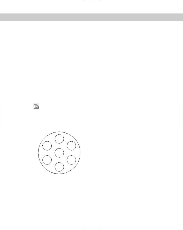
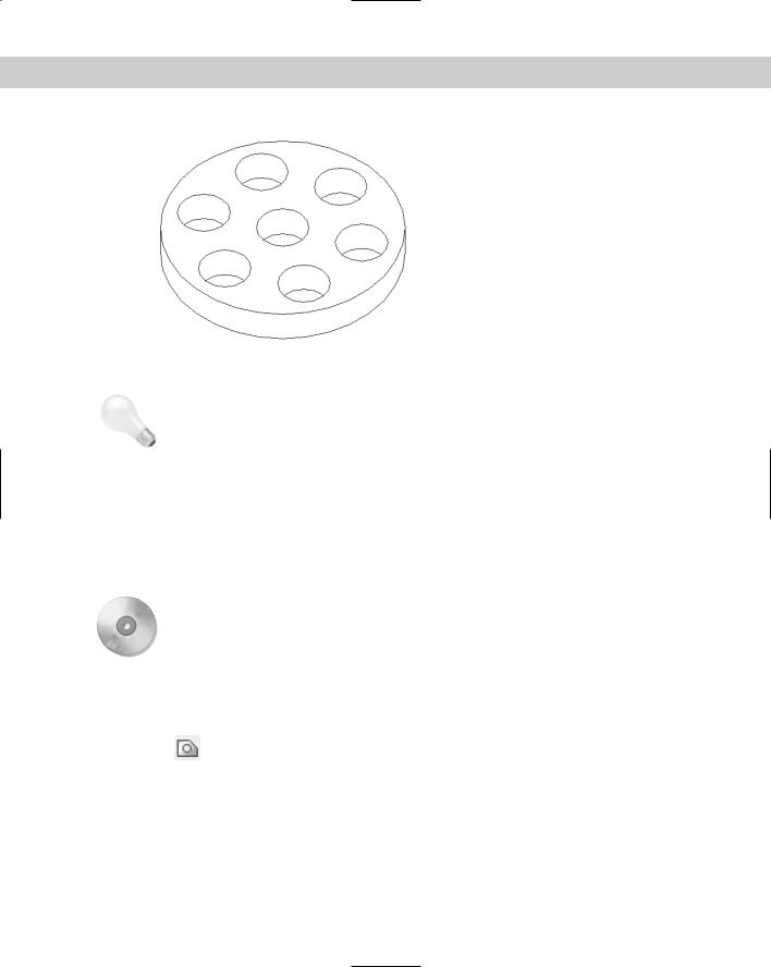
Figure 16-11 shows a complex region. Although it looks like a circle with seven circles inside it, it’s actually a circular surface with seven holes in it. When you select it, you can see that it’s one object. The real proof of the pudding is when you try to extrude it to create a 3D object out of it. You can then view it at an angle, hide background lines, and clearly see the holes, as shown in Figure 16-12.
To create a region, choose Region from the Draw toolbar. The prompt asks you to select objects. Select all of the objects and press Enter to end object selection. If all of the
objects create a closed, nonintersecting shape, the prompt tells you:
1 loop extracted.
1 Region created.
Figure 16-11: A complex region.
The original objects are deleted. If your objects aren’t perfectly end-to-end, the prompt merely states:
0 loops extracted.
0 Regions created.
456 Part II Drawing in Two Dimensions
Figure 16-12: A region can be used to create a complex 3D object.
Tip |
If you want to keep the original objects when converting closed shapes to a region, change |
|
the DELOBJ system variable to 0 (off) before you use the REGION command. The DELOBJ |
|
system variable deletes objects that are used to create other objects. |
The BOUNDARY command (see the next section) offers a way to create regions in situations where objects are not neatly drawn end to end.
If you had a hatch inside the objects, you lose hatch associativity. You can rehatch the region if you want.
You can combine, subtract, and intersect regions to create complex objects. The three commands to accomplish these functions are UNION, SUBTRACT, and INTERSECT. These commands are discussed in Chapter 24 because they’re most often used in 3D drafting.
On the |
The drawing used in the following exercise on creating regions, ab16-d.dwg, is in the |
CD-ROM |
Drawings folder on the CD-ROM. |
STEPS: Creating Regions
1.Open ab16-d.dwg from your CD-ROM.
2.Save the file as ab16-04.dwg in your AutoCAD Bible folder.
3.Choose Region from the Draw toolbar. At the Select Objects: prompt, use a selection window to select the entire model, shown in Figure 16-13. Press Enter
to end object selection. The prompt responds with this message:
7 loops extracted.
7 Regions created.
4. Save your drawing.
Chapter 16 Drawing Complex Objects 457
Figure 16-13: The outer profile and the six circles can all be turned into regions. The circles could then be subtracted from the outer profile to create a surface with six holes.
Creating Boundaries
The BOUNDARY command creates either polylines or regions from an enclosed area. This command has the capability of analyzing an area and ignoring intersecting lines that give the REGION command so much trouble. However, no spaces are allowed between objects.
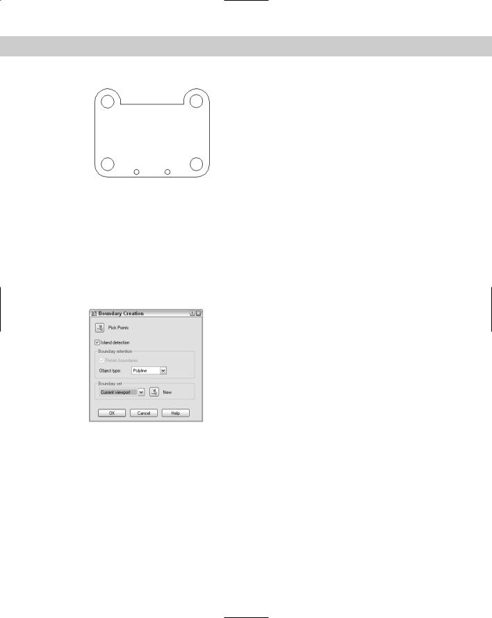
(Chapter 12 explains how to use the BOUNDARY command to calculate the area of a closed space.) Use the BOUNDARY command whenever you need to create a closed complex area. To create a boundary, choose Draw Boundary to open the Boundary Creation dialog box, shown in Figure 16-14.
Figure 16-14: The Boundary Creation dialog box.
Follow these steps:
1.If you want the command to detect internal closed areas, leave the Island Detection check box checked. Otherwise, uncheck this check box.
2.The Object Type drop-down list determines the type of object that BOUNDARY creates. Choose either Region or Polyline.
3.Choose the boundary set, which is the area to include in the analysis for the boundary. Usually, you can accept the default of Current viewport. However, if you have a very complex drawing, choose New to temporarily return to your drawing. Specify a window around the area that you want for the boundary set. The command then returns you to the dialog box.
458 Part II Drawing in Two Dimensions
4.To specify the enclosed area for the boundary, choose Pick Points. You return to your drawing with the Select internal point: prompt.
5.Pick any point inside the closed area that you want for your boundary. The command analyzes the area that you picked.
6.You then get a prompt for another internal point. If you want to create other boundaries, continue to pick internal points. Press Enter to end point selection.
The prompt informs you of how many regions or polylines it created, and then ends the command.
When BOUNDARY creates a region or polyline, the original objects are not deleted. You end up with a region or polyline on top of your original objects.
On the |
The drawing used in the following exercise on creating boundaries, ab16-e.dwg, is in the |
CD-ROM |
Drawings folder on the CD-ROM. |
STEPS: Creating Boundaries
1.Open ab16-e.dwg from your CD-ROM.
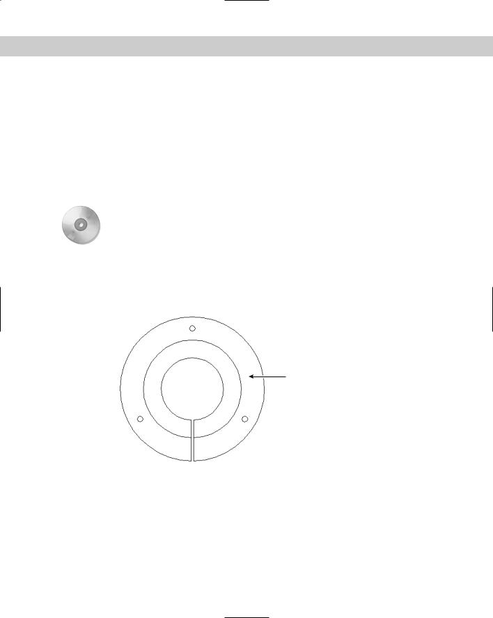
2.Save the file as ab16-05.dwg in your AutoCAD Bible folder. This is a bushing, shown in Figure 16-15.
1
 2
2
Figure 16-15: A bushing.
3.Choose Draw Boundary. In the Boundary Creation dialog box, choose Region as the Object type.
4.Choose Pick Points.
5.At the Select internal point: prompt, choose 1 in Figure 16-15.
6.Press Enter to end internal point selection. The prompt responds:
4 loops extracted.
4 Regions created. BOUNDARY created 4 regions