

- •Contents
- •Contents at a Glance
- •Acknowledgments
- •Preface
- •Is This Book for You?
- •How This Book Is Organized
- •How to Use This Book
- •Doing the Exercises
- •Conventions Used in This Book
- •What the Icons Mean
- •About the CD-ROM
- •Other Information
- •Contacting the Author
- •Foreword
- •Credits
- •About the Author
- •Summary
- •AutoCAD’s Advantages
- •Comparing AutoCAD and AutoCAD LT
- •Starting AutoCAD and AutoCAD LT
- •Creating a New Drawing
- •Using the AutoCAD and AutoCAD LT Interface
- •Creating a New Folder
- •Using the Interface
- •Saving a Drawing
- •Closing a Drawing and Exiting from AutoCAD and AutoCAD LT
- •Summary
- •Creating a New Drawing from a Template
- •Working with Templates
- •Opening a Drawing with Default Settings
- •Opening an Existing Drawing
- •Using an Existing Drawing as a Prototype
- •Saving a Drawing Under a New Name
- •Summary
- •The Command Line and Dynamic Input
- •Command Techniques
- •Of Mice and Pucks
- •Getting Help
- •Summary
- •Typing Coordinates
- •Displaying Coordinates
- •Picking Coordinates on the Screen
- •Overriding Coordinate Settings
- •Locating Points
- •Summary
- •Choosing Unit Types
- •Drawing Limits
- •Understanding Scales
- •Creating a Title Block
- •Specifying Common Setup Options
- •Customizing with the MVSETUP Command
- •Using the Setup Wizards
- •Summary
- •Using the LINE Command
- •Drawing Rectangles
- •Drawing Polygons
- •Creating Construction Lines
- •Creating Rays
- •Summary
- •Drawing Circles
- •Drawing Arcs
- •Creating Ellipses and Elliptical Arcs
- •Making Donuts
- •Placing Points
- •Summary
- •Panning
- •Using the ZOOM Command
- •Using Aerial View
- •Saving Named Views
- •Working with Tiled Viewports
- •Using Snap Rotation
- •Understanding User Coordinate Systems
- •Creating Isometric Drawings
- •Summary
- •Editing a Drawing
- •Selecting Objects
- •Summary
- •Copying and Moving Objects
- •Resizing Commands
- •Using Construction Commands
- •Creating a Revision Cloud
- •Hiding Objects with a Wipeout
- •Double-Clicking to Edit Objects
- •Grips
- •Editing with the Properties Palette
- •Selection Filters
- •Groups
- •Summary
- •Working with Layers
- •Changing Object Color, Linetype, and Lineweight
- •Working with Linetype Scales
- •Importing Layers and Linetypes from Other Drawings
- •Matching Properties
- •Summary
- •Drawing-Level Information
- •Object-Level Information
- •Measurement Commands
- •AutoCAD’s Calculator
- •Summary
- •Creating Single-Line Text
- •Understanding Text Styles
- •Creating Multiline Text
- •Creating Tables
- •Inserting Fields
- •Managing Text
- •Finding Text in Your Drawing
- •Checking Your Spelling
- •Customizing the spelling dictionary
- •Summary
- •Working with Dimensions
- •Drawing Linear Dimensions
- •Drawing Aligned Dimensions
- •Creating Baseline and Continued Dimensions
- •Dimensioning Arcs and Circles
- •Dimensioning Angles
- •Creating Ordinate Dimensions
- •Drawing Leaders
- •Using Quick Dimension
- •Editing Dimensions
- •Summary
- •Understanding Dimension Styles
- •Defining a New Dimension Style
- •Changing Dimension Styles
- •Creating Geometric Tolerances
- •Summary
- •Creating and Editing Polylines
- •Drawing and Editing Splines
- •Creating Regions
- •Creating Boundaries
- •Creating Hatches
- •Creating and Editing Multilines
- •Creating Dlines
- •Using the SKETCH Command
- •Digitizing Drawings with the TABLET Command
- •Summary
- •Preparing a Drawing for Plotting or Printing
- •Creating a Layout in Paper Space
- •Working with Plot Styles
- •Plotting a Drawing
- •Summary
- •Combining Objects into Blocks
- •Inserting Blocks and Files into Drawings
- •Managing Blocks
- •Creating and Using Dynamic Blocks
- •Using Windows Features
- •Working with Attributes
- •Summary
- •Understanding External References
- •Editing an Xref within Your Drawing
- •Controlling Xref Display
- •Managing Xrefs
- •Summary
- •Preparing for Database Connectivity
- •Connecting to Your Database
- •Linking Data to Drawing Objects
- •Creating Labels
- •Querying with the Query Editor
- •Working with Query Files
- •Summary
- •Working with 3D Coordinates
- •Using Elevation and Thickness
- •Working with the User Coordinate System
- •Summary
- •Working with the Standard Viewpoints
- •Using DDVPOINT
- •Working with the Tripod and Compass
- •Displaying a Quick Plan View
- •Shading Your Drawing
- •Using 3D Orbit
- •Using Tiled Viewports
- •Defining a Perspective View
- •Laying Out 3D Drawings
- •Summary
- •Drawing Surfaces with 3DFACE
- •Drawing Surfaces with PFACE
- •Creating Polygon Meshes with 3DMESH
- •Drawing Standard 3D Shapes
- •Drawing a Revolved Surface
- •Drawing an Extruded Surface
- •Drawing Ruled Surfaces
- •Drawing Edge Surfaces
- •Summary
- •Drawing Standard Shapes
- •Creating Extruded Solids
- •Drawing Revolved Solids
- •Creating Complex Solids
- •Sectioning and Slicing Solids
- •Using Editing Commands in 3D
- •Editing Solids
- •Listing Solid Properties
- •Summary
- •Understanding Rendering
- •Creating Lights
- •Creating Scenes
- •Working with Materials
- •Using Backgrounds
- •Doing the Final Render
- •Summary
- •Accessing Drawing Components with the DesignCenter
- •Accessing Drawing Content with Tool Palettes
- •Setting Standards for Drawings
- •Organizing Your Drawings
- •Working with Sheet Sets
- •Maintaining Security
- •Keeping Track of Referenced Files
- •Handling Errors and Crashes
- •Managing Drawings from Prior Releases
- •Summary
- •Importing and Exporting Other File Formats
- •Working with Raster Images
- •Pasting, Linking, and Embedding Objects
- •Summary
- •Sending Drawings
- •Opening Drawings from the Web
- •Creating Object Hyperlinks
- •Publishing Drawings
- •Summary
- •Working with Customizable Files
- •Creating Keyboard Shortcuts for Commands
- •Customizing Toolbars
- •Customizing Tool Palettes
- •Summary
- •Creating Macros with Script Files
- •Creating Slide Shows
- •Creating Slide Libraries
- •Summary
- •Creating Linetypes
- •Creating Hatch Patterns
- •Summary
- •Creating Shapes
- •Creating Fonts
- •Summary
- •Working with the Customization File
- •Customizing a Menu
- •Summary
- •Introducing Visual LISP
- •Getting Help in Visual LISP
- •Working with AutoLISP Expressions
- •Using AutoLISP on the Command Line
- •Creating AutoLISP Files
- •Summary
- •Creating Variables
- •Working with AutoCAD Commands
- •Working with Lists
- •Setting Conditions
- •Managing Drawing Objects
- •Getting Input from the User
- •Putting on the Finishing Touches
- •Summary
- •Understanding Local and Global Variables
- •Working with Visual LISP ActiveX Functions
- •Debugging Code
- •Summary
- •Starting to Work with VBA
- •Writing VBA Code
- •Getting User Input
- •Creating Dialog Boxes
- •Modifying Objects
- •Debugging and Trapping Errors
- •Moving to Advanced Programming
- •Summary
- •A Final Word
- •Installing AutoCAD and AutoCAD LT
- •Configuring and Using Workspaces
- •Configuring AutoCAD
- •Starting AutoCAD Your Way
- •Configuring a Plotter
- •Discovering AutoCAD and AutoCAD LT
- •Accessing Technical Support
- •Autodesk User Groups
- •Internet Resources
- •System Requirements
- •Using the CD-ROM with Microsoft Windows
- •What’s on the CD-ROM
- •Troubleshooting
- •Index
Chapter 14 Drawing Dimensions 383
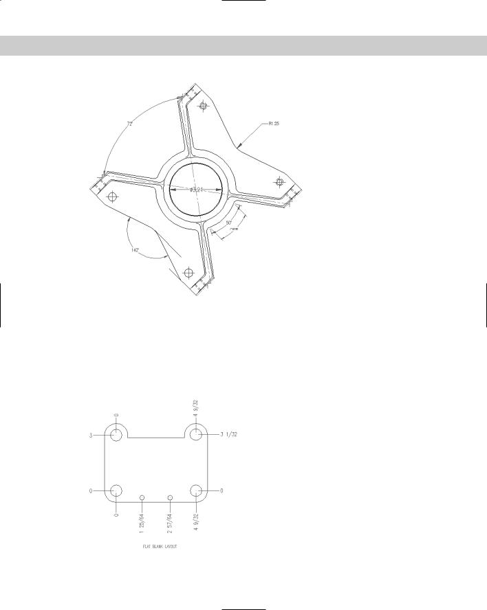
Figure 14-19: The bearing housing with center marks, radial and diameter dimensions, arc length, and angular dimensions.
Creating Ordinate Dimensions
Ordinate dimensions are used in mechanical drawing. They dimension an object by labeling X or Y coordinates based on a 0,0 coordinate placed somewhere on the model. Figure 14-20 shows a drawing with some ordinate dimensions.
Figure 14-20: Ordinate dimensions in a mechanical drawing of a tension arm for a commercial dryer.
384 Part II Drawing in Two Dimensions
To place the 0,0 coordinate on the model, choose Tools Move UCS. At the prompt, pick a point on the model, using object snaps for an exact measurement. If you want to check the UCS, choose View Display UCS Icon Origin. Also make sure that On is checked. As long as there is room, the UCS icon moves to the new 0,0 coordinate.
To create an ordinate dimension, choose Ordinate Dimension from the Dimension toolbar. At the Specify feature location: prompt, pick the part of the model that
you want to dimension. Running object snaps with OSNAP turned on makes this an easy task.
At the Specify leader endpoint or [Xdatum/Ydatum/Mtext/Text/Angle]: prompt, pick the endpoint for the leader. The location where you pick the leader endpoint determines which coordinate to dimension — the X coordinate (Xdatum) or Y coordinate (Ydatum). Pick the leader endpoint perpendicular from the coordinate’s axis that you want to measure. To measure an X coordinate, move up or down from the feature you selected. To measure a Y coordinate, move left or right to pick the leader endpoint.
Usually you work with ORTHO on to create straight lines. If you need to create bent lines to avoid previously drawn dimensions, turn ORTHO off. If you pick a leader endpoint at a
nonorthogonal angle from the feature, you may need to force the measurement of the coordinate that you want using either the Xdatum or Ydatum option. Use the MText option to open the In-Place Text Editor and edit the dimension text. Use the Text option to change all of the text on the command line.
To perfectly line up the dimensions, when specifying the leader endpoint, use object tracking to track the endpoint of the previous leader. You can also turn on SNAP.
On the |
The drawing used in the following exercise on drawing ordinate dimensions, ab14-d.dwg, |
CD-ROM |
is in the Drawings folder on the CD-ROM. |
STEPS: Drawing Ordinate Dimensions
1.Open ab14-d.dwg from your CD-ROM.
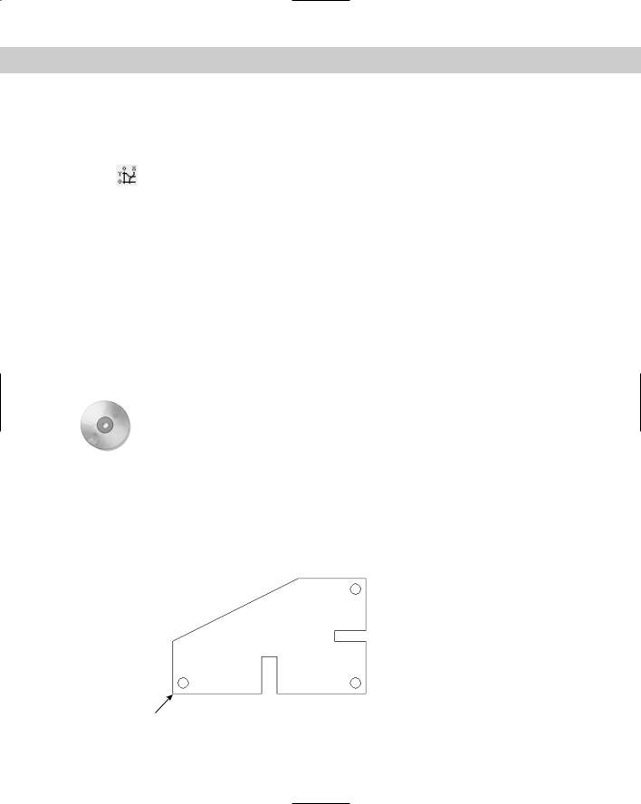
2.Save the file as ab14-05.dwg in your AutoCAD Bible folder. This drawing shows a simple sheet-metal template, as shown in Figure 14-21. Snap should be on. Set a snap distance of 0.25 units. Right-click the SNAP button on the status bar and make sure that grid snap is on. If the Dimension toolbar isn’t visible, right-click any toolbar and check Dimension.
1
Figure 14-21: A sheet-metal template.
Chapter 14 Drawing Dimensions 385
3.Choose Tools Move UCS. At the Origin point <0,0,0>: prompt, pick 1 in Figure 14-21.
4.Choose Ordinate Dimension from the Dimension toolbar. At the Specify feature location: prompt, choose 1 in Figure 14-21. At the Specify leader endpoint
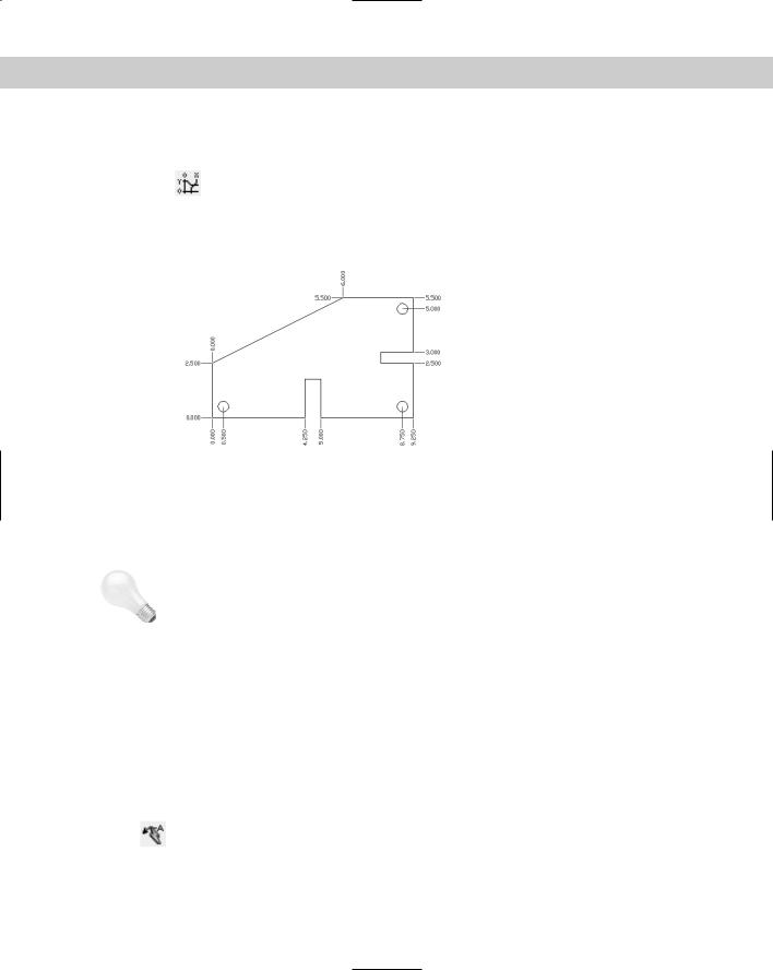
or [Xdatum/Ydatum/Mtext/Text/Angle]: prompt, pick a point 0.5 units to the left of 1, as shown in Figure 14-22. (Because Snap is on, this is easy. If necessary, press F6 until you get polar coordinates to display in the lower-left area of the drawing screen.)
Figure 14-22: The dimensioned template.
5.Repeat the DIMORDINATE command. At the Specify feature location: prompt, choose 1 in Figure 14-21. At the Specify leader endpoint or [Xdatum/Ydatum/ Mtext/Text/Angle]: prompt, pick a point 0.5 units below 1.
6.Continue to dimension the drawing, using Figure 14-22 as a guide.
Tip |
Type multiple dimordinate to automatically repeat the command. Press Esc when you |
|
no longer need the command. |
7. Save your drawing.
Drawing Leaders
Leaders are lines pointing to objects. At the end of a leader, you place any text that you want. Use leaders to label objects or provide explanatory text. Leaders are not associative; that is, AutoCAD and AutoCAD LT do not calculate dimension text. Figure 14-23 shows two leaders.
The QLEADER command provides a simple, easy-to-use method of creating leaders. The Leader Settings dialog box lets you specify how you want your leaders to appear. The older LEADER command is still available from the command line.
To create a leader, choose Quick Leader from the Dimension toolbar. At the Specify first leader point, or [Settings] <Settings>: prompt, if you want to specify
the leader settings, press Enter or right-click and choose Settings to open the Leader Settings dialog box.
386 Part II Drawing in Two Dimensions
Figure 14-23: Using leaders to point to objects and add explanatory text.
Using the Leader Settings dialog box
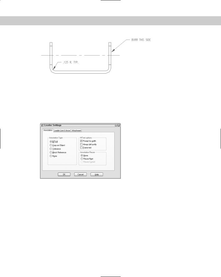
The Leader Settings dialog box is shown in Figure 14-24 with the Annotation tab displayed. Here you customize how you want your leaders to work so that when you actually create them, they automatically look the way you want. These settings determine what prompts you see after you specify all of the points of the leader. You can always change these settings at the first prompt of the QLEADER command.
Figure 14-24: The Annotation tab of the Leader
Settings dialog box.
The Annotation tab
The Annotation tab includes settings about what goes at the end of the leader. In the Annotation Type section of the dialog box, choose the type of annotation:
The default is MText, which creates multiline text.
Choose Copy an Object to have the QLEADER command prompt you to copy an existing object in your drawing, whether single-line text, multiline text, a block, or a tolerance.
If you choose Tolerance, QLEADER opens the Tolerance dialog box so that you can create a tolerance control frame. (The next chapter covers control frames.)

Chapter 14 Drawing Dimensions 387
Choose Block Reference if you want QLEADER to prompt you to select an existing block (a group of objects that are treated as one object) for the annotation. You might have a block consisting of some text and special symbols that are hard to create from scratch each time. Some users put surface, tolerance, or other symbols at the ends of leaders.
Choose None to create a leader with no annotation.
If you chose MText, use the MText options section to specify how MText works. You have three choices:
Choose Prompt for Width if you want QLEADER to let you specify a bounding box or a width in units. The advantage of this option, which is on by default, is that QLEADER wraps the leader text so that it doesn’t get too long if you decide to get verbose.
Choose Always Left Justify if you don’t want to set a width, and you want to have QLEADER always left-justify text.
Choose Frame text if you want a box around the text.
The Annotation Reuse section enables you to clone your leader annotation. To reuse the text you’re about to create, choose Reuse Next. QLEADER automatically uses it for subsequent leaders. (After you use this option, it is automatically changed to Reuse Current.)
The Leader Line & Arrow tab
The lines and arrows of a leader determine the structure of the leader. Use the Leader
Line & Arrow tab, shown in Figure 14-25, to specify how you want the lines and arrow of the leader to look.
Figure 14-25: The Leader Line & Arrow tab of the
Leader Settings dialog box.
In the Leader Line section, choose either Straight or Spline leader lines. The number of points determines how many times QLEADER displays the Specify next point: prompt. By setting a maximum, you can streamline the process of creating leaders and avoid ungainly looking leader lines with many segments. However, you can’t set the maximum to less than two.
388 Part II Drawing in Two Dimensions
In the Arrowhead section, use the drop-down list to choose an arrowhead style. The picture shown of each type of arrowhead helps you decide.
Use the Angle Constraints section to control the possible angle of the first and second leader lines to conform to standards in your industry or your sense of aesthetics.
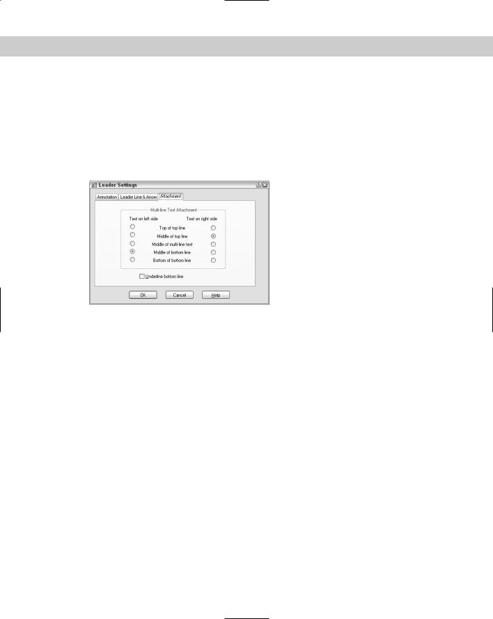
The Attachment tab
You usually place text at the end of a leader. Use the Attachment tab, shown in Figure 14-26, to specify how MText is attached to the leader line.
Figure 14-26: The Attachment tab of the Leader
Settings dialog box.
The Attachment tab contains two columns of buttons. The left column sets the attachment for leaders that you draw from right to left. The arrow is to the right, and the text is therefore on the left of the leader. By default, the leader line points to the middle of the bottom line of text — that is, to the middle of the last character of the text.
The right column sets the attachment for leaders that you draw from left to right. The arrow is to the left, and the text is on the right of the leader. By default, the leader line points to the middle of the top line of text — that is, to the middle of the first character of the text.
Here are your choices for text on both the left and the right:
Top of top line: The leader line meets the text at the top of the first line of text. The line will point to the top of an uppercase letter.
Middle of top line: The leader line meets the text at the middle of the first line of text, which is halfway between the top and the bottom of an uppercase letter.
Middle of multi-line text: The leader line meets the text at the middle of the invisible bounding box containing all the text.
Middle of bottom line: The leader line meets the text at the middle of the bottom line of text.
Bottom of bottom line: The leader line meets the text at the bottom of the bottom line of text.
Chapter 14 Drawing Dimensions 389
Check Underline Bottom Line to place a line under the bottom line of text. After you’ve completed the settings in the Leader Settings dialog box, click OK. You now continue with the QLEADER command.
The Express Tools include the QLDETACHSET command, which detaches a leader’s annotation from the leader line, to create two separate objects. Choose Express Dimension Leader Tools Detach Leaders from Annotation. QLATTACH attaches leaders and MText objects. Choose Express Dimension Leader Tools Attach Leader to Annotation. For information about installing Express Tools, see Appendix A.
Creating a leader
As mentioned earlier, when you choose Quick Leader from the Dimension toolbar, you see the Specify first leader point, or [Settings] <Settings>: prompt. You can continue directly to draw the leader or use the Settings option. If you use the Settings option, after you close the Leader Settings dialog box, you return to the original prompt. Now you can specify your first leader point, usually on or near the object that the leader text labels or explains. The starting point is usually indicated with an arrow.
The command continues with the Specify next point: prompt. You can continue to pick points, up to the limit specified on the Leader Line & Arrow tab of the Leader Settings dialog box. Usually you pick the endpoint of the leader before that limit. Press Enter to stop picking points of the leader.
If you selected the Prompt for Width option on the Annotation tab of the Leader Settings dialog box, QLEADER displays the Specify text width <0.0000>: prompt. You can pick a point, which displays a dashed line so that you can visually determine the width. Otherwise, type a width in units.
At the Enter first line of annotation text <Mtext>: prompt, you have two choices:
On the
CD-ROM
To use the current text style, type the first line of text on the command line. Press Enter at the end of the line. QLEADER displays the Enter next line of annotation text: prompt. You can continue to type in new lines of text. Press Enter to end the command.
To open the In-Place Text Editor, press Enter. You then type your annotation text. You have the advantage of being able to format the text as you work. Click OK to close the Text Editor and complete the leader.
The drawing used in the following exercise on drawing leaders, ab14-e.dwg, is in the Drawings folder on the CD-ROM.
STEPS: Drawing Leaders
1.Open ab14-e.dwg from your CD-ROM.
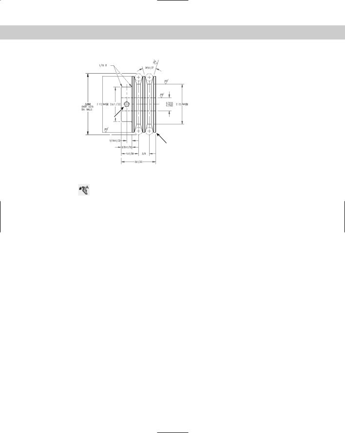
2.Save the file as ab14-06.dwg in your AutoCAD Bible folder. This is a drawing of a set of pulleys, as shown in Figure 14-27. If the Dimension toolbar isn’t visible, right-click any toolbar and check Dimension. OSNAP should be turned off.
390 Part II Drawing in Two Dimensions
3
1
4 |
2 |
Figure 14-27: A set of pulleys.
3.Choose Quick Leader from the Dimension toolbar. At the Specify first leader point, or [Settings] <Settings>: prompt, right-click and choose Settings.
Click the Attachment tab and choose the Middle of Multi-Line Text option for both text on the left and on the right. Click OK.
4.Follow the prompts:
Specify first leader point, or [Settings]<Settings>: Pick 1 in Figure 14-27 (near but not on the drawing object).
Specify next point: Pick 2. Specify next point: Specify text width <0>: 2
Enter first line of annotation text <Mtext>: BREAK EDGES Enter next line of annotation text: TYP (8) PLACES Enter next line of annotation text:
This action places the leader.
5.Repeat the QLEADER command. Pick points 3 and then 4 in Figure 14-27. Right-click or press Enter. At the Specify text width <2>: prompt, press Enter to use the same width as previously. At the Enter first line of annotation text <Mtext>: prompt, type DRILL ‘F’ HOLE. Press Enter twice to end the command and place the leader.
6.Save your drawing. It should look like Figure 14-28.