

- •Contents
- •Contents at a Glance
- •Acknowledgments
- •Preface
- •Is This Book for You?
- •How This Book Is Organized
- •How to Use This Book
- •Doing the Exercises
- •Conventions Used in This Book
- •What the Icons Mean
- •About the CD-ROM
- •Other Information
- •Contacting the Author
- •Foreword
- •Credits
- •About the Author
- •Summary
- •AutoCAD’s Advantages
- •Comparing AutoCAD and AutoCAD LT
- •Starting AutoCAD and AutoCAD LT
- •Creating a New Drawing
- •Using the AutoCAD and AutoCAD LT Interface
- •Creating a New Folder
- •Using the Interface
- •Saving a Drawing
- •Closing a Drawing and Exiting from AutoCAD and AutoCAD LT
- •Summary
- •Creating a New Drawing from a Template
- •Working with Templates
- •Opening a Drawing with Default Settings
- •Opening an Existing Drawing
- •Using an Existing Drawing as a Prototype
- •Saving a Drawing Under a New Name
- •Summary
- •The Command Line and Dynamic Input
- •Command Techniques
- •Of Mice and Pucks
- •Getting Help
- •Summary
- •Typing Coordinates
- •Displaying Coordinates
- •Picking Coordinates on the Screen
- •Overriding Coordinate Settings
- •Locating Points
- •Summary
- •Choosing Unit Types
- •Drawing Limits
- •Understanding Scales
- •Creating a Title Block
- •Specifying Common Setup Options
- •Customizing with the MVSETUP Command
- •Using the Setup Wizards
- •Summary
- •Using the LINE Command
- •Drawing Rectangles
- •Drawing Polygons
- •Creating Construction Lines
- •Creating Rays
- •Summary
- •Drawing Circles
- •Drawing Arcs
- •Creating Ellipses and Elliptical Arcs
- •Making Donuts
- •Placing Points
- •Summary
- •Panning
- •Using the ZOOM Command
- •Using Aerial View
- •Saving Named Views
- •Working with Tiled Viewports
- •Using Snap Rotation
- •Understanding User Coordinate Systems
- •Creating Isometric Drawings
- •Summary
- •Editing a Drawing
- •Selecting Objects
- •Summary
- •Copying and Moving Objects
- •Resizing Commands
- •Using Construction Commands
- •Creating a Revision Cloud
- •Hiding Objects with a Wipeout
- •Double-Clicking to Edit Objects
- •Grips
- •Editing with the Properties Palette
- •Selection Filters
- •Groups
- •Summary
- •Working with Layers
- •Changing Object Color, Linetype, and Lineweight
- •Working with Linetype Scales
- •Importing Layers and Linetypes from Other Drawings
- •Matching Properties
- •Summary
- •Drawing-Level Information
- •Object-Level Information
- •Measurement Commands
- •AutoCAD’s Calculator
- •Summary
- •Creating Single-Line Text
- •Understanding Text Styles
- •Creating Multiline Text
- •Creating Tables
- •Inserting Fields
- •Managing Text
- •Finding Text in Your Drawing
- •Checking Your Spelling
- •Customizing the spelling dictionary
- •Summary
- •Working with Dimensions
- •Drawing Linear Dimensions
- •Drawing Aligned Dimensions
- •Creating Baseline and Continued Dimensions
- •Dimensioning Arcs and Circles
- •Dimensioning Angles
- •Creating Ordinate Dimensions
- •Drawing Leaders
- •Using Quick Dimension
- •Editing Dimensions
- •Summary
- •Understanding Dimension Styles
- •Defining a New Dimension Style
- •Changing Dimension Styles
- •Creating Geometric Tolerances
- •Summary
- •Creating and Editing Polylines
- •Drawing and Editing Splines
- •Creating Regions
- •Creating Boundaries
- •Creating Hatches
- •Creating and Editing Multilines
- •Creating Dlines
- •Using the SKETCH Command
- •Digitizing Drawings with the TABLET Command
- •Summary
- •Preparing a Drawing for Plotting or Printing
- •Creating a Layout in Paper Space
- •Working with Plot Styles
- •Plotting a Drawing
- •Summary
- •Combining Objects into Blocks
- •Inserting Blocks and Files into Drawings
- •Managing Blocks
- •Creating and Using Dynamic Blocks
- •Using Windows Features
- •Working with Attributes
- •Summary
- •Understanding External References
- •Editing an Xref within Your Drawing
- •Controlling Xref Display
- •Managing Xrefs
- •Summary
- •Preparing for Database Connectivity
- •Connecting to Your Database
- •Linking Data to Drawing Objects
- •Creating Labels
- •Querying with the Query Editor
- •Working with Query Files
- •Summary
- •Working with 3D Coordinates
- •Using Elevation and Thickness
- •Working with the User Coordinate System
- •Summary
- •Working with the Standard Viewpoints
- •Using DDVPOINT
- •Working with the Tripod and Compass
- •Displaying a Quick Plan View
- •Shading Your Drawing
- •Using 3D Orbit
- •Using Tiled Viewports
- •Defining a Perspective View
- •Laying Out 3D Drawings
- •Summary
- •Drawing Surfaces with 3DFACE
- •Drawing Surfaces with PFACE
- •Creating Polygon Meshes with 3DMESH
- •Drawing Standard 3D Shapes
- •Drawing a Revolved Surface
- •Drawing an Extruded Surface
- •Drawing Ruled Surfaces
- •Drawing Edge Surfaces
- •Summary
- •Drawing Standard Shapes
- •Creating Extruded Solids
- •Drawing Revolved Solids
- •Creating Complex Solids
- •Sectioning and Slicing Solids
- •Using Editing Commands in 3D
- •Editing Solids
- •Listing Solid Properties
- •Summary
- •Understanding Rendering
- •Creating Lights
- •Creating Scenes
- •Working with Materials
- •Using Backgrounds
- •Doing the Final Render
- •Summary
- •Accessing Drawing Components with the DesignCenter
- •Accessing Drawing Content with Tool Palettes
- •Setting Standards for Drawings
- •Organizing Your Drawings
- •Working with Sheet Sets
- •Maintaining Security
- •Keeping Track of Referenced Files
- •Handling Errors and Crashes
- •Managing Drawings from Prior Releases
- •Summary
- •Importing and Exporting Other File Formats
- •Working with Raster Images
- •Pasting, Linking, and Embedding Objects
- •Summary
- •Sending Drawings
- •Opening Drawings from the Web
- •Creating Object Hyperlinks
- •Publishing Drawings
- •Summary
- •Working with Customizable Files
- •Creating Keyboard Shortcuts for Commands
- •Customizing Toolbars
- •Customizing Tool Palettes
- •Summary
- •Creating Macros with Script Files
- •Creating Slide Shows
- •Creating Slide Libraries
- •Summary
- •Creating Linetypes
- •Creating Hatch Patterns
- •Summary
- •Creating Shapes
- •Creating Fonts
- •Summary
- •Working with the Customization File
- •Customizing a Menu
- •Summary
- •Introducing Visual LISP
- •Getting Help in Visual LISP
- •Working with AutoLISP Expressions
- •Using AutoLISP on the Command Line
- •Creating AutoLISP Files
- •Summary
- •Creating Variables
- •Working with AutoCAD Commands
- •Working with Lists
- •Setting Conditions
- •Managing Drawing Objects
- •Getting Input from the User
- •Putting on the Finishing Touches
- •Summary
- •Understanding Local and Global Variables
- •Working with Visual LISP ActiveX Functions
- •Debugging Code
- •Summary
- •Starting to Work with VBA
- •Writing VBA Code
- •Getting User Input
- •Creating Dialog Boxes
- •Modifying Objects
- •Debugging and Trapping Errors
- •Moving to Advanced Programming
- •Summary
- •A Final Word
- •Installing AutoCAD and AutoCAD LT
- •Configuring and Using Workspaces
- •Configuring AutoCAD
- •Starting AutoCAD Your Way
- •Configuring a Plotter
- •Discovering AutoCAD and AutoCAD LT
- •Accessing Technical Support
- •Autodesk User Groups
- •Internet Resources
- •System Requirements
- •Using the CD-ROM with Microsoft Windows
- •What’s on the CD-ROM
- •Troubleshooting
- •Index
276 Part II Drawing in Two Dimensions
6.Choose Layer Properties Manager from the Layers toolbar to open the Layer Properties
Manager again. Choose Mydims. Click it a second time so that the name of the layer is highlighted. Type Titles . The name of the layer is changed. Click OK.
7.Start the ERASE command and pick anywhere on the title block (it is all one object) and the three labels FRONT, TOP, and RIGHT SIDE. Press Enter to end the command.
8.Choose Layer Properties Manager from the Layers toolbar again. Notice that the Titles layer is not on the list because this layer no longer starts with the letter M. In the Filter Tree panel, click All to display all of the layers.
9.Scroll down the list of layers and choose Titles. You can see that its Status icon is off, indicating that the layer contains no objects. Click the Delete button. Click OK
to close the dialog box.
10. Save your drawing.
Changing Object Color, Linetype, and Lineweight
The properties of layers — color, linetype, lineweight — can also apply directly to objects. You can assign a color, linetype, and lineweight to an object. You can also set a current color, linetype, and lineweight so that all of the future objects that you draw have those properties, regardless of the properties assigned to their layer. In most cases, you should avoid assigning properties directly to objects because the organizational value of layers is lost.
Cross- |
You can also assign plot styles to objects. See Chapter 17 for more information. |
Reference |
|
Changing an object’s color
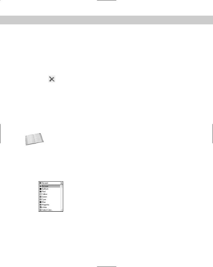
You can control an object’s color by using the Color Control drop-down list on the Properties toolbar, as shown in Figure 11-17. For more information about choosing colors, see “Assigning a color” earlier in this chapter. As with the Layer Control drop-down list, the Color Control drop-down list shows the color of any selected object. When you create a layer, assign it a color, and draw with that layer, the color is displayed as ByLayer.
Figure 11-17: The Color Control drop-down list on the Properties toolbar.
The ByLayer color means that the color of the object is taken from the color of the object’s layer. At the same time that you see the selected object’s color in the Color Control drop-down list, you can look over to the Layer Control drop-down list and confirm the color assignment of the object’s layer.
The ByBlock color creates objects by using color 7 (white or black, depending on the screen color), but if the objects are placed in a block, the block takes on the current color when inserted. (For information about blocks, see Chapter 18.)
Chapter 11 Organizing Drawings with Layers, Colors, Linetypes, and Lineweights |
277 |
The best way to organize a drawing is to assign colors by layer. It can be confusing if related elements, such as centerlines in a mechanical drawing, appear in different colors. Also, if you see another line with the same color and linetype as most centerlines, you may assume that it’s a centerline in the wrong place. It is standard practice to organize colors by layer.
Colors have a special significance because when you plot, you can assign colors to pens — although you can also use plot styles (see Chapter 17). If you use a color-based system, color is the basis that you use for plotting with various width pens or colors. You may want to temporarily change the color of an object to emphasize it in a plot or for some other reason. However, you should generally refrain from directly changing the color of objects.
If you need to change the color of an object, here are two ways to do it:
To change just an object’s color, select the object. Click the Color Control drop-down list and choose the color that you want.
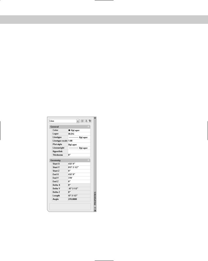
If you want to change other properties at the same time, select the object and choose Properties from the Standard toolbar. The Properties palette opens, as shown in Figure 11-18. In this window, you can change all of the properties of the object. To change the color, choose Color and click the drop-down arrow that appears. Choose the color that you want.
Figure 11-18: The Properties palette.
You can always change an object’s color back to ByLayer, using the same Color Control dropdown list.
278 Part II Drawing in Two Dimensions
Changing the current color
When you change the current color, all future objects are drawn using that color, regardless of their layer. In general, you should do this only when you have a special need for two objects to be on one layer but have different colors. An example might be text in a title block. You might want the text to have the same layer so that you can freeze it and thaw it (or turn it on and off) easily without having to remember that the text and title block are on two separate layers. If you also want part of the text to have a different color, change the current color before typing in that part of the text. Remember to change the current color back to ByLayer before drawing anything else.
To change the current color, make sure that no object is selected. Then click the Color dropdown list and choose the color that you want. To use a color not on the list, choose Select color to open the Select Color dialog box. (See the section “Assigning a color” earlier in this chapter for more information on assigning colors.) To change the current color back to ByLayer, click the Color drop-down list, and choose ByLayer. You have an opportunity to do an exercise on changing colors after the “Changing the current lineweight” section.
Changing an object’s linetype
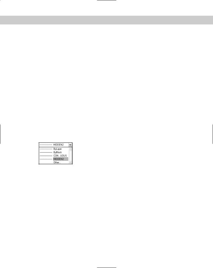
Linetypes work according to the same principles as colors. You can change the linetype of an existing object or objects. You can control an object’s linetype by using the Linetype Control drop-down list on the Properties toolbar, shown in Figure 11-19. The Linetype Control drop-down list shows the linetype of any selected object. When you create a layer, assign it a linetype, and draw with that layer, the linetype is displayed as ByLayer.
Figure 11-19: The Linetype Control drop-down list on the
Properties toolbar.
The ByLayer linetype simply means that the linetype of the object is taken from the linetype of the object’s layer.
The best way to organize a drawing is to assign linetypes by layer. It can be confusing if similar elements, such as plat borders in a surveyor’s drawing, appear in different linetypes. Also, if you see another line with the same color and linetype as most plat borders, you may assume that it’s a plat border in the wrong place. It is common practice to organize linetypes by layer.
If you need to change the linetype of an object, you have two options:
To change an object’s linetype, select the object. Click the Linetype Control drop-down list and choose the linetype that you want.
Select the object and choose Properties from the Standard toolbar. The Properties palette (refer to Figure 11-18) opens. To change an object’s linetype, click Linetype, and then click the drop-down arrow that appears. Choose from one of the linetypes.
You can always change an object’s linetype back to ByLayer, using the same Linetype Control drop-down list.

Chapter 11 Organizing Drawings with Layers, Colors, Linetypes, and Lineweights |
279 |
As discussed in the “Assigning a linetype” section earlier in this chapter, you may need to load a linetype before you can use it. To load a linetype, choose Linetype Control from the Properties toolbar. Scroll down to the bottom of the list and choose Other to open the Linetype Manager. Choose Load to open the Load or Reload Linetypes dialog box, choose the linetype file (if not the default), and choose the linetype that you want to load. Click OK. Choose the linetype again in the Linetype Manager and click OK to return to your drawing.
To filter the list of linetypes, choose from the Linetype Filters drop-down list box in the Linetype Manager.
Changing the current linetype
You can also change the current linetype. When you change the current linetype, all future objects that you draw have that linetype and are not drawn according to their layer’s assigned linetype. In general, you should do this only when you have a special need for two objects to be on one layer but have different linetypes. An example might be a table containing notes in one corner of a drawing. You might want the lines that make up the table to have the same layer so that you can freeze it and thaw it (or turn it on and off) easily without having to remember that the table is on two separate layers. If you also want some of the lines to have a different linetype, change the current linetype before adding those lines. Remember to change the current linetype back to ByLayer before drawing anything else.
To change the current linetype, click the Linetype drop-down list and choose the linetype that you want, first making sure that no objects are currently selected. To change the current linetype back to ByLayer, click the Linetype drop-down list and choose ByLayer.
Changing an object’s lineweight
Lineweights let you represent objects with varying line widths. The widths can represent the width of a pen in a pen plotter that will be used to plot that object. Lineweights can also be used as an organizational tool, to distinguish certain types of objects just as colors and linetypes do. Finally, you can use lineweights to represent the actual properties of objects, such as the width of wires in an electrical schematic.
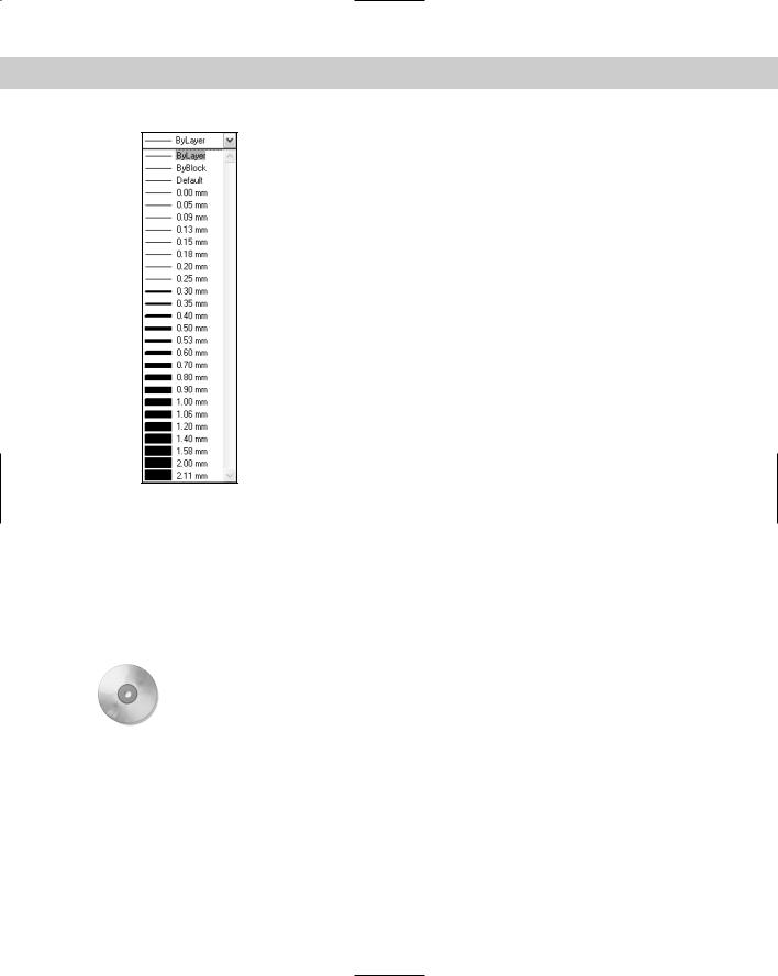
Lineweights work according to the same principles as colors and linetypes. You can control an object’s lineweight by using the Lineweight Control drop-down list on the Properties toolbar, as shown in Figure 11-20. The Lineweight Control drop-down list shows the lineweight of any selected object. When you create a layer, assign it a lineweight, and draw with that layer, the lineweight is displayed as ByLayer.
As with colors and linetypes, the best way to organize a drawing is to assign lineweights by layer. If you need to change the lineweight of an object, do one of the following:
Select the object. Click the Lineweight Control drop-down list and choose the lineweight that you want.
Select the object and choose Properties from the Standard toolbar. The Properties palette opens. To change an object’s lineweight, click Lineweight, and then click the drop-down arrow that appears. Choose from one of the lineweights.
280 Part II Drawing in Two Dimensions
Figure 11-20: The Lineweight drop-down list on the Properties toolbar.
Changing the current lineweight
You can also change the current lineweight. When you change the current lineweight, all future objects that you draw have that lineweight and are not drawn according to their layer’s assigned lineweight.
To change the current lineweight, click the Lineweight drop-down list and choose the lineweight that you want, first making sure that no objects are currently selected. To change the current lineweight back to ByLayer, click the Lineweight drop-down list and choose ByLayer.
On the |
The drawing used in the following exercise on changing colors, linetypes, and lineweights, |
CD-ROM |
ab11-d.dwg, is in the Drawings folder on the CD-ROM. |
STEPS: Changing Colors, Linetypes, and Lineweights
1.Open ab11-d.dwg from the CD-ROM.
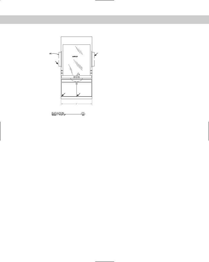
2.Save the file as ab11-04.dwg in your AutoCAD Bible folder. This is an elevation view of a lavatory cabinet, shown in Figure 11-21.
3.Pick one of the reflection lines in the mirror. Notice that the color is red but the layer’s color, as shown in the Layer Control drop-down list, is Magenta. Select all of the reflection lines. Click the Color Control drop-down list and choose ByLayer from the top of the list. Press Esc to remove the grips.
Chapter 11 Organizing Drawings with Layers, Colors, Linetypes, and Lineweights |
281 |
1
2
3 4
Figure 11-21: A lavatory cabinet.
Thanks to the Army Corps of Engineers for this drawing.
4.Select the green dimension at the bottom of the cabinet. (The dimension is all one object.) To make it more visible, click the Color Control drop-down list and choose Red. Press Esc to see the result.
5.Pick the lines at 1 and 2 in Figure 11-21. Click the Linetype Control drop-down list and choose the Hidden linetype. Press Esc so that the hidden lines are no longer selected.
6.Select the dashed arc that represents the bottom curvature of the sink. Click the Lineweight Control drop-down list and choose 0.30 mm. Press Esc. Click LWT on the status bar to turn on the display of lineweights and see the result.
7.Click the Color Control drop-down list box and choose Cyan to make it the current color.
8.Start the RECTANG command. Draw a rectangle inside the left cabinet. Use the COPY command to copy the rectangle to the right cabinet. (To copy, use an intersection object snap at point 3 as the base point and 4 as the second point of displacement.) The rectangles are drawn in cyan.
9.Save your drawing. It should look like Figure 11-22.