

- •Contents
- •Contents at a Glance
- •Acknowledgments
- •Preface
- •Is This Book for You?
- •How This Book Is Organized
- •How to Use This Book
- •Doing the Exercises
- •Conventions Used in This Book
- •What the Icons Mean
- •About the CD-ROM
- •Other Information
- •Contacting the Author
- •Foreword
- •Credits
- •About the Author
- •Summary
- •AutoCAD’s Advantages
- •Comparing AutoCAD and AutoCAD LT
- •Starting AutoCAD and AutoCAD LT
- •Creating a New Drawing
- •Using the AutoCAD and AutoCAD LT Interface
- •Creating a New Folder
- •Using the Interface
- •Saving a Drawing
- •Closing a Drawing and Exiting from AutoCAD and AutoCAD LT
- •Summary
- •Creating a New Drawing from a Template
- •Working with Templates
- •Opening a Drawing with Default Settings
- •Opening an Existing Drawing
- •Using an Existing Drawing as a Prototype
- •Saving a Drawing Under a New Name
- •Summary
- •The Command Line and Dynamic Input
- •Command Techniques
- •Of Mice and Pucks
- •Getting Help
- •Summary
- •Typing Coordinates
- •Displaying Coordinates
- •Picking Coordinates on the Screen
- •Overriding Coordinate Settings
- •Locating Points
- •Summary
- •Choosing Unit Types
- •Drawing Limits
- •Understanding Scales
- •Creating a Title Block
- •Specifying Common Setup Options
- •Customizing with the MVSETUP Command
- •Using the Setup Wizards
- •Summary
- •Using the LINE Command
- •Drawing Rectangles
- •Drawing Polygons
- •Creating Construction Lines
- •Creating Rays
- •Summary
- •Drawing Circles
- •Drawing Arcs
- •Creating Ellipses and Elliptical Arcs
- •Making Donuts
- •Placing Points
- •Summary
- •Panning
- •Using the ZOOM Command
- •Using Aerial View
- •Saving Named Views
- •Working with Tiled Viewports
- •Using Snap Rotation
- •Understanding User Coordinate Systems
- •Creating Isometric Drawings
- •Summary
- •Editing a Drawing
- •Selecting Objects
- •Summary
- •Copying and Moving Objects
- •Resizing Commands
- •Using Construction Commands
- •Creating a Revision Cloud
- •Hiding Objects with a Wipeout
- •Double-Clicking to Edit Objects
- •Grips
- •Editing with the Properties Palette
- •Selection Filters
- •Groups
- •Summary
- •Working with Layers
- •Changing Object Color, Linetype, and Lineweight
- •Working with Linetype Scales
- •Importing Layers and Linetypes from Other Drawings
- •Matching Properties
- •Summary
- •Drawing-Level Information
- •Object-Level Information
- •Measurement Commands
- •AutoCAD’s Calculator
- •Summary
- •Creating Single-Line Text
- •Understanding Text Styles
- •Creating Multiline Text
- •Creating Tables
- •Inserting Fields
- •Managing Text
- •Finding Text in Your Drawing
- •Checking Your Spelling
- •Customizing the spelling dictionary
- •Summary
- •Working with Dimensions
- •Drawing Linear Dimensions
- •Drawing Aligned Dimensions
- •Creating Baseline and Continued Dimensions
- •Dimensioning Arcs and Circles
- •Dimensioning Angles
- •Creating Ordinate Dimensions
- •Drawing Leaders
- •Using Quick Dimension
- •Editing Dimensions
- •Summary
- •Understanding Dimension Styles
- •Defining a New Dimension Style
- •Changing Dimension Styles
- •Creating Geometric Tolerances
- •Summary
- •Creating and Editing Polylines
- •Drawing and Editing Splines
- •Creating Regions
- •Creating Boundaries
- •Creating Hatches
- •Creating and Editing Multilines
- •Creating Dlines
- •Using the SKETCH Command
- •Digitizing Drawings with the TABLET Command
- •Summary
- •Preparing a Drawing for Plotting or Printing
- •Creating a Layout in Paper Space
- •Working with Plot Styles
- •Plotting a Drawing
- •Summary
- •Combining Objects into Blocks
- •Inserting Blocks and Files into Drawings
- •Managing Blocks
- •Creating and Using Dynamic Blocks
- •Using Windows Features
- •Working with Attributes
- •Summary
- •Understanding External References
- •Editing an Xref within Your Drawing
- •Controlling Xref Display
- •Managing Xrefs
- •Summary
- •Preparing for Database Connectivity
- •Connecting to Your Database
- •Linking Data to Drawing Objects
- •Creating Labels
- •Querying with the Query Editor
- •Working with Query Files
- •Summary
- •Working with 3D Coordinates
- •Using Elevation and Thickness
- •Working with the User Coordinate System
- •Summary
- •Working with the Standard Viewpoints
- •Using DDVPOINT
- •Working with the Tripod and Compass
- •Displaying a Quick Plan View
- •Shading Your Drawing
- •Using 3D Orbit
- •Using Tiled Viewports
- •Defining a Perspective View
- •Laying Out 3D Drawings
- •Summary
- •Drawing Surfaces with 3DFACE
- •Drawing Surfaces with PFACE
- •Creating Polygon Meshes with 3DMESH
- •Drawing Standard 3D Shapes
- •Drawing a Revolved Surface
- •Drawing an Extruded Surface
- •Drawing Ruled Surfaces
- •Drawing Edge Surfaces
- •Summary
- •Drawing Standard Shapes
- •Creating Extruded Solids
- •Drawing Revolved Solids
- •Creating Complex Solids
- •Sectioning and Slicing Solids
- •Using Editing Commands in 3D
- •Editing Solids
- •Listing Solid Properties
- •Summary
- •Understanding Rendering
- •Creating Lights
- •Creating Scenes
- •Working with Materials
- •Using Backgrounds
- •Doing the Final Render
- •Summary
- •Accessing Drawing Components with the DesignCenter
- •Accessing Drawing Content with Tool Palettes
- •Setting Standards for Drawings
- •Organizing Your Drawings
- •Working with Sheet Sets
- •Maintaining Security
- •Keeping Track of Referenced Files
- •Handling Errors and Crashes
- •Managing Drawings from Prior Releases
- •Summary
- •Importing and Exporting Other File Formats
- •Working with Raster Images
- •Pasting, Linking, and Embedding Objects
- •Summary
- •Sending Drawings
- •Opening Drawings from the Web
- •Creating Object Hyperlinks
- •Publishing Drawings
- •Summary
- •Working with Customizable Files
- •Creating Keyboard Shortcuts for Commands
- •Customizing Toolbars
- •Customizing Tool Palettes
- •Summary
- •Creating Macros with Script Files
- •Creating Slide Shows
- •Creating Slide Libraries
- •Summary
- •Creating Linetypes
- •Creating Hatch Patterns
- •Summary
- •Creating Shapes
- •Creating Fonts
- •Summary
- •Working with the Customization File
- •Customizing a Menu
- •Summary
- •Introducing Visual LISP
- •Getting Help in Visual LISP
- •Working with AutoLISP Expressions
- •Using AutoLISP on the Command Line
- •Creating AutoLISP Files
- •Summary
- •Creating Variables
- •Working with AutoCAD Commands
- •Working with Lists
- •Setting Conditions
- •Managing Drawing Objects
- •Getting Input from the User
- •Putting on the Finishing Touches
- •Summary
- •Understanding Local and Global Variables
- •Working with Visual LISP ActiveX Functions
- •Debugging Code
- •Summary
- •Starting to Work with VBA
- •Writing VBA Code
- •Getting User Input
- •Creating Dialog Boxes
- •Modifying Objects
- •Debugging and Trapping Errors
- •Moving to Advanced Programming
- •Summary
- •A Final Word
- •Installing AutoCAD and AutoCAD LT
- •Configuring and Using Workspaces
- •Configuring AutoCAD
- •Starting AutoCAD Your Way
- •Configuring a Plotter
- •Discovering AutoCAD and AutoCAD LT
- •Accessing Technical Support
- •Autodesk User Groups
- •Internet Resources
- •System Requirements
- •Using the CD-ROM with Microsoft Windows
- •What’s on the CD-ROM
- •Troubleshooting
- •Index
Chapter 10 Editing Your Drawing: Advanced Tools |
219 |
4.At the Specify base point or [Displacement] <Displacement>: prompt, pick the endpoint at the bottom-right corner of the garage. At the Specify second point of displacement or <use first point as displacement>: prompt, move the cursor
to the right until you see the polar tracking tooltip. Click when the tooltip says 6'-0"<0. (If you can’t find it, type 6',0 . If you’re not using Dynamic Input or have Dynamic Input set to absolute coordinates, add the @ symbol first.) This action stretches the garage by 6 feet.
5.Save your drawing. It should look like Figure 10-26.
Figure 10-26: The longer garage.
Using Construction Commands
Four additional commands are commonly used in the process of constructing models. The BREAK command removes sections of objects at points that you specify. JOIN, a new command, joins co-linear lines, polylines, arcs, elliptical arcs, or splines. CHAMFER creates corners, and FILLET creates rounded corners.
Breaking objects
Drawing a long line and then breaking it into two or more shorter lines is often much easier than drawing two separate lines. A common use for BREAK is to break a wall at a door or a window in an architectural floor plan. You specify two points on the object, and the command erases whatever is between those two points. Typically, you use object snaps to specify the points. Sometimes, you can use TRIM to break an object, but if you have no convenient cutting edge, you may find BREAK more efficient.
You can break lines, polylines, splines, xlines, rays, circles, arcs, elliptical arcs, and ellipses.
To break a line, choose Break from the Modify toolbar. You cannot select the object first. The command responds with the Select object: prompt. (Notice that you can only
select one object to break.) At this prompt, you have two choices:
Select the object at one of the break points that you want to create. You then see the
Specify second break point or [First point]: prompt. Because you have already specified the first point, you can now specify the second point. The command breaks the object between the two points.
220 Part II Drawing in Two Dimensions
Select the object by using any method of object selection. You then see the Specify second break point or [First point]: prompt. Right-click and choose First point. At the Specify first break point: prompt, pick the first break point. At the Specify second break point: prompt, pick the second break point. The command breaks the object between the two points.
Tip |
Sometimes you may want to break an object into two pieces at a point, without eras- |
|
ing any part of the object. Use the Break at Point button on the Modify toolbar to help |
|
you easily break an object at a point. After selecting the object, pick where you want to break |
|
the object at the Specify second break point or [First point]: prompt. The two |
|
new objects look the same as before on the screen — until you select one of the objects. To |
|
break objects at a point, AutoCAD and AutoCAD LT use @, which always signifies the last |
|
point entered, to specify the second break point. Thus, the first and second break points are |
|
the same. |
You can use BREAK to shorten an object. Pick one point on the object where you want the new endpoint to be. Pick the other point past its current endpoint to cut off the object at the point you picked on the object.
Joining objects
The opposite of breaking objects is joining them. The JOIN command lets you join lines, polylines, arcs, elliptical arcs, and splines. The objects must be along the same linear, circular, or elliptical path. The objects can overlap, have a gap between them, or touch end-to-end.
To join objects, choose Join from the Modify toolbar. Follow these prompts:
Select source object: Select the first object that you want to join.
Select lines to join to source: Select the second object. (AutoCAD knows which type of object you’ve selected for the first prompt and inserts it into the second prompt.) You can continue to select other objects. Press Enter to end selection.
AutoCAD joins the objects.
A very nice touch is the ability to close arcs (to circles) and elliptical arcs (to ellipses). If your first object is either type of arc, you see the Select arcs to join to source or [cLose]: prompt. Use the cLose option to close the arc.
On the |
The drawing used in the following exercise on breaking objects and joining objects, ab10- |
CD-ROM |
h.dwg, is in the Drawings folder on the CD-ROM. |
STEPS: Breaking and Joining Objects
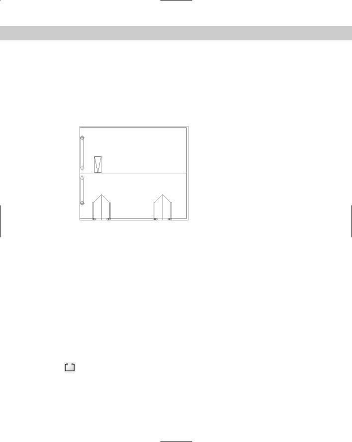
1.Open ab10-h.dwg from your CD-ROM.
2.Save the file as ab10-09.dwg in your AutoCAD Bible folder. This is a site plan, as shown in Figure 10-27. Turn on OSNAP and set running object snaps for endpoint and intersection.
Chapter 10 Editing Your Drawing: Advanced Tools |
221 |
3.Choose Break from the Modify toolbar. At the Select object: prompt, pick the line at 1. At the Specify second break point or [First point]: prompt, pick
2. This action shortens the line.
4.Repeat the BREAK command. At the Select object: prompt, pick the circle (it’s a maple tree) anywhere along its circumference. At the Specify second break point or [First point]: prompt, right-click and choose First point. At the Specify first break point: prompt, pick the intersection at 3. At the Specify second break point: prompt, pick the intersection at 4 to break the circle.
Note |
AutoCAD and AutoCAD LT break circles counterclockwise. If you had picked 4, and then 3, |
|
only the smaller arc would have remained. |
5.Let’s say that you decide this is a mistake. Choose Join from the Modify toolbar. At the Select source object: prompt, select the circle (tree) that you just broke
into an arc. At the Select arcs to join to source or [cLose]: prompt, right-click and choose cLose. The arc becomes a full circle again.
6.To break the line at 5, follow these prompts:
If you’re using AutoCAD: Turn on Object Snap Tracking by clicking OTRACK on the status bar. Start the BREAK command again. Follow the prompts:
Select object: Pick the line at 5.
Specify second break point or [First point]: Right-click and choose First point.
Specify first break point: Move the cursor to 6 to acquire it as a tracking point. Then move the cursor to the right onto the line you are breaking. When you see the Endpoint: Intersection tooltip, click. (You have no visual confirmation yet that you picked the right point.)
Specify second break point: Move the cursor to 7 to acquire it as a tracking point. Then move the cursor onto the line you are breaking. At the Endpoint: 4'-2 3/4"<0.0000 tooltip, click.
If you’re using AutoCAD LT: Start the BREAK command again. Follow the prompts:
Select object: Pick the line at 5.
Specify second break point or [First point]: Right-click and choose First point.
Specify first break point: Shift+right-click and choose Tracking from the Object Snap shortcut menu.
tracking First tracking point: Pick the endpoint at 6. Next point (Press ENTER to end tracking): Press Shift+A to
temporarily override OSNAP and move the cursor to the right onto the
line you are breaking. Click.
Next point (Press ENTER to end tracking):
Specify second break point: _ Shift+right-click and choose Tracking from the Object Snap shortcut menu.
tracking First tracking point: Pick the endpoint at 7. Next point (Press ENTER to end tracking): Press Shift+A to
temporarily override OSNAP and move the cursor to the right onto the
line you are breaking. Click.
Next point (Press ENTER to end tracking):
222 Part II Drawing in Two Dimensions
3
4 7 5
1
6
2
 8
8
 9
9
Figure 10-27: A site plan.
7.Start the JOIN command. At the Select source object: prompt, select the line at 8. At the Select lines to join to source: prompt, select the line at 9. Press Enter to end selection and join the lines into one.
8.Save your drawing. It should look like Figure 10-28.
Figure 10-28: The edited site plan.
Chapter 10 Editing Your Drawing: Advanced Tools |
223 |
On the
CD-ROM
For AutoCAD only: Two AutoLISP programs on the CD-ROM can help you with breaking and unbreaking objects. Pend puts a break line at the end of a pipe. See \Software\ Chap10\Pend. Br draws a line with a break symbol. See \Software\Chap10\Br.
The Express Tools contain a command, BREAKLINE, to create a break symbol. Choose Express Draw Break-Line Symbol. Another Express Tools command, OVERKILL (available on the command line), deletes objects that are on top of other objects. For information about installing Express Tools, see Appendix A.
Creating chamfered corners
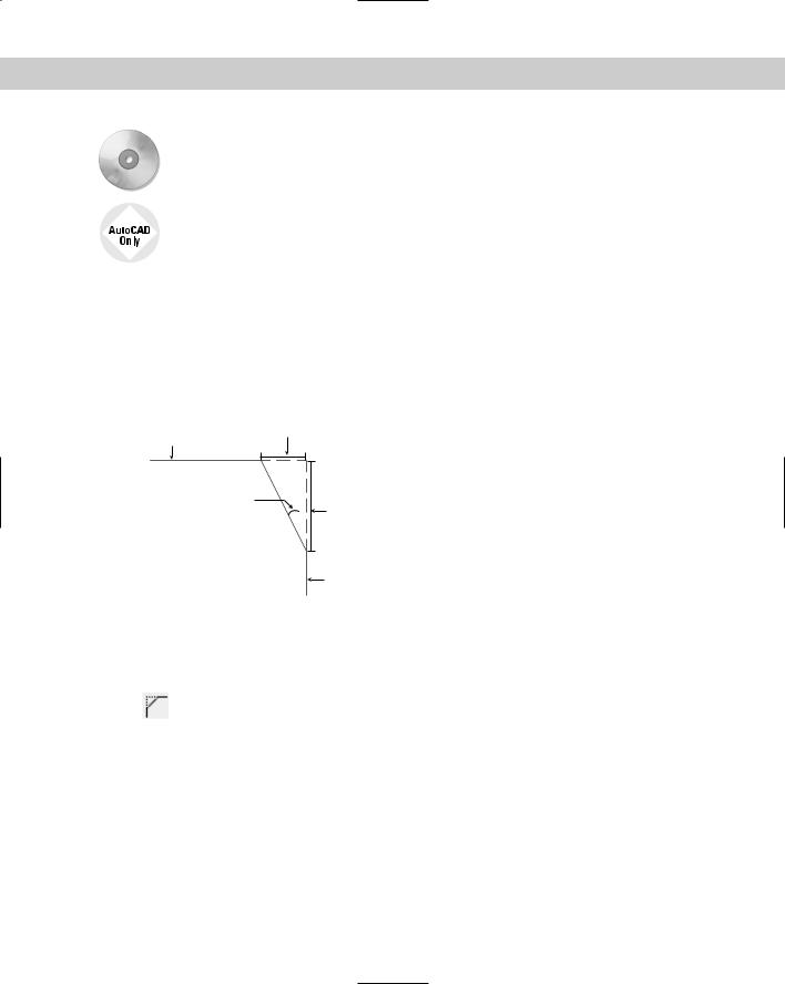
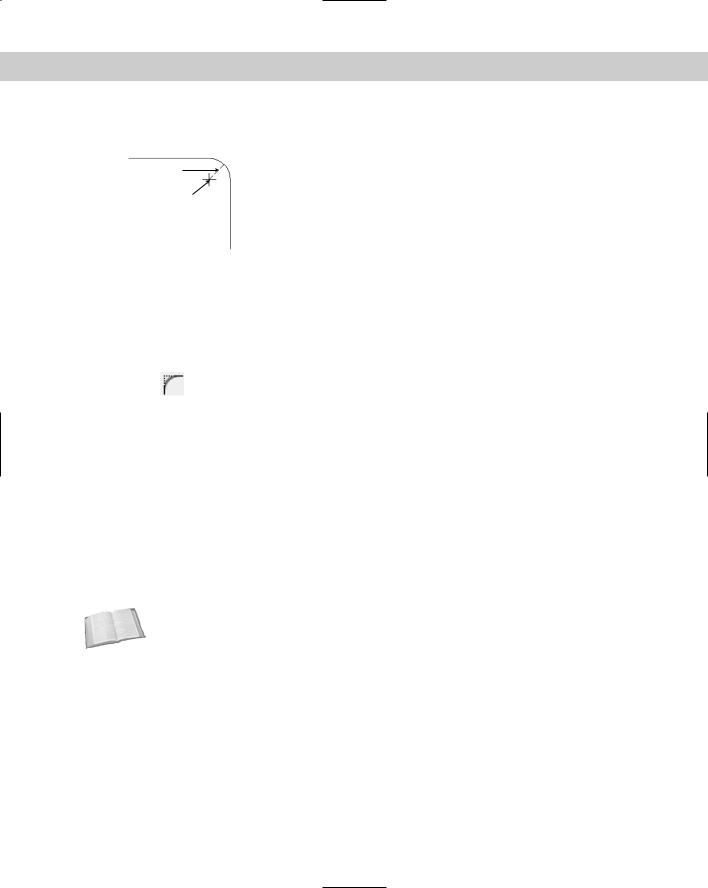
The CHAMFER command creates corners from two nonparallel lines. You can also chamfer xlines, rays, and polylines. You can simply extend the lines to meet at an intersection (a square corner), or create a beveled edge. If you create a beveled edge, you define the edge by either two distances or one distance and an angle relative to the first line that you’re chamfering. Figure 10-29 shows the elements of a chamfered corner.
Second chamfer distance
Second line
Chamfer angle |
First chamfer |
|
|
|
distance |
First line
Figure 10-29: A chamfered corner.
Chamfering is a two-step process. First you define how you want to chamfer the corner, specifying either two distances from the corner or a distance and an angle. Then you select the two lines that you want to chamfer.
To chamfer, choose Chamfer from the Modify toolbar. You cannot select objects before the CHAMFER command. The command responds with the (TRIM mode) Current chamfer
Dist1 = 0.0000, Dist2 = 0.0000 Select first line or [Undo/Polyline/Distance/ Angle/Trim/mEthod/Multiple]: prompt. The command starts by listing the current settings. (The CHAMFER command remembers the last-used chamfer data.) You can define two distances from a corner or one distance and an angle:
To define two distances from the corner, right-click and choose Distance. At the
Specify first chamfer distance <0.0000>: prompt, type the first chamfer distance or press Enter to accept the default (which is the last distance that you defined). At the
Specify second chamfer distance <0.0000>: prompt, type the second distance. The default for this is always the first chamfer distance because equal chamfer distances are so common.
224 Part II Drawing in Two Dimensions
To define a distance (from the corner) and an angle, right-click and choose Angle. At the Specify chamfer length on the first line <1.0000>: prompt, enter a distance. This is the same as the first chamfer distance. At the Specify chamfer angle from the first line <0>: prompt, type the angle between the first line and the chamfer line.
Now that you have specified the settings that you want, you’re ready to chamfer. Your distances or distance and angle are displayed as you just specified them. The command repeats the Select first line or [Undo/Polyline/Distance/Angle/Trim/mEthod/Multiple]: prompt. Select the first line. If you aren’t creating a chamfer with equal distances, the order in which you select the lines is important. The command trims the first line selected by the first distance, and the second line selected based on either the second distance or the angle. At the Select second line: prompt, select the second line to chamfer the lines.
If the lines already intersect, the command trims them to create a corner. The pick points on intersecting lines should be on the part of the lines that you want to keep, not on the part of the lines that you want to trim off.
New
Feature
Cross-
Reference
To quickly create a square corner if you have non-zero settings, press Shift as you select the second line. Of course, you can still set each distance to zero.
Choose the Polyline option to chamfer an entire polyline at once. Chapter 16 covers polylines, and Chapter 24 discusses chamfering 3D models.
By default, CHAMFER trims the original lines that it chamfers. If you want to keep the full original lines when you add the chamfer line, choose the Trim option and choose No Trim. Use the Multiple option to continue the prompts and chamfer several corners in one command. The new Undo option lets you undo your last chamfer and try again.
On the |
The drawing used in the following exercise on chamfering lines, ab10-i.dwg, is in the |
CD-ROM |
Drawings folder on the CD-ROM. |
STEPS: Chamfering Lines
1.Open ab10-i.dwg from your CD-ROM.
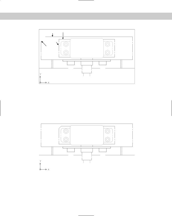
2.Save the file as ab10-10.dwg in your AutoCAD Bible folder. This drawing is a very small section of a “porcupine” mixer, as shown in Figure 10-30.
3.Choose Chamfer from the Modify toolbar. CHAMFER states the current mode and
distances. At the Select first line or [Undo/Polyline/Distance/Angle/ Trim/mEthod/Multiple]: prompt, pick 1 in Figure 10-30. At the Select second line: prompt, pick 2. (If the current distances are not zero, press Shift as you pick 2.)The command chamfers the two lines to make a corner. (If this doesn’t work, you may have the Trim option set to No Trim. Change the setting to Trim and try again.)
4.Repeat the CHAMFER command. Follow the prompts:
Select first line or [Polyline/Distance/Angle/Trim/Method/mUltiple]:
Right-click and choose Angle.
Specify chamfer length on the first line <1>: 9/16 Specify chamfer angle from the first line <0>: 45
Chapter 10 Editing Your Drawing: Advanced Tools |
225 |
2 3
4
1
Figure 10-30: A mechanical drawing showing a small section of a “porcupine” mixer.
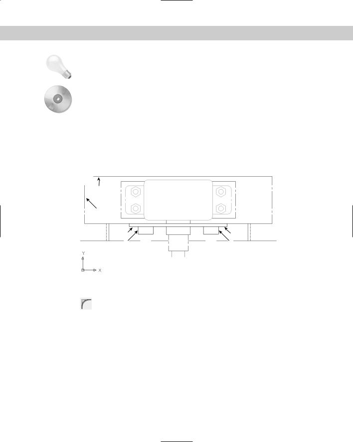
5.At the Select first line or [Undo/Polyline/Distance/Angle/Trim/Method/ mUltiple]: prompt, pick 3 in Figure 10-30. At the Select second line: prompt, pick 4. The command chamfers the two lines, as shown in Figure 10-31.
6.Save your drawing.
Figure 10-31: The edited drawing after using the CHAMFER command.
Creating rounded corners
The FILLET command creates rounded corners, replacing part of two lines with an arc. Fillets are often used in mechanical drawings. In certain cases, you can use FILLET instead of the ARC command to create arcs. As with CHAMFER, you can fillet lines, xlines, rays, and polylines — they can even be parallel. You can also fillet circles, arcs, elliptical arcs, and ellipses.
226 Part II Drawing in Two Dimensions
The FILLET command defines the fillet arc by its radius, as shown in Figure 10-32.
 Fillet arc
Radius
Arc center
Figure 10-32: A fillet consisting of two lines and an arc.
Like chamfering, filleting is a two-step process. First you define the radius of the fillet arc. Then you select the two lines that you want to fillet. You cannot select objects before the FILLET command.
To fillet, follow these steps:
1.Choose Fillet from the Modify toolbar. The command responds with the Current settings: Mode = TRIM, Radius = 0.0000 Select first object or [Undo/
Polyline/Radius/Trim/Multiple]: prompt.
2.Right-click and choose Radius.
3.At the Specify fillet radius <0.0000>: prompt, type the radius you want. The default is either 0.0000 or the last radius that you specified.
4.The command repeats the Select first object or [Undo/Polyline/Radius/Trim/Multiple]: prompt. Select the first object that you want to fillet.
5.At the Select second object or shift-select to apply corner: prompt, select the second object that you want to fillet. This action creates the fillet.
By default, FILLET trims the original lines that it fillets, but the FILLET command recalls the last setting you used. If you want to keep the full original lines when you create a fillet, rightclick and choose the Trim option, and then choose No Trim.
Cross- |
Choose the Polyline option to fillet an entire polyline at once. Chapter 16 covers polylines, |
Reference |
and Chapter 24 discusses filleting 3D models. |
|
Filleting with a zero radius gives the same results as chamfering with distances set to zero. (See the previous section on chamfering.) If your existing settings are non-zero, you can press Shift as you select the second object to create a square corner.
The order in which you select the two objects to be filleted is not important. However, where you pick the objects is quite important. If two objects intersect, the command keeps the objects on the same side of the intersection as your pick point and fillets them. Those parts of the objects on the far side of the intersection are erased.
When you fillet arcs and lines, if more than one fillet is possible, FILLET connects the endpoints closest to your pick points. Filleting circles and lines can produce unexpected results. Sometimes you need to experiment to find the proper pick points.
Chapter 10 Editing Your Drawing: Advanced Tools |
227 |
Tip
On the
CD-ROM
Use the Multiple option to continue the prompts and fillet several corners in one command.
The drawing used in the following exercise on filleting objects, ab10-i.dwg, is in the Drawings folder on the CD-ROM.
STEPS: Filleting Objects
1.Open ab10-i.dwg from your CD-ROM.
2.Save the file as ab10-11.dwg in your AutoCAD Bible folder. This is the same drawing used in the previous exercise. It is shown in Figure 10-33.
2
1
3 |
5 |
4 |
6 |
Figure 10-33: A mechanical drawing showing a small section of a “porcupine” mixer.
3.Choose Fillet from the Modify toolbar. At the Select first object or [Undo/ Polyline/Radius/Trim/Multiple]: prompt, right-click and choose Radius. At
the Specify fillet radius <1/2>: prompt, type 5/8 .
4.At the Select first object or [Undo/Polyline/Radius/Trim/Multiple]: prompt, pick the line at 1 in Figure 10-33. At the Select second object or shift-select to apply corner: prompt, pick the line at 2 to fillet the two lines.
5.Repeat the FILLET command. At the Select first object or [Undo/Polyline/
Radius/Trim/ Multiple]: prompt, right-click and choose Radius. At the Enter fillet radius <5/8>: prompt, type 1/4 .
6.At the Select first object or [Undo/Polyline/Radius/Trim/Multiple]: prompt, right-click and choose mUltiple. Pick the line at 3 in Figure 10-33. At the Select second object or shift-select to apply corner: prompt, pick the line at 4 to fillet the two lines. The prompts continue. This time pick at 5 and 6.
7.If you want, you can connect the two loose lines that the fillets created and create some more fillets in the drawing.