

156 Part II Drawing in Two Dimensions
Figure 8-14: The three tiled viewports now display three different views.
11.Choose 3 view O Ring and click OK to restore the viewport configuration, including the views in each viewport.
12.Save your drawing.
Using Snap Rotation
Not all 2D drawings are vertical and horizontal. In some drawings, significant portions of your objects are drawn at nonorthogonal angles. One example is an auxiliary view to show the “true size” of an inclined surface. Sometimes it helps to rotate the crosshairs to match the major angles of the drawing.
Consider Figure 8-15. A great deal of this drawing is at an angle. You could handle this in four ways:
Draw as normal, specifying the necessary angles.
Rotate the snap, which also rotates the grid and crosshairs.
Create a new UCS (User Coordinate System). (Creating a new UCS is covered later in this chapter.)
Draw the entire model vertically and rotate it afterward.
If you need to draw several objects at a certain angle, such as 45 degrees, you can rotate the snap to that angle. The grid and crosshairs rotate to follow suit. This technique works best when the decimal point accuracy required lets you draw using snap points. You can also use this technique to guide the cursor at an appropriate angle for direct distance entry, although polar tracking is another way to accomplish the same task.
Chapter 8 Viewing Your Drawing 157
To change the snap rotation angle, choose Tools Drafting Settings (or right-click SNAP on the status bar and choose Settings) to open the Drafting Settings dialog box. In the Snap section of the Snap and Grid tab, type an angle in the Angle text box.
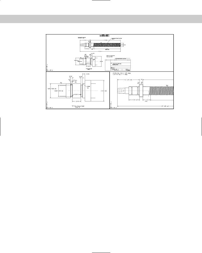
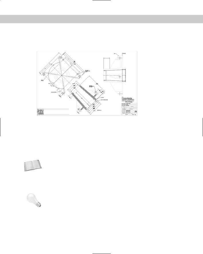
Figure 8-15: In 2D drawings such as this, you should consider various options, such as rotating the snap or creating a new UCS.
Thanks to Robert Mack of The Dexter Company, Fairfield, Iowa, for this drawing.
Note that you can also set an X base and a Y base. This simply ensures that the grid goes through a point of your choice, which is very important if you’re using Snap mode to draw. If you’re just starting to draw an object, use the 0,0 base and draw to the existing snap points. However, if you have an existing object and need to add to it, changing the base can be very helpful. Setting X and Y bases does not change the coordinates, which are tied to the UCS. (The UCS is discussed in the next section.)
Cross- |
|
You can use the ID command to get the coordinates of a point. Then use these coordinates |
Reference |
as the X and Y bases. Chapter 12 covers the ID command. |
|
|
|
|
|
Click OK to return to your drawing. Make sure that the grid is on. The crosshairs and grid now |
|
|
reflect the new snap angle. Figure 8-16 shows the same drawing with a snap angle of 45 degrees. |
|
|
Notice how the crosshairs now match the angle of the drawing. The crosshairs have been set to |
|
|
100 percent of screen size, which is useful when rotating the snap angle. (To reset the crosshairs |
|
|
size, choose Tools Options and use the Crosshair Size section of the Display tab.) |
|
Tip |
|
The grid does not have to be on, but it helps you get your bearings when working with an |
|
|
unusual snap angle. |
You can create a new UCS (User Coordinate System) rather than rotate the snap angle. The results are similar, except that when you create a UCS, you also affect the X,Y coordinates. The UCS is much more flexible when you start drawing in three dimensions.
158 Part II Drawing in Two Dimensions
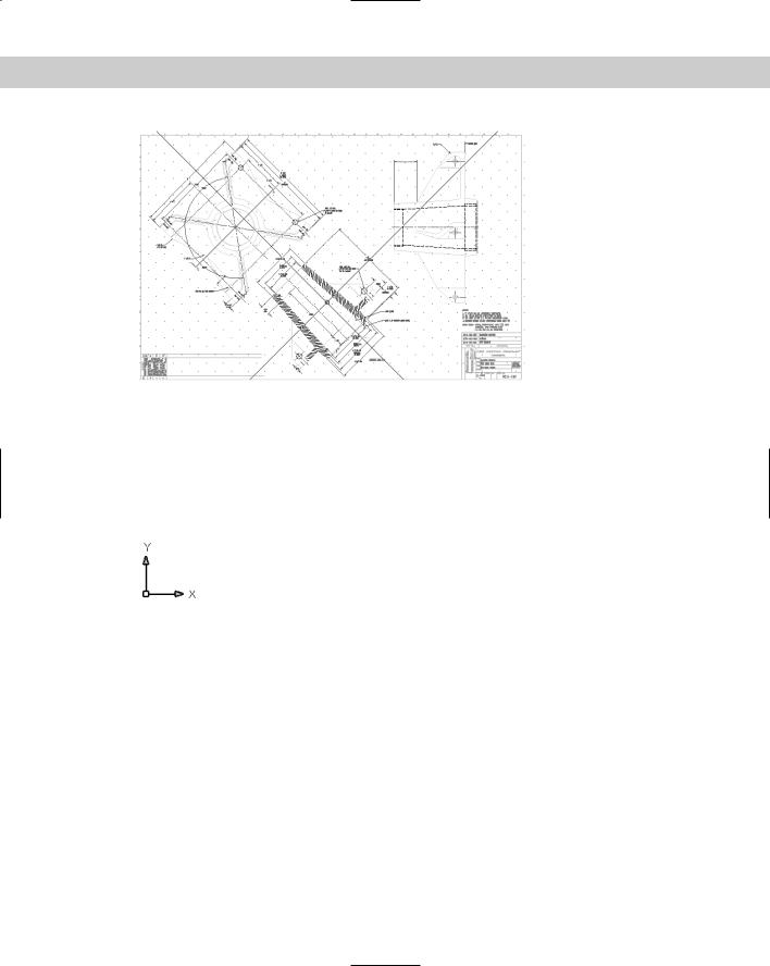
Figure 8-16: The snap angle in this drawing has been changed to 45 degrees. Note that the grid follows the snap.
Understanding User Coordinate Systems
By default, a drawing is set up by using a World Coordinate System. This sets the origin of the X,Y points at 0,0 and the angles using the familiar East (right-facing) equals 0 degrees system. Figure 8-17 shows the UCS icon in its default display.
Figure 8-17: The UCS icon in its default display.
You can easily create your own UCS and even save it for future use in the drawing. Creating a UCS is essential for 3D drawing but often useful for 2D drawing as well.
To define a UCS in a 2D drawing, you indicate the angle of the X and Y axes and an origin point. The origin point then becomes the new 0,0 coordinate. You have several options for specifying the UCS.
Understanding UCS options
Understanding the UCS options will help you create a new UCS more easily, based on the information that you have available. To create a UCS, choose Tools New UCS. A submenu opens, offering the options listed in Table 8-2.
Choose Tools Move UCS to leave the orientation of the X and Y axes the same but move the origin. This option is similar to the Origin option. You can specify a new origin or, for a 3D drawing, move the origin along the Z axis by a positive or negative number of units (called the Z depth).

Chapter 8 Viewing Your Drawing 159
Cross- |
Choose Tools Orthographic UCS to open a submenu with several preset views. These |
Reference |
views are used only in 3D drawings. See Chapter 21 for details on 3D coordinates. |
|
|
Table 8-2: UCS Options |
|
|
Option |
Meaning |
|
|
World |
Specifies the default UCS, with the X axis horizontal, the Y axis vertical, and the origin at |
|
the initial 0,0 location. |
Object |
Enables you to align the UCS with an object. In general, this option uses the most |
|
obvious object snap as the origin and aligns the X axis with the object. For example, |
|
when you choose a line, the endpoint nearest your pick point becomes the origin and |
|
the X axis aligns with the angle of the line. When you choose a circle, the X axis points |
|
toward the point that you pick on the circumference. |
Face |
Aligns the UCS with the face of a 3D solid. |
View |
Aligns the X and Y axes with the current view. Used in 3D drawing. This option arbitrarily |
|
sets the origin. |
Origin |
Specifies a new 0,0 point of your choice, relative to the current origin. |
Z Axis Vector |
Specifies which way the Z axis points. This option is not used in 2D drawing. |
3 Point |
Enables you to specify three points. The first point is the origin, the second point |
|
indicates the positive direction of the X axis, and the third point indicates the positive |
|
direction of the Y axis. |
X |
Keeps the current origin and rotates the Y and Z axes around the current X axis. You specify |
|
the angle. This is used in 3D drawing. |
Y |
Keeps the current origin and rotates the X and Z axes around the current Y axis. You |
|
specify the angle. This is used in 3D drawing. |
Z |
Keeps the current origin and rotates the X and Y axes around the current Z axis. You specify |
|
the angle. This option can be used in 2D drawing. |
Apply |
Applies the current UCS to a specified viewport. |
|
|
Saving and restoring a custom UCS
After you create a UCS, you can save it so that you can easily switch back and forth between the World Coordinate System and your UCS. To save a UCS, follow these steps:
1.Specify the UCS as described in the previous section.
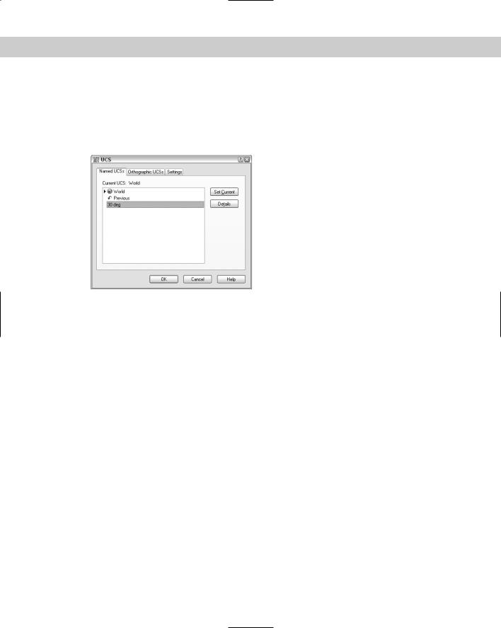
2.Choose Tools Named UCS to open the UCS dialog box with the Named UCSs tab on top, as shown in Figure 8-18. If your current UCS is not named, it is listed as Unnamed and highlighted. Previously named UCSs are also listed. You can also use this dialog box to return to the previous UCS or the World Coordinate System (WCS).
3.Click Unnamed. Type a name for the UCS and press Enter. The name can be up to 255 characters and can include spaces.
4.Click OK.
160 Part II Drawing in Two Dimensions
To restore a saved UCS, choose Tools Named UCS. Choose the UCS that you want to use and click Set Current. Then click OK. You can use the same dialog box to return to the previous UCS that you used. You can also choose UCS Previous from the UCS toolbar. Using this button, you can quickly switch back and forth between two UCSs. To delete a saved UCS, select it in the UCS dialog box and press the Del key. You can also select a UCS, right-click, and choose one of the options from the shortcut menu.
Figure 8-18: Use the UCS dialog box to save and restore a UCS.
Controlling the UCS icon
When you start a new drawing, the UCS icon is at the bottom-left of your drawing at 0,0. By default, the icon remains at 0,0 even if you pan around the drawing. The icon may, therefore, end up in the middle of your drawing. If 0,0 is not displayed, then the icon reverts to the bottom-left of your drawing.
You can turn off the UCS icon completely. If you aren’t working with customized UCSs, you often have no reason to see the UCS in a 2D drawing. If you want the UCS icon on, you can also display it only at the bottom-left of your drawing. This keeps the icon out of the way so that it does not obstruct your drawing.
If you create a new UCS, keeping the UCS icon at the 0,0 point (the origin) of your new UCS helps you to get your bearings. A plus sign appears in the icon to indicate the origin. However, if the origin is out of the current display or so close to the edge that the icon won’t fit, the UCS icon appears at the lower-left corner of your drawing anyway.
To control the UCS icon, choose View Display UCS Icon. (Don’t confuse this with Tools New UCS, which creates a custom UCS.) A submenu opens with the following items:
On: Toggles the display of the UCS icon on and off.
Origin: Toggles the placement of the UCS icon at the origin on and off.
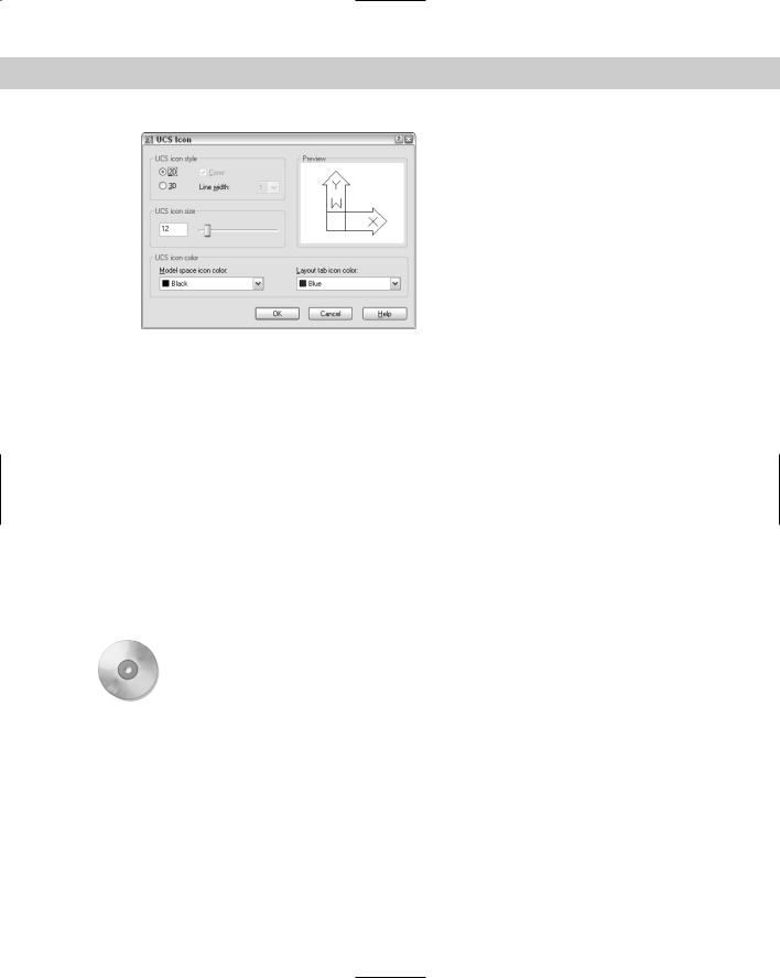
You can customize the look of the UCS icon. To do this, choose View Display UCS Icon Properties to open the UCS Icon dialog box, shown in Figure 8-19. As you make changes, you can see the result in the preview box.
Chapter 8 Viewing Your Drawing 161
Figure 8-19: Use the UCS Icon dialog box to customize the look of the UCS icon.
Choose between 2D and 3D styles. The 3D style shows the Z axis, but you won’t see it when you’re looking at your model from the top (called Plan view). If you choose the 3D style, you can check the Cone box to display a cone effect for the arrows of the X and Y axes. Either way, the Z axis has no arrow, which enables you to distinguish it from the X and Y axes. You can also choose a line width from 1 to 3, 1 being the default.
You can change the size of the icon. Just drag the slider up and down to get the result you like. Finally, you can change the color of the icon, both in model space and in paper space layouts. Click OK to close the dialog box.
Using a custom UCS
Although it seems confusing at first, after you try creating your own UCS, it’s easier to understand how the process works.
In this exercise, you practice drawing with a custom UCS to create the basic framework for the drawing shown previously in Figures 8-15 and 8-16, a bearing housing for a commercial dryer.
On the |
The drawing used in the following exercise on drawing with a custom UCS, ab08-d.dwg, is |
CD-ROM |
in the Drawings folder on the CD-ROM. |
STEPS: Drawing with a Custom UCS
1.Open ab08-d.dwg from the CD-ROM. This exercise assumes that you have Dynamic Input on, with the default relative coordinates setting.
2.Save the file as ab08-03.dwg in your AutoCAD Bible folder. ORTHO should be on. If necessary, turn on OSNAP. Set a running object snap for endpoints only.
3.Choose Tools New UCS Z. Because no objects exist in the drawing, you cannot easily use the 3 Point or Object options that might otherwise be useful.
4.At the Specify rotation angle about Z axis <90>: prompt, type 45 . The UCS icon and crosshairs are displayed at a 45-degree angle.
162 Part II Drawing in Two Dimensions
5.Choose Line from the Draw toolbar. At the prompt, pick a point in the middle of your screen. At the Specify next point or [Undo]: prompt, type 1.25<90 . End the LINE command.
6.Choose Rectangle from the Draw toolbar. Choose the From object snap. At the Base
point: prompt, use the Endpoint object snap to pick the endpoint of the line that you just drew. At the <Offset>: prompt, type @.875,0 . At the Specify other corner point or [Dimensions]: prompt, type -5.5,1.5 . The command creates the rectangle at the proper angle.
7.Start the LINE command. Follow the prompts:
Specify first point: Choose the From object snap.
Base point: Use the Endpoint object snap to pick point 1 in Figure 8-20.
<Offset>: Type @-.875,0 .
Specify next point or [Undo]: Move the cursor in the 90° direction (which looks like the 135° direction because of the rotated UCS).
.625
Specify next point or [Undo]: Move the cursor in the 180° direction.
3.75
Specify next point or [Close/Undo]: Move the cursor in the 270° direction. .625
Specify next point or [Close/Undo]:
8.Start the LINE command again.
If you have AutoCAD, turn on OTRACK on the status bar and follow the prompts:
Specify first point: Pass the cursor over 2 and then over 3 to acquire these points. Move the cursor to 4 at the intersection of the two temporary tracking lines and click.
Specify next point or [Undo]: Move the cursor in the 270° direction relative to the UCS. 1.25 .
Specify next point or [Undo]:
If you have AutoCAD LT: Follow the prompts:
Specify first point: .x of Pick 2
(need YZ): Pick 3
Specify next point or [Undo]: Move the cursor in the 270° direction.
1.25
Specify next point or [Undo]:
9.Because you would normally continue working on this drawing, you should save the UCS. Choose Tools Named UCS. In the UCS dialog box, click Unnamed. Type Rotated 45 and press Enter.
10.Still in the dialog box, choose World, click Set Current, and click OK to return to your drawing. The UCS icon and crosshairs return to their familiar angle.