


104 Part I AutoCAD and AutoCAD LT Basics
5.The actual drawing space (minus the margins the printer requires) on a C-size sheet is about 21"×16". The height of the drawing at this scale is adequate, but the width is 7⁄8" too long. Therefore, the best option is to simply make the drawing 7⁄8" narrower because the drawing has some extra room. This lets you fit the drawing on a C-size sheet.
6.To calculate the scale factor of a 1⁄8"=1' scale, multiply 1' by 8 to get 8' and convert it to inches, which is 96 (8×12).
Rearranging the views, dimensions, and text on a drawing to fit a standard scale factor and sheet size is a typical task. There is no actual setup step for setting the drawing scale, but you use it when you insert text or dimensions and when you plot the drawing.
Creating a Title Block
A title block is a rectangle that includes spaces for the drawing title, company name, drafter name, and so on. It generally comes with a border that bounds your drawing. Many drawings require title blocks. You can insert an existing title block in two ways:
When creating a new drawing, choose File New to open the Select Template dialog box. Choose one of the templates that include a title block. For example, ANSI A –Named Plot Styles.dwt includes a title block and border that fit on an A-size sheet. The title block and border appear on a layout tab. (Chapter 17 covers layouts.)
After you open a drawing, you can insert a drawing of a title block into it. Choose Insert Block. (Chapter 18 covers blocks.) In the Insert dialog box, type the name of the drawing or block, or click Browse to find it. Most of the templates have a corresponding drawing that you can insert. To insert the file or block at 0,0 with no scaling or rotation, uncheck all of the Specify On-Screen check boxes. Check Explode if you expect to edit the inserted title block after it’s in your drawing. Click OK.
To find the location of the templates and their corresponding drawings, choose Tools Options and click the Files tab. Double-click Template Settings and then double-click Drawing Template File Location. You see the path to the location displayed. (The path is very long!) This folder may be hidden in Windows Explorer. For instructions on displaying hidden folders, go to Windows Help and type hidden folders in the search box.
Cross- |
As explained in Chapter 2, you can create your own title block, make a template from it, and |
Reference |
then start a drawing based on that template. |
|
Specifying Common Setup Options
A few other items are generally set up in advance and are included in a template. Other chapters of this book cover the following:
Layers (covered in Chapter 11) enable you to organize your drawing into meaningful groups. In an architectural drawing, for example, you might create a layer for walls, another for doors, and one for electrical fixtures.

Chapter 5 Setting Up a Drawing 105
Text styles (covered in Chapter 13) enable you to format the font and other text characteristics.
Table styles (covered in Chapter 13) format tables.
Dimension styles (covered in Chapter 15) format the dimensions that measure your objects.
If you know you’ll be using snap, grid, and Ortho modes a lot in certain drawings, and you know the suitable settings for snap and grid, you can set these and save them in a template because these settings are saved with the drawing. In other cases, you might want to leave them off and turn them on only when you need them.
Many settings, such as running object snaps, the type of snap (grid or polar), and the polar distance when you’re using PolarSnap, are saved in the Windows registry, not in your drawing. As a result, when you open AutoCAD or AutoCAD LT, they’re automatically set to the same setting that you had when you last closed the program, regardless of the setting in the drawing. Therefore, you cannot save these settings in a template.
In this exercise, you practice specifying the drafting settings and creating a template.
System Variables
When you change settings in AutoCAD or AutoCAD LT, such as the unit type, angle type, drawing limits, blip marks, snap mode (on or off), grid mode, or ortho mode, you’re actually changing system variables. These are simply settings that are stored in each drawing or in the Windows registry (which stores settings that apply to all drawings). Usually, you don’t need to pay any direct attention to them, but they’re the nuts and bolts behind the dialog boxes that you use to change the settings. When you start customizing AutoCAD, you need to learn about them because programming code and script files (macros) cannot access dialog boxes. Also, a few system variables are accessible only by typing them directly on the command line. Appendix B provides more information on system variables. Throughout this book, I occasionally mention system variables when using them directly is useful. Some system variables store information about a drawing or the drawing environment, such as the drawing name and path. These are read-only, meaning that you cannot change them. They exist to provide information and are often used in AutoLISP programs. (AutoLISP works in AutoCAD only.)
Information about each system variable, where it is stored, its default, and whether it is read-only is in the Help system. Choose Help Help and double-click Command Reference on the Contents tab. Then double-click System Variables. In the Options dialog box (Tools Options), system variables that are stored in a drawing have a blue crosshairs icon next to them.
You can type system variables on the command line, just like regular commands. The Express Tools (AutoCAD only) contain an editor (choose Express Tools System Variable Editor) that enables you to edit system variable values in a dialog box; it also provides helpful supporting information.
106 Part I AutoCAD and AutoCAD LT Basics
On the |
The drawing used in the following exercise on setting drawing aids and creating a template, |
CD-ROM |
ab05-02.dwg, is in the Results folder on the CD-ROM. |
STEPS: Setting Drawing Aids and Creating a Template
1.If you did the exercise on drawing limits, use that drawing or open ab05-02.dwg from the Results folder of the CD-ROM.
2.Save the drawing as ab05-03.dwg in your AutoCAD Bible folder.
3.Choose Tools Drafting Settings.
4.On the Snap and Grid tab, the snap spacing is set to 1⁄2". In the Grid section, change the X spacing to 1". Make sure the Snap Type is set to Grid Snap and Rectangular Snap. Click OK.
5.Click SNAP and GRID on the status bar to turn them on. Make sure OSNAP is turned off.
6.Choose Format Units. Change the Angle Type back to decimal degrees. Click OK.
7.Using the coordinate display as your guide, start the LINE command and draw line segments from 2.5, 1.5 to .5<270 to 11<0 to .5<90. End the LINE command.
8.Restart the LINE command. Again use the coordinate display to draw line segments from 2,2 to .5<270 to 12<0 to .5<90. End the LINE command.
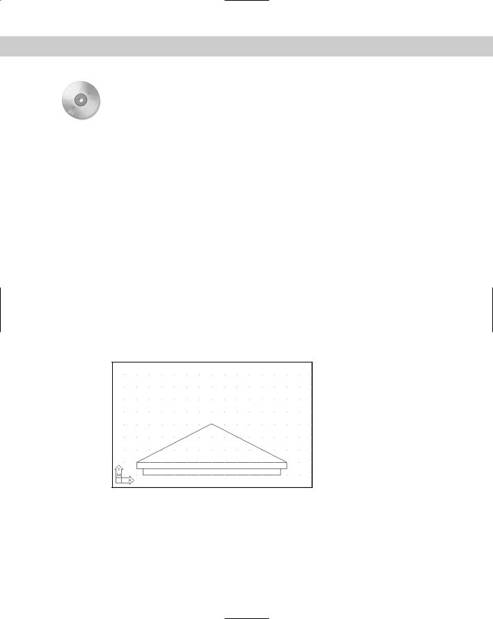
9.Save your drawing. It should look like Figure 5-5. Notice how the grid and snap settings facilitate the drawing process.
The architectural units create a different drawing experience than decimal units would. Setting up a drawing creates a drawing environment suited to your work needs.
Figure 5-5: The final architectural drawing.
10.Choose File Save As. In the Save Drawing As dialog box, click the Files of Type dropdown list box and choose AutoCAD Drawing Template or AutoCAD LT Drawing Template (*.dwt). Notice that you’re automatically in the Template folder.
11.In the File Name text box, change the name to archroof.dwt. Click Save.
12.In the Template Description dialog box, type Arch units, 16,10 limits, snap & grid and click OK.

Chapter 5 Setting Up a Drawing 107
13.Choose File New. Choose the archroof template and click Open. A new drawing is created based on the template.
14.Move the cursor around and look at the coordinate display to confirm that the grid is set to 1", although the snap is set to 1⁄2".
Do not save this new drawing.
Customizing with the MVSETUP Command
The MVSETUP command is used in two different ways: to set up a drawing and to create viewports for paper space layouts. This command does not exist in AutoCAD LT.
Cross- |
Paper space layouts are a way of laying out your drawing in preparation for printing or plotting. |
Reference |
Chapter 17, which covers laying out a drawing as well as plotting, discusses paper space layouts. |
|
MVSETUP provides a command-line routine to walk you through some of the basic setup functions discussed in this chapter. You can use MVSETUP when you start to customize AutoCAD to set up a drawing from a script file or AutoLISP program (topics covered in Parts VI and VII of this book). To use MVSETUP, type mvsetup on the command line. AutoCAD responds with the following prompt:
Enable paper space? [No/Yes] <Y>:
Type n to use MVSETUP without entering paper space.
The next prompt lets you enter the units type:
Enter units type [Scientific/Decimal/Engineering/Architectural/Metric]:
Choose the option you want. Then AutoCAD displays a list of scale factors appropriate to the units option you chose. At the Enter the scale factor: prompt, type in a numeric scale factor.
Finally, AutoCAD prompts you to set the drawing limits with the following two prompts:
Enter the paper width:
Enter the paper height:
After each prompt, enter a number based on the size of the paper on which you plan to plot. AutoCAD draws a rectangle of the size that you indicated for the drawing limits.
Using the Setup Wizards
There are two wizards to help you set up a drawing. You need to activate the Startup dialog box to find them:
1.Choose Tools Options and click the System tab. In the General Options section, choose Show Startup Dialog Box from the Startup drop-down list. Click OK.
2.Choose File New. You see the Startup dialog box.
3.Click the Use a Wizard button. Choose Quick Setup for fewer options or Advanced Setup for more options.
4.Click OK and follow the prompts of the wizard.