

- •Contents
- •Contents at a Glance
- •Acknowledgments
- •Preface
- •Is This Book for You?
- •How This Book Is Organized
- •How to Use This Book
- •Doing the Exercises
- •Conventions Used in This Book
- •What the Icons Mean
- •About the CD-ROM
- •Other Information
- •Contacting the Author
- •Foreword
- •Credits
- •About the Author
- •Summary
- •AutoCAD’s Advantages
- •Comparing AutoCAD and AutoCAD LT
- •Starting AutoCAD and AutoCAD LT
- •Creating a New Drawing
- •Using the AutoCAD and AutoCAD LT Interface
- •Creating a New Folder
- •Using the Interface
- •Saving a Drawing
- •Closing a Drawing and Exiting from AutoCAD and AutoCAD LT
- •Summary
- •Creating a New Drawing from a Template
- •Working with Templates
- •Opening a Drawing with Default Settings
- •Opening an Existing Drawing
- •Using an Existing Drawing as a Prototype
- •Saving a Drawing Under a New Name
- •Summary
- •The Command Line and Dynamic Input
- •Command Techniques
- •Of Mice and Pucks
- •Getting Help
- •Summary
- •Typing Coordinates
- •Displaying Coordinates
- •Picking Coordinates on the Screen
- •Overriding Coordinate Settings
- •Locating Points
- •Summary
- •Choosing Unit Types
- •Drawing Limits
- •Understanding Scales
- •Creating a Title Block
- •Specifying Common Setup Options
- •Customizing with the MVSETUP Command
- •Using the Setup Wizards
- •Summary
- •Using the LINE Command
- •Drawing Rectangles
- •Drawing Polygons
- •Creating Construction Lines
- •Creating Rays
- •Summary
- •Drawing Circles
- •Drawing Arcs
- •Creating Ellipses and Elliptical Arcs
- •Making Donuts
- •Placing Points
- •Summary
- •Panning
- •Using the ZOOM Command
- •Using Aerial View
- •Saving Named Views
- •Working with Tiled Viewports
- •Using Snap Rotation
- •Understanding User Coordinate Systems
- •Creating Isometric Drawings
- •Summary
- •Editing a Drawing
- •Selecting Objects
- •Summary
- •Copying and Moving Objects
- •Resizing Commands
- •Using Construction Commands
- •Creating a Revision Cloud
- •Hiding Objects with a Wipeout
- •Double-Clicking to Edit Objects
- •Grips
- •Editing with the Properties Palette
- •Selection Filters
- •Groups
- •Summary
- •Working with Layers
- •Changing Object Color, Linetype, and Lineweight
- •Working with Linetype Scales
- •Importing Layers and Linetypes from Other Drawings
- •Matching Properties
- •Summary
- •Drawing-Level Information
- •Object-Level Information
- •Measurement Commands
- •AutoCAD’s Calculator
- •Summary
- •Creating Single-Line Text
- •Understanding Text Styles
- •Creating Multiline Text
- •Creating Tables
- •Inserting Fields
- •Managing Text
- •Finding Text in Your Drawing
- •Checking Your Spelling
- •Customizing the spelling dictionary
- •Summary
- •Working with Dimensions
- •Drawing Linear Dimensions
- •Drawing Aligned Dimensions
- •Creating Baseline and Continued Dimensions
- •Dimensioning Arcs and Circles
- •Dimensioning Angles
- •Creating Ordinate Dimensions
- •Drawing Leaders
- •Using Quick Dimension
- •Editing Dimensions
- •Summary
- •Understanding Dimension Styles
- •Defining a New Dimension Style
- •Changing Dimension Styles
- •Creating Geometric Tolerances
- •Summary
- •Creating and Editing Polylines
- •Drawing and Editing Splines
- •Creating Regions
- •Creating Boundaries
- •Creating Hatches
- •Creating and Editing Multilines
- •Creating Dlines
- •Using the SKETCH Command
- •Digitizing Drawings with the TABLET Command
- •Summary
- •Preparing a Drawing for Plotting or Printing
- •Creating a Layout in Paper Space
- •Working with Plot Styles
- •Plotting a Drawing
- •Summary
- •Combining Objects into Blocks
- •Inserting Blocks and Files into Drawings
- •Managing Blocks
- •Creating and Using Dynamic Blocks
- •Using Windows Features
- •Working with Attributes
- •Summary
- •Understanding External References
- •Editing an Xref within Your Drawing
- •Controlling Xref Display
- •Managing Xrefs
- •Summary
- •Preparing for Database Connectivity
- •Connecting to Your Database
- •Linking Data to Drawing Objects
- •Creating Labels
- •Querying with the Query Editor
- •Working with Query Files
- •Summary
- •Working with 3D Coordinates
- •Using Elevation and Thickness
- •Working with the User Coordinate System
- •Summary
- •Working with the Standard Viewpoints
- •Using DDVPOINT
- •Working with the Tripod and Compass
- •Displaying a Quick Plan View
- •Shading Your Drawing
- •Using 3D Orbit
- •Using Tiled Viewports
- •Defining a Perspective View
- •Laying Out 3D Drawings
- •Summary
- •Drawing Surfaces with 3DFACE
- •Drawing Surfaces with PFACE
- •Creating Polygon Meshes with 3DMESH
- •Drawing Standard 3D Shapes
- •Drawing a Revolved Surface
- •Drawing an Extruded Surface
- •Drawing Ruled Surfaces
- •Drawing Edge Surfaces
- •Summary
- •Drawing Standard Shapes
- •Creating Extruded Solids
- •Drawing Revolved Solids
- •Creating Complex Solids
- •Sectioning and Slicing Solids
- •Using Editing Commands in 3D
- •Editing Solids
- •Listing Solid Properties
- •Summary
- •Understanding Rendering
- •Creating Lights
- •Creating Scenes
- •Working with Materials
- •Using Backgrounds
- •Doing the Final Render
- •Summary
- •Accessing Drawing Components with the DesignCenter
- •Accessing Drawing Content with Tool Palettes
- •Setting Standards for Drawings
- •Organizing Your Drawings
- •Working with Sheet Sets
- •Maintaining Security
- •Keeping Track of Referenced Files
- •Handling Errors and Crashes
- •Managing Drawings from Prior Releases
- •Summary
- •Importing and Exporting Other File Formats
- •Working with Raster Images
- •Pasting, Linking, and Embedding Objects
- •Summary
- •Sending Drawings
- •Opening Drawings from the Web
- •Creating Object Hyperlinks
- •Publishing Drawings
- •Summary
- •Working with Customizable Files
- •Creating Keyboard Shortcuts for Commands
- •Customizing Toolbars
- •Customizing Tool Palettes
- •Summary
- •Creating Macros with Script Files
- •Creating Slide Shows
- •Creating Slide Libraries
- •Summary
- •Creating Linetypes
- •Creating Hatch Patterns
- •Summary
- •Creating Shapes
- •Creating Fonts
- •Summary
- •Working with the Customization File
- •Customizing a Menu
- •Summary
- •Introducing Visual LISP
- •Getting Help in Visual LISP
- •Working with AutoLISP Expressions
- •Using AutoLISP on the Command Line
- •Creating AutoLISP Files
- •Summary
- •Creating Variables
- •Working with AutoCAD Commands
- •Working with Lists
- •Setting Conditions
- •Managing Drawing Objects
- •Getting Input from the User
- •Putting on the Finishing Touches
- •Summary
- •Understanding Local and Global Variables
- •Working with Visual LISP ActiveX Functions
- •Debugging Code
- •Summary
- •Starting to Work with VBA
- •Writing VBA Code
- •Getting User Input
- •Creating Dialog Boxes
- •Modifying Objects
- •Debugging and Trapping Errors
- •Moving to Advanced Programming
- •Summary
- •A Final Word
- •Installing AutoCAD and AutoCAD LT
- •Configuring and Using Workspaces
- •Configuring AutoCAD
- •Starting AutoCAD Your Way
- •Configuring a Plotter
- •Discovering AutoCAD and AutoCAD LT
- •Accessing Technical Support
- •Autodesk User Groups
- •Internet Resources
- •System Requirements
- •Using the CD-ROM with Microsoft Windows
- •What’s on the CD-ROM
- •Troubleshooting
- •Index
Chapter 34 Understanding AutoLISP and Visual LISP Basics 1043
4.Select the line of the code that reads:
(command “_circle” pt “3”)
5.Choose Comment Block. AutoCAD places three semicolons before the text and shades it. Choose Uncomment Block. AutoCAD returns the code to its previous
state.
6.Choose Check Edit Window on the toolbar. AutoCAD opens the Build Output window and issues the Check done message.
7.Click anywhere in the edit window to activate it. Choose Load Active Edit Window on the toolbar. AutoCAD loads the routine.
8.In the Visual LISP Console window, type (c:circle3) and press Enter. Visual LISP returns you to AutoCAD and starts the program. Pick a point. When you’re done, you’re automatically returned to the Visual LISP window.
9.Click the text editor window and choose Save File. Click the Close button at the top-right corner of the text editor window to close the routine.
10.Click the Close button at the top-right corner of your screen to close Visual LISP.
Getting Help in Visual LISP
Visual LISP offers two ways for you to get help while writing AutoLISP code: context-sensitive help on any term that you select, and the overall Help system.
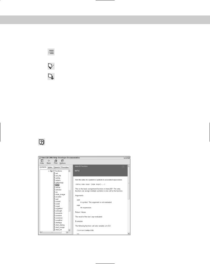
To get help on any AutoLISP function in your code, select the function (either in the edit window or in the Console window) and choose Help on the Visual LISP Tools toolbar.
Figure 34-5 shows the screen that appears when you select setq and choose Help.
Figure 34-5: When you select any AutoLISP function in your code and choose Help, Visual LISP opens the help page for that function.
1044 Part VII Programming AutoCAD
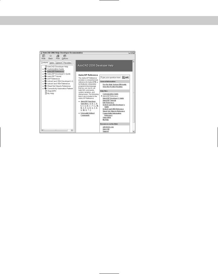
To open the entire Visual LISP and ActiveX Help system, choose Help Visual LISP Help Topics on the Visual LISP menu or Press F1. Visual LISP displays the screen shown in Figure 34-6.
Figure 34-6: The main help page of Visual LISP’s Help system.
All of these help features can be a bit overwhelming, but for AutoLISP and Visual LISP you basically have three choices:
AutoLISP Reference: This guide is equivalent to the Command Reference in AutoCAD’s Help system. Here you’ll find an alphabetical list of all AutoLISP functions.
AutoLISP Developer’s Guide: This guide is equivalent to the AutoCAD User’s Guide. It contains all of the basic topics that you need to know to program in Visual LISP.
AutoLISP Tutorial: This is a tutorial that creates a garden path.
Working with AutoLISP Expressions
As with any programming language, AutoLISP has its own functions and syntax. This section explains how to start writing AutoLISP code. One big advantage to AutoLISP is that you can test your code immediately, unlike the case of compiled languages for which extra steps are required. For compiled languages, every time a code change is made, the code must be recompiled and re-linked before you can see the changes in AutoCAD. For example, this is the case with ObjectARX.
Understanding AutoLISP syntax
In AutoLISP’s syntax, an operator always comes first, followed by a number of operands. An operator can be thought of as a function that does something, and the operands are the elements on which the function operates. Place a space between each component of the statement.

Chapter 34 Understanding AutoLISP and Visual LISP Basics 1045
Another way to describe the syntax of AutoLISP is that, within each set of parentheses, the first item is a function, and what follows are parameters or arguments to that function.
Working with numbers and text
Table 34-1 lists the basic arithmetic functions. You can use these functions on anything that has a value. For example, if you create a variable with a value of 2, you can use that variable with the arithmetic functions.
|
Table 34-1: Basic Arithmetic Functions |
|
|
Function |
Description |
|
|
+ |
Addition |
- |
Subtraction |
* |
Multiplication |
/ |
Division |
Sqrt |
Square root |
|
|
Table 34-1 lists only a few fundamental arithmetic operators (or functions). Many operators are available to the AutoLISP programmer. You can find more operators in the AutoLISP Function Synopsis Appendix of the AutoLISP Developer’s Guide, under Basic Functions Arithmetic Functions.
Some fundamental arithmetic operations can provide a feel for the fundamentals. If you type (+ 2 3) on the AutoCAD command line (being careful to put a blank space after the + and the 2), AutoLISP responds with 5. This syntax of having the operator (the plus sign) come before the operands (2 and 3) is different from that of many languages, but is important to understand in AutoLISP.
To nest expressions, simply add another set of parentheses to enclose the nested expression. For example, when you enter (* 5 (+ 2 3)), AutoCAD responds with 25. The nested expression is evaluated from the innermost parenthesis pair out; first 2 and 3 are added, and then that sum is multiplied by 5.
Working with floating point numbers (numbers with decimal points) is as easy as working with integers. If you type (/ 7.3 5.84) , then AutoLISP responds with 1.25.
Note |
If you’re using a number less than 1, you must include the leading 0, as in (+ 2.5 0.5). |
Working with text is as easy as working with numbers. In AutoLISP, a string is simply some text. Table 34-2 lists some common string functions.

1046 Part VII Programming AutoCAD
|
Table 34-2: Basic String Functions |
|
|
Function |
Description |
|
|
STRCAT |
Concatenates (attaches) strings to one another. |
SUBSTR |
Returns (provides you with) a substring (a portion) of a string. The first |
|
argument is the string, the second is an integer that specifies the position of |
|
the first character that you want, and the third (optional) is the number of |
|
characters that you want. |
STRLEN |
Calculates string length; returns the number of characters, including spaces in |
|
the string. |
|
|
Here are two examples:
(strcat “Today is “ “a good day” “.”) “Today is a good day.”
(substr “Today is a good day.” 12 4) “good”
STRCAT stands for string concatenate and appends one string with another. Any number of strings can come after the STRCAT function. (There are three strings enclosed in quotes in the above STRCAT example.)
SUBSTR stands for substring, and in the above example, it returns the four characters starting at position 12.
Note |
The first character of the string for SUBSTR is number 1. However, other functions that process |
|
elements of a list (such as NTH) count the first element as 0. |
Table 34-3 offers you a few more functions that work with numbers and strings.
|
Table 34-3: AutoLISP Functions for Numbers and Strings |
|
|
Function |
Description |
|
|
ABS |
Returns the absolute value of the argument. (ABS -76) returns 76. |
ASCII |
Returns the ASCII code of a character. (ASCII “B”) returns 66. |
CHR |
Returns the text string for an ASCII code. (CHR 66) returns “B”. (Stands for character.) |
ATOI |
Converts a string to an integer. (ATOI “2.7”) returns 2. (Stands for ASCII to integer.) |
ATOF |
Converts a string to a real number. (ATOF “7.6”) returns 7.6. (Stands for ASCII to float, as in |
|
floating point — that is, a real number.) |
ITOA |
Converts an integer to a text string. (ITOA 76) returns “76”. (Stands for integer to ASCII.) |
RTOS |
Converts a real number to a text string, enclosed in quotes. You can add a mode |
|
(1=scientific, 2=decimal, 3=engineering, 4=architectural, 5=fractional) and a precision. |
|
Otherwise, RTOS uses the current settings. (RTOS 87.3 2 2) returns “87.30”. (RTOS stands for |
|
real to string.) |