

- •Contents
- •Contents at a Glance
- •Acknowledgments
- •Preface
- •Is This Book for You?
- •How This Book Is Organized
- •How to Use This Book
- •Doing the Exercises
- •Conventions Used in This Book
- •What the Icons Mean
- •About the CD-ROM
- •Other Information
- •Contacting the Author
- •Foreword
- •Credits
- •About the Author
- •Summary
- •AutoCAD’s Advantages
- •Comparing AutoCAD and AutoCAD LT
- •Starting AutoCAD and AutoCAD LT
- •Creating a New Drawing
- •Using the AutoCAD and AutoCAD LT Interface
- •Creating a New Folder
- •Using the Interface
- •Saving a Drawing
- •Closing a Drawing and Exiting from AutoCAD and AutoCAD LT
- •Summary
- •Creating a New Drawing from a Template
- •Working with Templates
- •Opening a Drawing with Default Settings
- •Opening an Existing Drawing
- •Using an Existing Drawing as a Prototype
- •Saving a Drawing Under a New Name
- •Summary
- •The Command Line and Dynamic Input
- •Command Techniques
- •Of Mice and Pucks
- •Getting Help
- •Summary
- •Typing Coordinates
- •Displaying Coordinates
- •Picking Coordinates on the Screen
- •Overriding Coordinate Settings
- •Locating Points
- •Summary
- •Choosing Unit Types
- •Drawing Limits
- •Understanding Scales
- •Creating a Title Block
- •Specifying Common Setup Options
- •Customizing with the MVSETUP Command
- •Using the Setup Wizards
- •Summary
- •Using the LINE Command
- •Drawing Rectangles
- •Drawing Polygons
- •Creating Construction Lines
- •Creating Rays
- •Summary
- •Drawing Circles
- •Drawing Arcs
- •Creating Ellipses and Elliptical Arcs
- •Making Donuts
- •Placing Points
- •Summary
- •Panning
- •Using the ZOOM Command
- •Using Aerial View
- •Saving Named Views
- •Working with Tiled Viewports
- •Using Snap Rotation
- •Understanding User Coordinate Systems
- •Creating Isometric Drawings
- •Summary
- •Editing a Drawing
- •Selecting Objects
- •Summary
- •Copying and Moving Objects
- •Resizing Commands
- •Using Construction Commands
- •Creating a Revision Cloud
- •Hiding Objects with a Wipeout
- •Double-Clicking to Edit Objects
- •Grips
- •Editing with the Properties Palette
- •Selection Filters
- •Groups
- •Summary
- •Working with Layers
- •Changing Object Color, Linetype, and Lineweight
- •Working with Linetype Scales
- •Importing Layers and Linetypes from Other Drawings
- •Matching Properties
- •Summary
- •Drawing-Level Information
- •Object-Level Information
- •Measurement Commands
- •AutoCAD’s Calculator
- •Summary
- •Creating Single-Line Text
- •Understanding Text Styles
- •Creating Multiline Text
- •Creating Tables
- •Inserting Fields
- •Managing Text
- •Finding Text in Your Drawing
- •Checking Your Spelling
- •Customizing the spelling dictionary
- •Summary
- •Working with Dimensions
- •Drawing Linear Dimensions
- •Drawing Aligned Dimensions
- •Creating Baseline and Continued Dimensions
- •Dimensioning Arcs and Circles
- •Dimensioning Angles
- •Creating Ordinate Dimensions
- •Drawing Leaders
- •Using Quick Dimension
- •Editing Dimensions
- •Summary
- •Understanding Dimension Styles
- •Defining a New Dimension Style
- •Changing Dimension Styles
- •Creating Geometric Tolerances
- •Summary
- •Creating and Editing Polylines
- •Drawing and Editing Splines
- •Creating Regions
- •Creating Boundaries
- •Creating Hatches
- •Creating and Editing Multilines
- •Creating Dlines
- •Using the SKETCH Command
- •Digitizing Drawings with the TABLET Command
- •Summary
- •Preparing a Drawing for Plotting or Printing
- •Creating a Layout in Paper Space
- •Working with Plot Styles
- •Plotting a Drawing
- •Summary
- •Combining Objects into Blocks
- •Inserting Blocks and Files into Drawings
- •Managing Blocks
- •Creating and Using Dynamic Blocks
- •Using Windows Features
- •Working with Attributes
- •Summary
- •Understanding External References
- •Editing an Xref within Your Drawing
- •Controlling Xref Display
- •Managing Xrefs
- •Summary
- •Preparing for Database Connectivity
- •Connecting to Your Database
- •Linking Data to Drawing Objects
- •Creating Labels
- •Querying with the Query Editor
- •Working with Query Files
- •Summary
- •Working with 3D Coordinates
- •Using Elevation and Thickness
- •Working with the User Coordinate System
- •Summary
- •Working with the Standard Viewpoints
- •Using DDVPOINT
- •Working with the Tripod and Compass
- •Displaying a Quick Plan View
- •Shading Your Drawing
- •Using 3D Orbit
- •Using Tiled Viewports
- •Defining a Perspective View
- •Laying Out 3D Drawings
- •Summary
- •Drawing Surfaces with 3DFACE
- •Drawing Surfaces with PFACE
- •Creating Polygon Meshes with 3DMESH
- •Drawing Standard 3D Shapes
- •Drawing a Revolved Surface
- •Drawing an Extruded Surface
- •Drawing Ruled Surfaces
- •Drawing Edge Surfaces
- •Summary
- •Drawing Standard Shapes
- •Creating Extruded Solids
- •Drawing Revolved Solids
- •Creating Complex Solids
- •Sectioning and Slicing Solids
- •Using Editing Commands in 3D
- •Editing Solids
- •Listing Solid Properties
- •Summary
- •Understanding Rendering
- •Creating Lights
- •Creating Scenes
- •Working with Materials
- •Using Backgrounds
- •Doing the Final Render
- •Summary
- •Accessing Drawing Components with the DesignCenter
- •Accessing Drawing Content with Tool Palettes
- •Setting Standards for Drawings
- •Organizing Your Drawings
- •Working with Sheet Sets
- •Maintaining Security
- •Keeping Track of Referenced Files
- •Handling Errors and Crashes
- •Managing Drawings from Prior Releases
- •Summary
- •Importing and Exporting Other File Formats
- •Working with Raster Images
- •Pasting, Linking, and Embedding Objects
- •Summary
- •Sending Drawings
- •Opening Drawings from the Web
- •Creating Object Hyperlinks
- •Publishing Drawings
- •Summary
- •Working with Customizable Files
- •Creating Keyboard Shortcuts for Commands
- •Customizing Toolbars
- •Customizing Tool Palettes
- •Summary
- •Creating Macros with Script Files
- •Creating Slide Shows
- •Creating Slide Libraries
- •Summary
- •Creating Linetypes
- •Creating Hatch Patterns
- •Summary
- •Creating Shapes
- •Creating Fonts
- •Summary
- •Working with the Customization File
- •Customizing a Menu
- •Summary
- •Introducing Visual LISP
- •Getting Help in Visual LISP
- •Working with AutoLISP Expressions
- •Using AutoLISP on the Command Line
- •Creating AutoLISP Files
- •Summary
- •Creating Variables
- •Working with AutoCAD Commands
- •Working with Lists
- •Setting Conditions
- •Managing Drawing Objects
- •Getting Input from the User
- •Putting on the Finishing Touches
- •Summary
- •Understanding Local and Global Variables
- •Working with Visual LISP ActiveX Functions
- •Debugging Code
- •Summary
- •Starting to Work with VBA
- •Writing VBA Code
- •Getting User Input
- •Creating Dialog Boxes
- •Modifying Objects
- •Debugging and Trapping Errors
- •Moving to Advanced Programming
- •Summary
- •A Final Word
- •Installing AutoCAD and AutoCAD LT
- •Configuring and Using Workspaces
- •Configuring AutoCAD
- •Starting AutoCAD Your Way
- •Configuring a Plotter
- •Discovering AutoCAD and AutoCAD LT
- •Accessing Technical Support
- •Autodesk User Groups
- •Internet Resources
- •System Requirements
- •Using the CD-ROM with Microsoft Windows
- •What’s on the CD-ROM
- •Troubleshooting
- •Index
842 Part V Organizing and Managing Drawings
4.In the navigation pane, locate ab26-b.dwg on the CD-ROM. Click its plus sign.
5.Choose Blocks. The ansi_d block appears in the content pane. Double-click ansi_d. Uncheck any Specify Onscreen check boxes and click OK.
6.Do a Zoom Extents.
7.In the navigation pane, click Layers for ab26-b.dwg.
8.In the content pane, click the first layer, press and hold Shift, and click the last layer to select all of the layers. Drag them onto the drawing area to import the layers.
9.Save your drawing.
Accessing Drawing Content with Tool Palettes
The Tool Palette is a tabbed window that can contain drawings, blocks, hatches, images, gradients (AutoCAD only), drawing objects, xrefs, tables, and commands. By default, the Tool Palettes window contains seven tabs with sample content and commands. Each tab is considered a separate tool palette within the main Tool Palettes window. Figure 26-5 shows the default Tool Palettes window. To open the Tool Palettes window, choose Tool Palettes Window on the Standard toolbar or press Ctrl+3.
Figure 26-5: The standard Tool Palettes window has seven tabs.
The tool palettes are meant to be customized with your own content. You can easily create new tabs with your own blocks and other types of content, objects, or commands. After you create the tab, you can drag the items into your drawing. A tool is any item on a tool palette, and is represented by an icon.
Chapter 26 Keeping Control of Your Drawings |
843 |
Note If you create many tabs or shorten the entire Tool Palettes window, several of the tabs will overlap together so that you can’t see their titles. When you click these tabs a menu pops up, listing the names of all of the tabs. Click the tab you want from the menu to display that tab.
Creating a new tool palette
When you create a new tool palette, you add a tab to the Tool Palettes window. To create an empty tool palette, right-click in the Tool Palettes window and choose New Tool Palette. A label appears so that you can name the tool palette. Type the name and press Enter. When you have a new tool palette, you’re ready to add tools to the palette, as I explain in the following sections.
Cross-
Reference
New
Feature
You can also create a new, empty tool palette by using the Customize dialog box. See Chapter 29 for details.
You can now add descriptive text and separator bars to any tool palette. For example, you can include instructions that explain a tool and organize commands into groups using separator bars. To add text or separators, right-click any tool palette and choose Add Text or Add Separator from the shortcut menu.
Adding content tools
The easiest way to create a new tool palette is from the DesignCenter, discussed in the previous section of this chapter. When you use this method, you simultaneously create not only the tool palette, but also its contents. To create a new tool palette, follow these steps:
1.Open the DesignCenter (choose DesignCenter from the Standard toolbar).
2.In the tree view or content area, navigate to a folder, drawing file, block icon, graphic image file, or hatch icon.
3.Right-click the item and choose Create Tool Palette.
•If you select a folder or drawing, choose Create Tool Palette of Blocks.
•If you select a hatch file (*.pat), choose Create Tool Palette of Hatch Patterns.
After a few seconds, the new tool palette tab displays, showing each drawing, block, or hatch on the tab:
If you chose a folder, the tab includes all drawing files in the folder.
If you chose a drawing file, the tab includes all blocks in the drawing.
If you chose a block icon, the tab includes the block.
If you chose a hatch icon, the tab includes all hatches in the .pat file. (See Chapter 31 for more information about creating hatch patterns in .pat files.)
Another way to add content tools is to drag content directly from an open drawing. This method is the only way to add gradients to a tool palette, but it works with any other type of content as well. Just select the object, then click and drag it onto the palette. The tool palette assigns a name, but you can change it to anything you want. Right-click the tool and choose Rename. Type the new name and press Enter.
844 Part V Organizing and Managing Drawings
When you drag content from your drawing, you’re creating a tool by example. The properties of the tool match those of the object in your drawing. For example, if you drag a hatch on layer object onto a tool and then use that tool to hatch a closed object in your drawing, you create a hatch on layer object.
Adding command tools
You can add commands to tool palettes. You choose your methods, depending on the amount of customization that you want and how you want to organize your commands. You can add commands by dragging objects from a drawing, or buttons from a toolbar.
Dragging objects from your drawing
You can drag drawing objects, such as circles, text, and so on onto a tool palette. AutoCAD creates a command tool that draws an object with the same properties as the original object. For example, if you regularly need to enter text on the Annotation layer using the Annotation text style, select some existing text with those properties, and drag it onto a tool palette. The tool is now called simply MText. Right-click, choose Rename, and enter Annotation or something else meaningful. This command tool contains the properties of the object that you used.
Note |
When you click the selected object to start dragging it, don’t click it on the grip handles. When |
|
you click, you’ll see the drag-and-drop arrow cursor, and then you can drag the object to the |
|
tool palette. To drag a table, you must drag-and-drop with the right mouse button; otherwise, |
|
you simply select one of the table cells. |
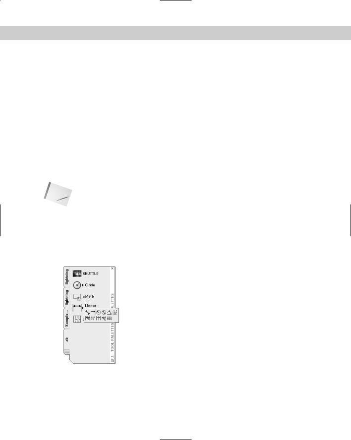
When you create certain types of command tools, the tool palette recognizes the command as one of a group of commands, and creates an entire group, or flyout, of command tools that all use the same properties as the original. This technique works with dimensions and common drawing geometry objects, such as lines and circles. Figure 26-6 shows an example of such a flyout on a tool palette.
Figure 26-6: Creating one dimension tool automatically creates a flyout of all of the dimension tools.
Dragging buttons from a toolbar
You can drag buttons from a toolbar onto a tool palette. These can be the standard toolbar buttons or custom buttons that you’ve created. To transfer toolbar buttons to a tool palette, follow these steps:
Chapter 26 Keeping Control of Your Drawings |
845 |
1.Display the toolbar that you want to use.
2.Choose Tools Customize Tool Palettes. The Customize dialog box opens.
3.One by one, drag the buttons that you want onto the tool palette. (The Customize dialog box doesn’t seem to have any function here, but you can’t drag buttons off of a toolbar without it.)
Copying a tool
You can copy an existing tool to create a new tool, whether a content tool or a command tool. You can then change the tool properties. You can use this technique to create related, but slightly different, tools. For example, you could include a hatch on two different layers. You could also include variations of one dynamic block.
To copy a tool, right-click the tool and choose Copy from the shortcut menu. Then right-click again and choose Paste. The next section explains how to change tool properties.
Setting tool properties
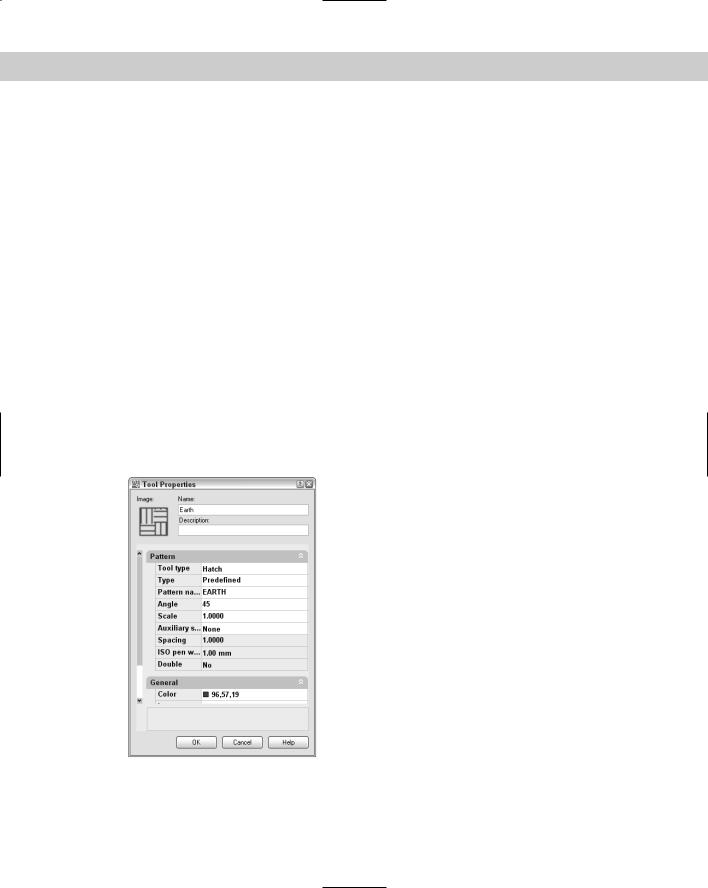
Each tool on a tool palette has properties that you can set. The available properties vary slightly, depending on the type of tool. The properties specify how that tool is inserted into a drawing. Tools inherit their properties from the object that you dragged onto the palette. However, you can change the properties. To set the properties of a tool, right-click it and choose Properties to open the Tool Properties dialog box. Figure 26-7 shows the Tool Properties dialog box for a hatch tool.
Figure 26-7: The Tool Properties dialog box for a block and a hatch pattern.
846 Part V Organizing and Managing Drawings
The middle section of the dialog box contains Insert, Attach, or Pattern properties, and the bottom of the dialog box displays General properties.
To specify any property, click the right column for that property. Either type a new value or choose from the drop-down list. After you’re done, click OK to close the Tool Properties dialog box.
New |
You can now select multiple tools and change their common properties at one time. To select |
Feature |
multiple tools, press Ctrl and click the tools that you want to change. |
|
Adjusting the scale of inserted content
The tools that you create by dragging content from a drawing take their properties from that object, and so they may contain an inherent scale. For example, your hatches, blocks, and xrefs have a certain size. If you need to adjust a scale, you can do so, based on one of the following:
Your overall dimension scale: You set the dimension scale on the Fit tab of the Modify Dimension Style dialog box. The value is stored in the DIMSCALE system variable.
Your plot scale: You set the plot scale in the Plot dialog box.
To set the scale of a hatch, block, or xref tool, right-click the tool and choose Properties. Click the Auxiliary Scale item. Then click the down arrow that appears at the right, and choose either Dimscale or Plot Scale. Click OK. From now on, the block or xref comes into your drawing at the scale that you’ve set in your drawing.
Moving, deleting, and renaming tools and tool palettes
You can change the order of both tool palettes (tabs) in the Tool Palettes window and of tools on a palette.
To move a tool on a palette, drag the tool. A horizontal cursor appears to show you where the tool will go.
To move a palette, right-click the tab itself and choose Move Up or Move Down.
You can also move or copy a tool (drawing, block, or hatch) from one tool palette to another. Follow these steps:
1.Display the tool palette (tab) that contains the item that you want to move.
2.Right-click the item and choose Cut (to move it) or Copy (to copy it).
3.Display the tool palette (tab) where you want to place the item.
4.Right-click any blank area on the tab and choose Paste.
You can use this method to consolidate tabs or reorganize the tools on a tab.
To delete a tool palette, right-click the palette and choose Delete Tool Palette. A warning message is displayed, explaining that you cannot recover the deleted tool palette unless you export it to a file. To delete a tool on a tool palette, right-click the tool and choose Delete Tool. Here, too, you need to confirm the deletion when a warning message appears.
To export a tool palette, you save it to a file. You can then share tool palettes with others. You import and export tool palettes on the Tool Palettes tab in the Customize dialog box. See Chapter 29 for details.
To rename a tool palette, right-click the palette and choose Rename Tool Palette. To rename a tool, right-click the tool and choose Rename. In both situations, type a new name and press Enter.

Chapter 26 Keeping Control of Your Drawings |
847 |
Updating tools
If the source of a tool changes, its icon does not automatically change to match. In this situation, the icon will not accurately represent its tool. To update an icon, use one of the following methods:
Right-click the tool and choose Properties. Click the Source File (or Pattern Name) item, then use the Ellipsis button to choose any other file, block, or hatch pattern, and then immediately choose the correct item again. This technique updates the icon for the tool.
Delete the tool and re-insert it.
If you change a block or dynamic block, you can update its image. Right-click the image and choose Update Tool Image from the shortcut menu.
If you move the source file for a tool, you need to update the tool with the new location:
1.Right-click the tool and choose Properties.
2.In the Tool Properties dialog box, use the Ellipsis button to choose the file again.
3.Click OK.
Setting tool palette options
To work most comfortably with the Tool Palettes window, you can adjust its display options. Right-click any empty area on the tool palette (except the tab itself) and choose from the following options:
Allow Docking: Enables you to dock the tool palette on the left or right side of the drawing area.
Auto-Hide: Collapses the tool palette to just its title bar when the mouse cursor is off the Tool Palettes window. Pass the mouse cursor back over the title bar to expand the tool palette again. You can store the collapsed tool palette outside the application window (if it isn’t fully maximized).
Transparency: Opens the Transparency dialog box. When the tool palette is transparent, you can see the drawing through it. You can specify the amount of transparency or turn it off. Then click OK.
Note Transparency is available only when hardware acceleration is off (which it is by default). Hardware acceleration is governed by your computer’s video card and helps to speed up the display. If you want to use the transparency feature, you can use software acceleration instead (and see if it affects your display speed). Choose Tools Options and click the System tab. In the Current 3D Graphics Display section, click Properties. In the Acceleration section, choose Software. Click Apply & Close and then click OK to close the Options dialog box. Keep in mind that transparency is available only when the palette is not docked. This feature is not available for AutoCAD LT.
View Options: Opens the View Options dialog box. You can change the size and layout of the tool icons on a tool palette. Use the slider to change the size of the icons. Choose from the following display styles:
•Icon only: You see the icon displaying the drawing, block, or hatch, but no text.
848 Part V Organizing and Managing Drawings
•Icon with text: Text is displayed beneath each icon, and the icons are arranged in columns.
•List view: You see one column of icons, with the text to the right of each icon.
You can choose to apply the changes to the current tool palette or to all tool palettes. Click OK when you’re done.
Tip |
If you have docking enabled, but you want to drag the Tool Palettes window without docking |
|
it, press Ctrl as you drag. |
Organizing tool palettes
You may have one set of tool palettes for architectural work and another for mechanical work. For whatever reason, you may want to display one set of tool palettes at one time and another set at another time. For this purpose, you organize tool palettes into groups. I explain how to create these groups in Chapter 29.
To display the various groups, right-click the title bar of the tool palette and choose the group that you want. Using groups helps to avoid clicking through too many tool palettes. After all, the point is instant access. However, you can always display all of the palettes by right-clicking and choosing All Palettes.
Using a tool palette
Inserting a tool from a tool palette is as simple as dragging the tool onto the drawing area. The tool is inserted using the properties specified in the Tool Properties dialog box (discussed previously in this section).
Tools know how to behave. Drag a gradient or hatch into an enclosed area and it automatically fills the area. Drag an xref onto a drawing and you get a prompt, at the command line, for the insertion point. Tools automatically use their properties so that you get a circle on its proper layer or a hatch with the proper scale.
If you want the flexibility to insert a block or hatch with more than one setting, you can insert another copy of the item onto a tool palette. For example, you can place two copies of a hatch pattern on a tool palette and set their properties to different spacing. You would then rename the tools to make the differences clear (for example, lightning1 and lightning 2). You can also copy a tool and then modify it, as I explain in the section “Copying a tool” earlier in this chapter.
On the |
The drawings used in the following exercise on creating and using a tool palette, ab26-c.dwg |
CD-ROM |
and ab26-d.dwg, are in the Drawings folder on the CD-ROM. |
STEPS: Creating and Using a Tool Palette
1.Open ab26-c-dwg from the CD-ROM.
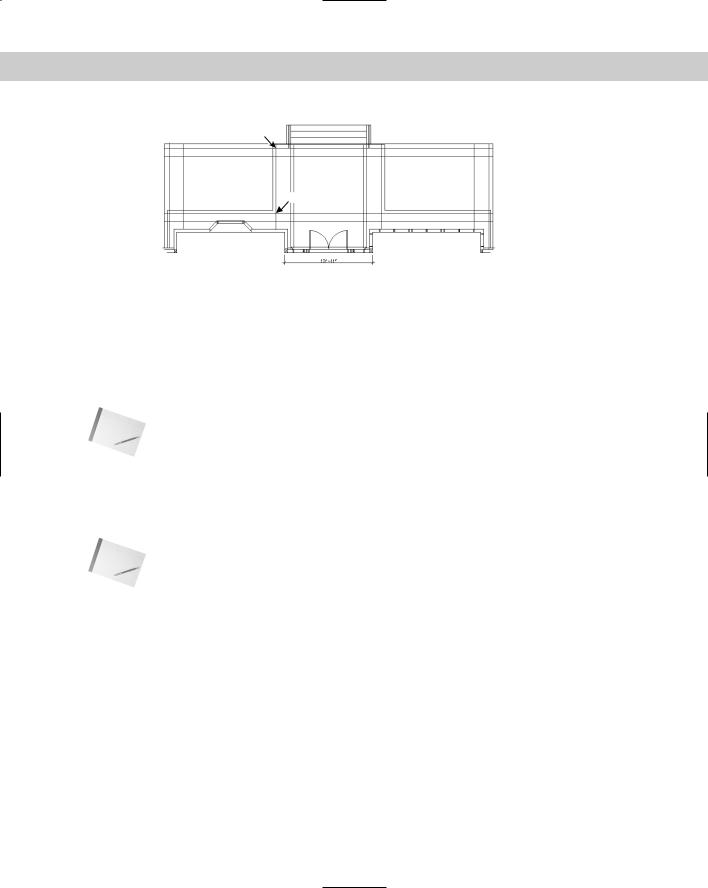
2.Save the file as ab26-02.dwg in your AutoCAD Bible folder. This drawing, shown in Figure 26-8, needs some blocks and a hatch pattern inserted. You’ll also add a dimension.
3.Choose Tools Tool Palettes Window.
Chapter 26 Keeping Control of Your Drawings |
849 |
5
1 |
2 |
3 |
4
Figure 26-8: This back porch needs some columns (which are blocks), some hatching, and a dimension.
4.Choose DesignCenter from the Standard toolbar. In the DesignCenter’s Folder List, navigate to the Drawings folder of your CD-ROM and click the plus sign to the left of ab26-d.dwg. Click the Blocks item to display the two blocks (post and post-structural) in the content area on the right side of the DesignCenter.
5.Right-click any empty area of the tool palette, and choose New Tool Palette. A label appears. Type 2d arch and press Enter. You now have a new tool palette named 2d arch.
Note |
If the tool palette is collapsed when the mouse cursor is not over it, right-click its title bar and |
|
choose Auto-Hide to uncheck this item. |
6.From the content area of the DesignCenter, drag each of the blocks to the new tool palette. An icon appears on the tool palette for each block.
7.In the Folder List of the DesignCenter, navigate to acad.pat or aclt.pat, which contains hatch patterns. Click acad.pat or aclt.pat to display the hatch patterns in the content area.
Note |
To find the location of acad.pat or aclt.pat, choose Tools Options and click the Files tab. |
|
Double-click the first item, Support File Search Path, to display the location of the support files. |
8.Drag User Defined, one of the hatch patterns, to the tool palette. (This hatch pattern is equivalent to choosing User Defined as the Hatch Type in the Hatch and Gradient dialog box. See Chapter 16 for details.) The tool palette now has three items on it. Close or Auto-Hide the DesignCenter.
9.Right-click the User Defined hatch icon and choose Properties to open the Tool Properties dialog box. You want to specify settings so that this hatch pattern will look like scored concrete for the porch floor.
10.In the Tool Properties dialog box, make the following changes and then click OK:
•For the Angle, type 45.
•For the Spacing, type 2' (or 24).
•Click the Double item at the bottom of the Pattern section and then click the arrow at the right side of the row. Choose Yes from the drop-down list.
•Click the Layer item in the General section and choose FLOOR from the dropdown list. (You may have to drag the bottom edge of the dialog box down to see the layer item.)
850 Part V Organizing and Managing Drawings
11.Right-click the hatch tool and choose Rename. Type porch tile and press Enter.
12.Drag the User Defined hatch icon to 1 in Figure 26-8. Then do the same for 2 and 3. These areas are hatched, as shown in Figure 26-9.
13.Activate the Command Tools tab and click the small arrow to the right on the Linear Dimension tool to see the flyout. You could choose any dimension type from this flyout. To place a linear dimension, click the main linear dimension icon. Follow the prompts:
Specify first extension line origin or <select object>: Pick the upper-left corner of the porch.
Specify second extension line origin: Pick the upper-right corner of the porch.
Specify dimension line location or [Mtext/Text/Angle/Horizontal/ Vertical/Rotated]: Pick any location for the dimension line above the steps.
14.Choose Zoom Window from the Zoom flyout on the Standard toolbar, and zoom into the central area of the drawing so that you can still see the double doors at the bottom and the steps at the top.
15.Switch back to the 2d arch tab and click the Post icon. At the Specify insertion point: prompt, pick the intersection at 4 in Figure 26-8. Click the Post-Structural icon. At the prompt, pick the upper-right corner of the post block, as shown in Figure 26-9.
16.Click the Post icon. At the prompt, pick 5 in Figure 26-8. Use the same technique to place the Post-Structural icon at the upper-right corner of the post block. (The posts would then need to be spaced and mirrored to the other side of the porch, but these tasks are not necessary for this exercise.)
17.Right-click the tool palette’s title bar. If Allow Docking is checked, click Allow Docking to uncheck this item. If Auto-Hide is not checked, click Auto-Hide to enable this feature. Move the mouse off the tool palette. It collapses to its title bar. Move the tool palette to the right side of your screen.
18.If you’re working on someone else’s computer, you should delete the tool palette. Move the cursor over the palette to display it. Right-click any blank area and choose Delete Palette. Click OK to confirm the deletion.
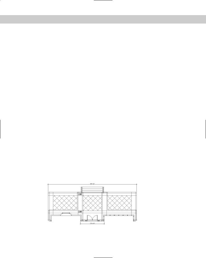
19.Save your drawing. It should look like Figure 26-9.
Figure 26-9: The drawing now has hatches and blocks inserted from the tool palette. It also has a new dimension.