

- •Contents
- •Contents at a Glance
- •Acknowledgments
- •Preface
- •Is This Book for You?
- •How This Book Is Organized
- •How to Use This Book
- •Doing the Exercises
- •Conventions Used in This Book
- •What the Icons Mean
- •About the CD-ROM
- •Other Information
- •Contacting the Author
- •Foreword
- •Credits
- •About the Author
- •Summary
- •AutoCAD’s Advantages
- •Comparing AutoCAD and AutoCAD LT
- •Starting AutoCAD and AutoCAD LT
- •Creating a New Drawing
- •Using the AutoCAD and AutoCAD LT Interface
- •Creating a New Folder
- •Using the Interface
- •Saving a Drawing
- •Closing a Drawing and Exiting from AutoCAD and AutoCAD LT
- •Summary
- •Creating a New Drawing from a Template
- •Working with Templates
- •Opening a Drawing with Default Settings
- •Opening an Existing Drawing
- •Using an Existing Drawing as a Prototype
- •Saving a Drawing Under a New Name
- •Summary
- •The Command Line and Dynamic Input
- •Command Techniques
- •Of Mice and Pucks
- •Getting Help
- •Summary
- •Typing Coordinates
- •Displaying Coordinates
- •Picking Coordinates on the Screen
- •Overriding Coordinate Settings
- •Locating Points
- •Summary
- •Choosing Unit Types
- •Drawing Limits
- •Understanding Scales
- •Creating a Title Block
- •Specifying Common Setup Options
- •Customizing with the MVSETUP Command
- •Using the Setup Wizards
- •Summary
- •Using the LINE Command
- •Drawing Rectangles
- •Drawing Polygons
- •Creating Construction Lines
- •Creating Rays
- •Summary
- •Drawing Circles
- •Drawing Arcs
- •Creating Ellipses and Elliptical Arcs
- •Making Donuts
- •Placing Points
- •Summary
- •Panning
- •Using the ZOOM Command
- •Using Aerial View
- •Saving Named Views
- •Working with Tiled Viewports
- •Using Snap Rotation
- •Understanding User Coordinate Systems
- •Creating Isometric Drawings
- •Summary
- •Editing a Drawing
- •Selecting Objects
- •Summary
- •Copying and Moving Objects
- •Resizing Commands
- •Using Construction Commands
- •Creating a Revision Cloud
- •Hiding Objects with a Wipeout
- •Double-Clicking to Edit Objects
- •Grips
- •Editing with the Properties Palette
- •Selection Filters
- •Groups
- •Summary
- •Working with Layers
- •Changing Object Color, Linetype, and Lineweight
- •Working with Linetype Scales
- •Importing Layers and Linetypes from Other Drawings
- •Matching Properties
- •Summary
- •Drawing-Level Information
- •Object-Level Information
- •Measurement Commands
- •AutoCAD’s Calculator
- •Summary
- •Creating Single-Line Text
- •Understanding Text Styles
- •Creating Multiline Text
- •Creating Tables
- •Inserting Fields
- •Managing Text
- •Finding Text in Your Drawing
- •Checking Your Spelling
- •Customizing the spelling dictionary
- •Summary
- •Working with Dimensions
- •Drawing Linear Dimensions
- •Drawing Aligned Dimensions
- •Creating Baseline and Continued Dimensions
- •Dimensioning Arcs and Circles
- •Dimensioning Angles
- •Creating Ordinate Dimensions
- •Drawing Leaders
- •Using Quick Dimension
- •Editing Dimensions
- •Summary
- •Understanding Dimension Styles
- •Defining a New Dimension Style
- •Changing Dimension Styles
- •Creating Geometric Tolerances
- •Summary
- •Creating and Editing Polylines
- •Drawing and Editing Splines
- •Creating Regions
- •Creating Boundaries
- •Creating Hatches
- •Creating and Editing Multilines
- •Creating Dlines
- •Using the SKETCH Command
- •Digitizing Drawings with the TABLET Command
- •Summary
- •Preparing a Drawing for Plotting or Printing
- •Creating a Layout in Paper Space
- •Working with Plot Styles
- •Plotting a Drawing
- •Summary
- •Combining Objects into Blocks
- •Inserting Blocks and Files into Drawings
- •Managing Blocks
- •Creating and Using Dynamic Blocks
- •Using Windows Features
- •Working with Attributes
- •Summary
- •Understanding External References
- •Editing an Xref within Your Drawing
- •Controlling Xref Display
- •Managing Xrefs
- •Summary
- •Preparing for Database Connectivity
- •Connecting to Your Database
- •Linking Data to Drawing Objects
- •Creating Labels
- •Querying with the Query Editor
- •Working with Query Files
- •Summary
- •Working with 3D Coordinates
- •Using Elevation and Thickness
- •Working with the User Coordinate System
- •Summary
- •Working with the Standard Viewpoints
- •Using DDVPOINT
- •Working with the Tripod and Compass
- •Displaying a Quick Plan View
- •Shading Your Drawing
- •Using 3D Orbit
- •Using Tiled Viewports
- •Defining a Perspective View
- •Laying Out 3D Drawings
- •Summary
- •Drawing Surfaces with 3DFACE
- •Drawing Surfaces with PFACE
- •Creating Polygon Meshes with 3DMESH
- •Drawing Standard 3D Shapes
- •Drawing a Revolved Surface
- •Drawing an Extruded Surface
- •Drawing Ruled Surfaces
- •Drawing Edge Surfaces
- •Summary
- •Drawing Standard Shapes
- •Creating Extruded Solids
- •Drawing Revolved Solids
- •Creating Complex Solids
- •Sectioning and Slicing Solids
- •Using Editing Commands in 3D
- •Editing Solids
- •Listing Solid Properties
- •Summary
- •Understanding Rendering
- •Creating Lights
- •Creating Scenes
- •Working with Materials
- •Using Backgrounds
- •Doing the Final Render
- •Summary
- •Accessing Drawing Components with the DesignCenter
- •Accessing Drawing Content with Tool Palettes
- •Setting Standards for Drawings
- •Organizing Your Drawings
- •Working with Sheet Sets
- •Maintaining Security
- •Keeping Track of Referenced Files
- •Handling Errors and Crashes
- •Managing Drawings from Prior Releases
- •Summary
- •Importing and Exporting Other File Formats
- •Working with Raster Images
- •Pasting, Linking, and Embedding Objects
- •Summary
- •Sending Drawings
- •Opening Drawings from the Web
- •Creating Object Hyperlinks
- •Publishing Drawings
- •Summary
- •Working with Customizable Files
- •Creating Keyboard Shortcuts for Commands
- •Customizing Toolbars
- •Customizing Tool Palettes
- •Summary
- •Creating Macros with Script Files
- •Creating Slide Shows
- •Creating Slide Libraries
- •Summary
- •Creating Linetypes
- •Creating Hatch Patterns
- •Summary
- •Creating Shapes
- •Creating Fonts
- •Summary
- •Working with the Customization File
- •Customizing a Menu
- •Summary
- •Introducing Visual LISP
- •Getting Help in Visual LISP
- •Working with AutoLISP Expressions
- •Using AutoLISP on the Command Line
- •Creating AutoLISP Files
- •Summary
- •Creating Variables
- •Working with AutoCAD Commands
- •Working with Lists
- •Setting Conditions
- •Managing Drawing Objects
- •Getting Input from the User
- •Putting on the Finishing Touches
- •Summary
- •Understanding Local and Global Variables
- •Working with Visual LISP ActiveX Functions
- •Debugging Code
- •Summary
- •Starting to Work with VBA
- •Writing VBA Code
- •Getting User Input
- •Creating Dialog Boxes
- •Modifying Objects
- •Debugging and Trapping Errors
- •Moving to Advanced Programming
- •Summary
- •A Final Word
- •Installing AutoCAD and AutoCAD LT
- •Configuring and Using Workspaces
- •Configuring AutoCAD
- •Starting AutoCAD Your Way
- •Configuring a Plotter
- •Discovering AutoCAD and AutoCAD LT
- •Accessing Technical Support
- •Autodesk User Groups
- •Internet Resources
- •System Requirements
- •Using the CD-ROM with Microsoft Windows
- •What’s on the CD-ROM
- •Troubleshooting
- •Index
806 Part IV Drawing in Three Dimensions
3.Choose Render from the Render toolbar. In the Rendering Procedures section of the Render dialog box, check the Crop Window check box. In the Rendering Options
section, check the Render Cache check box.
4.Click Render.
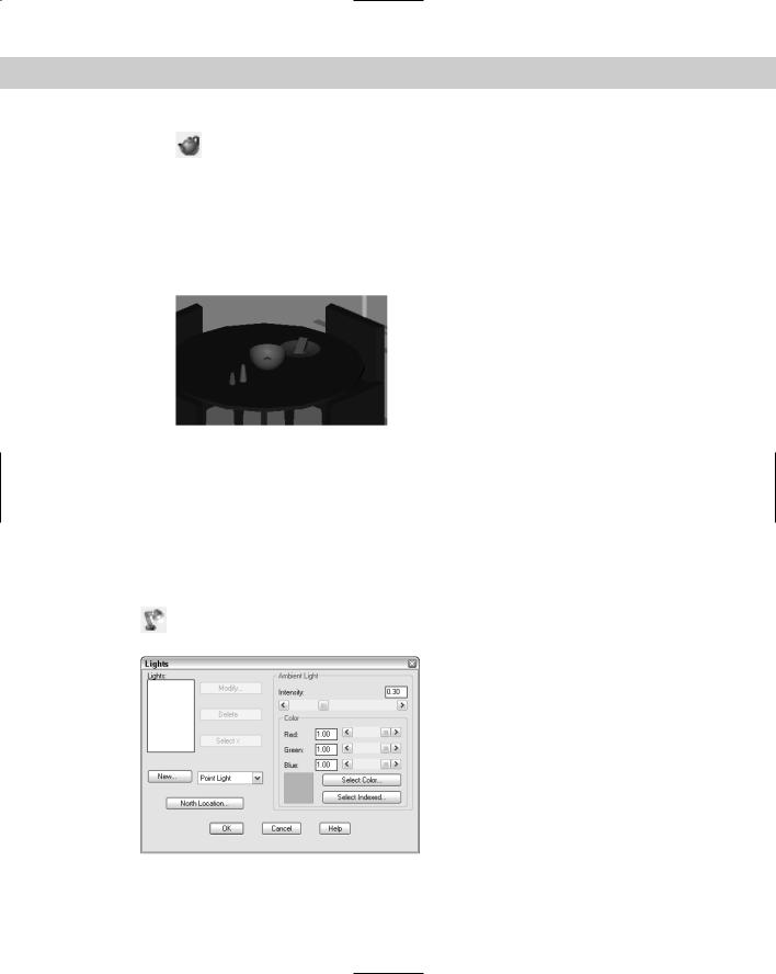
5.At the Pick crop window to render: prompt, pick a window similar to that shown in Figure 25-3. Wait until AutoCAD renders the drawing.
6.Save your drawing. It should look like Figure 25-3. As you can see, the rendering is too dark and the objects need realistic materials.
Figure 25-3: An initial rendering using default options and a crop window.
Creating Lights
When you render using the default options, AutoCAD uses one light source from behind the viewer, which falls on the objects in the view. However, that is rarely enough, nor is it realistic. AutoCAD offers four types of lights to give you a great deal of flexibility in creating a realistic scene. If you plan to cast shadows in your rendering, the proper placement of lights is most important.
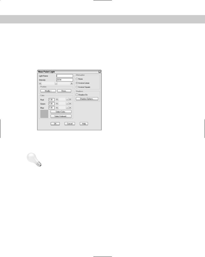
To create lights, choose Lights from the Render toolbar to open the Lights dialog box, shown in Figure 25-4.
Figure 25-4: The Lights dialog box.
Chapter 25 Rendering in 3D 807
Assigning color to a light
The process of assigning a color to a light applies to all types of lights. Light colors are somewhat different from pigment colors, which are more familiar. You know that there are three primary pigment colors — red, yellow, and blue — and you know what colors you get when you mix them. The three primary light colors are red, green, and blue (RGB). Their mixtures are different, as well; for example, red and green make yellow. White light is the sum of all colors of light together. Black is the absence of any colors of light.
In addition to the RGB light color system, there is the HLS (hue, lightness, saturation) system. Instead of mixing primary colors, you choose the color from a range of hues and then vary its lightness (brightness) and saturation (intensity).
You have three options for choosing a color for a light:
RGB: The RGB system enables you to define colors by the amount of each primary light color. You can use the slider bars or type in a number from 0 to 1. When all three are set to 1, you get white light, the default.
True Color: Choose Select Color to open the Select Color dialog box. With the True Color tab on top, you can select colors either by an RGB or an HLS system. Remember that, an HLS system determines color by hue, lightness, and saturation settings. Hue is the color. Lightness, or brightness, is the amount of white that the color contains. Saturation is the amount of black that the color contains. You can also click the Color Book tab to use a color from a color book. (See Chapter 11 for a full discussion of using true color and color books.)
ACI: Choose Select Indexed to use the AutoCAD Color Index (ACI) system. AutoCAD opens the Select Color dialog box with the Index Color tab on top so that you can choose a color.
Tip |
In most cases, white light is fine. You can get some unexpected results when using colored |
|
lights on colored objects. |
Setting the north location
Click North Location to open the North Location dialog box and to set which direction is north. Setting the north location is important if you want to use the Sun Angle Calculator to create a distant light and if you want to create shadows. By default, north is the positive Y direction in the World Coordinate System (WCS). To change the default, type a new angle in the Angle box, use the slider bar, or click the “clock face” to specify the new angle. The positive Y axis is at 0 degrees, the positive X axis is at 90 degrees, and so on clockwise.
If you’ve saved a UCS, you can choose it from the list on the right side of the dialog box. AutoCAD uses the Y axis in that UCS as the default North direction.
Setting the ambient light
Ambient light is background light that has no source or target. It illuminates all surfaces in your drawing equally. It can, however, have a color. By default, ambient light is set at 0.30. Use the Intensity slider bar to change the setting, or type a number from 0 to 1. Making ambient light too high results in a rendering that looks like an overexposed image. Use a lower setting for night scenes.
808 Part IV Drawing in Three Dimensions
Creating a point light
A point light is equivalent to a typical light bulb or a candle. It comes from a specific location and radiates in all directions. A point light attenuates, meaning that the intensity lessens as the distance away from the light’s source increases.
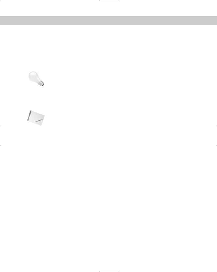
To create a new point light, choose Point Light from the drop-down list next to the New button. Then click New to open the New Point Light dialog box, shown in Figure 25-5.
|
Figure 25-5: The New Point Light dialog box. |
|
Name |
|
In the Light Name text box, type a name for the light, no more than eight characters long. |
Tip |
Use a name that makes it clear that the light is a point light. Keep the name short; a simple |
|
sequence of P1, P2 is often sufficient. However, you could also use P-overhd and P-door or |
|
something similar. |
|
Attenuation |
|
Set the attenuation, which is the manner in which the light loses intensity as the distance from |
|
its source increases. You have three choices: |
None: The light doesn’t lose intensity.
Inverse Linear: The light loses intensity in a linear manner, so that at 2 units from its source the light is half as intense, and at 4 units away the light is one-quarter as intense. This is the default.
Inverse Square: The light loses intensity at the square of the distance, so that at 2 units from its source the light is one-quarter as intense and at 4 units away the light is onesixteenth as intense. Setting the attenuation to inverse square means that the intensity of the light drops off very quickly.
Intensity
Set the intensity, or brightness, of the light in the Intensity text box or use the slider bar. AutoCAD sets the maximum brightness based on the attenuation and the drawing extents.
Chapter 25 Rendering in 3D 809
If you chose inverse linear attenuation, the maximum intensity is twice the distance from the lower-left corner to the upper-right corner of the extents of the drawing. The default is half of the maximum.
If you chose inverse square attenuation, the maximum intensity is twice the square of the extents (the distance from the lower-left corner to the upper-right corner of the drawing).
If you chose no attenuation, the maximum intensity is 1.
Tip |
Set the intensity to 0 (zero) to turn a light off. You can use this technique to switch a scene from |
|
a day view to a night view or to experiment with different lights without having to delete them. |
Position
The position of the light is quite important, especially if you decide to create shadows. If you set the XY coordinates in plan view, be sure to set the proper Z coordinate as well. In an architectural drawing, you don’t want your lights to be coming from the floor! However, in a mechanical drawing, it might be appropriate to light your model from any angle.
Note You can also set the transparency of materials; for example, you can use transparency for windows. If you create an opaque lampshade and place a light inside it, light will get out only through the top and bottom.
Choose Show to see the current position and target of the light. Choose Modify to temporarily return to your drawing to pick a position.
Use object snaps or point filters to specify the position of your lights. If there are no objects available, work out the position in advance and place easily visible point objects there. You can then snap to the point objects using the Node object snap. You can type the absolute coordinates. You can also use the From object snap to specify a coordinate based on a point on the model.
Color
Set the color of the light. Setting light color is discussed in the previous section “Assigning color to a light.”
Shadows
Check Shadow On if you want to create shadows. Choose Shadow Options to set the type of shadows that you want, and set Shadow Map Size and Softness. Creating shadows adds significantly to rendering time. When you’re done creating the point light, click OK.
I cover shadows in the “Creating shadows” section at the end of the discussion on lights.
Creating a spotlight
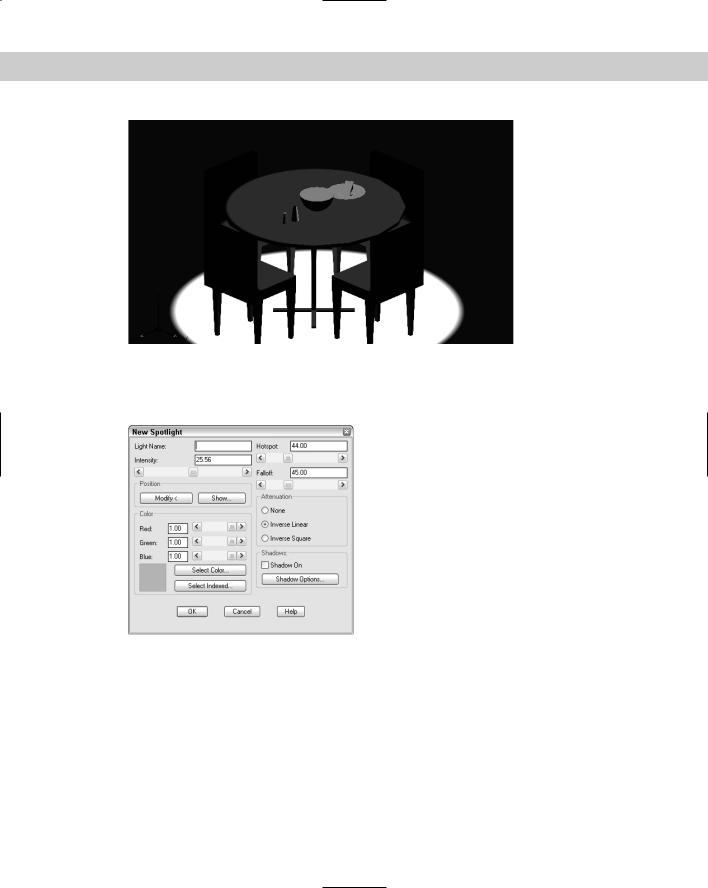
A spotlight differs from a point light in that it has a direction. As a result, you not only specify its location but also its target — two coordinates instead of one. In addition, a spotlight has a brighter center called the hotspot. Outside the bright center is a ring of lesser brightness called the falloff. Figure 25-6 shows the same scene used previously in this chapter, but with one overhead spotlight.
810 Part IV Drawing in Three Dimensions
Figure 25-6: A rendering with one spotlight overhead.
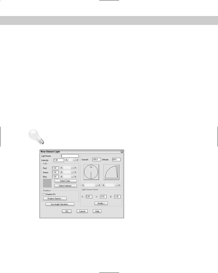
To create a new spotlight, choose Spotlight from the drop-down list next to the New button in the Lights dialog box. Then click New to open the New Spotlight dialog box, shown in Figure 25-7.
Figure 25-7: The New Spotlight dialog box.
Name
In the Light Name text box, type a name for the light. As mentioned earlier for point lights, use a name that makes it clear that the light is a spotlight. Keep the name short. A simple sequence of S1, S2 is often sufficient. However, you could also use S-roof and S-door or something similar, but the name cannot be more than eight characters long.
Hotspot and falloff
Set the hotspot and falloff angles. These angles emanate from the spotlight in the direction of the light’s target. The maximum angle for both is 160 degrees. If the hotspot and falloff angles are the same, there is no falloff — the entire spotlight is bright. The defaults are 44 degrees for the hotspot and 45 degrees for the falloff. This does not leave very much falloff area. You may need to experiment to get the desired result.
Chapter 25 Rendering in 3D 811
To set the hotspot and falloff angles, type the angles in the text boxes or use the slider bars.
The rest of the options for a spotlight are the same as for a point light. Set the attenuation, intensity, position, color, and shadows. When you’re done creating the spotlight, click OK.
|
Creating a distant light |
|
A distant light is equivalent to the sun. Its rays come from so far away that, for all practical |
|
purposes, they’re parallel. A distant light does not attenuate (unless you’re drawing a model |
|
on Pluto). |
|
To create a new distant light, choose Distant Light from the drop-down list next to the New |
|
button in the Lights dialog box. Then click New to open the New Distant Light dialog box, |
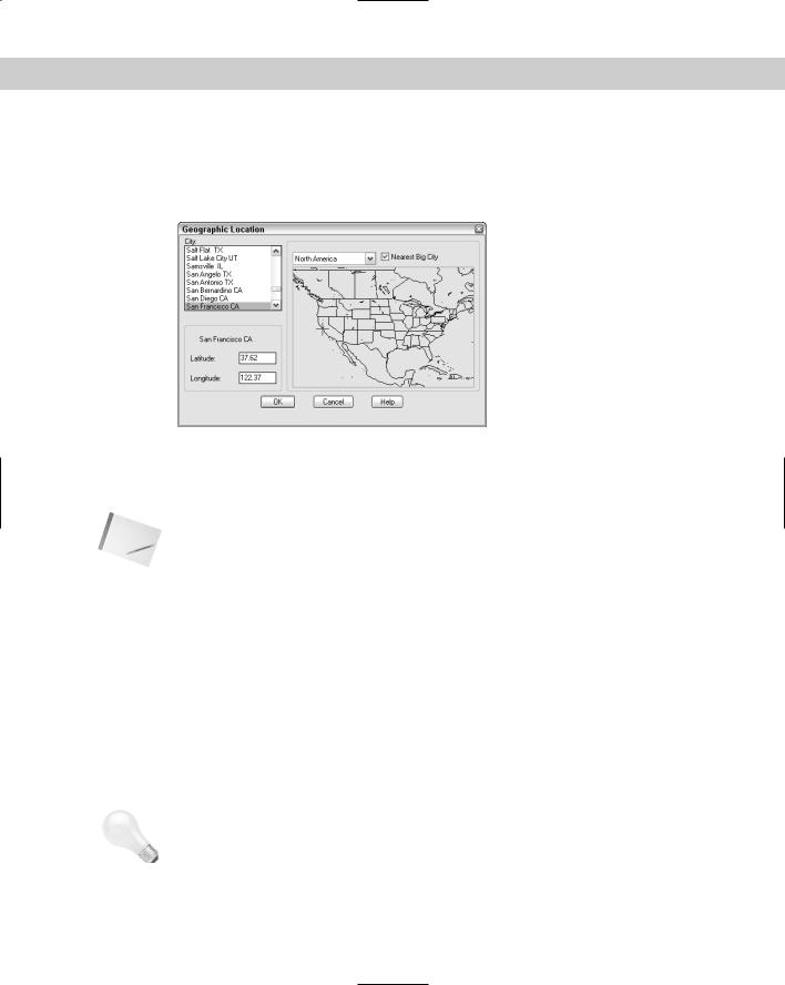
|
shown in Figure 25-8. |
|
Name |
|
In the Light Name text box, type a name for the light. As mentioned earlier for point lights and |
|
spotlights, use a name that makes it clear that the light is a distant light. Keep the name short. |
|
Intensity |
|
Set the intensity, or brightness, of the light in the Intensity text box or use the slider bar. The |
|
intensity can range from 0 to 1. |
Tip |
To turn the distant light off, set the intensity to 0 (zero). You can use this technique to switch |
|
a scene from a day view to a night view or to experiment with different lights. |
Figure 25-8: The New Distant Light dialog box.
Position
The position of the light is quite important, especially if you decide to create shadows. If you set the XY coordinates in plan view, be sure to set the proper Z coordinate as well. Generally, you position a distant light at the extents of your drawing.
You have three ways to specify the position of a distant light, as described in the following sections.
812 Part IV Drawing in Three Dimensions
Azimuth and altitude
The azimuth is the angle in the XY plane — North is located at 0 degrees. Use a positive angle to move clockwise from North and a negative angle to move counterclockwise from North. Values can range from –180 to 180. (Both –180 and 180 would represent South.) The altitude is the angle from the XY plane. The slider bar lets you enter angles from 0 to 90, or you can type in angles from –90 to 90. (An altitude of –90 would mean the light was coming from beneath the model.)
Light source vector
This is just another way to specify the direction of the light. Click Modify to return temporarily to your drawing. AutoCAD prompts you to enter To and From coordinates to specify the direction. This only sets the direction of the light. AutoCAD places the light outside the model.
Sun Angle Calculator
Click Sun Angle Calculator to open the Sun Angle Calculator dialog box, shown in Figure 25-9.
Figure 25-9: The Sun Angle Calculator dialog box.
Use the Sun Angle Calculator when you’re using a distant light to simulate the sun. The calculator locates the sun based on the latitude and longitude of the model’s location and the time of day. Naturally, you would use this for architectural or surveying drawings. It’s fun, too.
Use the left side of the dialog box to specify the information that Render needs to calculate the position of the sun. Follow these steps to complete the dialog box:
1.Type the date or use the slider bar.
2.Type the time using 24-hour format or use the slider bar.
3.Choose the time zone from the drop-down list. Check Daylight Savings, if applicable.
4.Specify the latitude and longitude by typing them in or using the slider bars. Latitude goes from 0 degrees (the equator) to 90 degrees (the North or South Pole). Longitude goes from 0 degrees in Greenwich, England, to 180 degrees at the opposite side of the globe.
5.Specify the hemispheres: North or South and East or West.
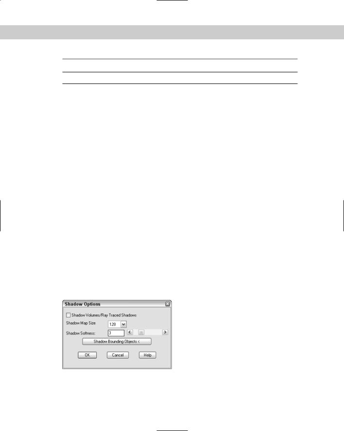
6.If you don’t know the latitude and/or longitude, click Geographic Location to open the Geographic Location dialog box, shown in Figure 25-10.
Choose the continent from the drop-down list above the map. The appropriate map appears. (Try choosing various continents — it’s a great way to travel.)
Chapter 25 Rendering in 3D 813
Check Nearest Big City if your model is in a big city. Then click the map. The blue crosshairs jump to the nearest big city. You can also choose from the City list; the blue crosshairs move to the proper location on the map.
When you’re done, click OK.
Figure 25-10: Use the Geographic Location dialog box to determine latitude and longitude for specific locations.
7.In the Sun Angle Calculator dialog box, click OK to return to the New Distant Light dialog box.
Note |
If you forgot to set the north location, choose North Location now. None of the sun calculations |
|
works properly if North is not properly defined. See “Setting the north location,” earlier in this |
|
chapter. |
|
Color |
|
Use this section to set the color of the light. Setting light color is discussed previously in the |
|
section “Assigning color to a light.” |
|
Shadows |
|
Check Shadow On if you want to create shadows. Choose Shadow Options to set the type of |
|
shadows that you want, and set Shadow Map Size and Softness. I cover shadows in the next |
|
section. After you finish defining the distant light, click OK to return to the Lights dialog box. |
|
Creating shadows |
|
Shadows add greatly to the realism of your rendered image. They also add greatly to the ren- |
|
dering time. |
Tip |
For your practice renderings while you’re creating lights and materials, turn shadows off in |
|
the Render dialog box. Shadows significantly add to rendering time, and you’ll do a lot of |
|
waiting. When you’re satisfied with the other settings, turn shadows on. |
|
Types of shadows |
Shadows add dramatically to the realism of your rendering. AutoCAD creates three different types of shadows. Table 25-1 compares these types of shadows.
814 Part IV Drawing in Three Dimensions
Table 25-1: Shadow Characteristics
Type |
Which Renderer to Use Description |
Characteristics |
Volumetric Photo Real or Photo |
Based on volume of space |
Raytrace |
cast by object’s shadow |
Hard edges, outlines are approximate, affected by color of transparent objects
Maps |
Photo Real or Photo |
Based on the map size that |
|
Raytrace |
you set |
Soft edges that you can adjust, not affected by the color of transparent objects
Raytraced Photo Raytrace |
Calculated by tracing the |
Hard edges, accurate outlines, |
|
path of rays from a light |
affected by color of transparent |
|
|
objects |
|
|
|
Base your choice of the type of shadows that you want on the shadow characteristics and your needs.
Shadow settings
To create shadows, you need to turn on shadows in two places. When you create a new light, you check Shadow On in the dialog box that you use to create the new light. In addition, you need to check Shadows in the Rendering Options section of the Render dialog box. This shadows option is available only if you choose Photo Real or Photo Raytrace as the type of rendering in the Render dialog box.
You set shadow settings when you create or modify a light source. Click Shadow Options to open the Shadow Options dialog box, shown in Figure 25-11.
Check the Shadow Volumes/Ray Traced Shadows check box to create volumetric shadows with Photo Real rendering, or raytraced shadows with Photo Raytrace rendering. The shadow map settings are disabled.
If you uncheck the Shadow Volumes/Ray Traced Shadows check box, you can create a shadow map. You can set the shadow map size from 64 to 4,096 pixels. Larger map sizes are more accurate but take longer to render.
Figure 25-11: The Shadow Options dialog box.
Chapter 25 Rendering in 3D 815
Set the shadow softness from 1 to 10 pixels. This determines the number of pixels at the edge of the shadow that are blended into the rest of the image, thus creating the soft effect. AutoCAD recommends using a setting from 2 to 4.
Choose Shadow Bounding Objects to temporarily return to the drawing to select objects for creating a bounding box that AutoCAD uses to clip the shadow maps.
On the |
The drawing used in the following exercise on creating lights and shadows, ab25-a.dwg, is |
CD-ROM |
in the Drawings folder on the CD-ROM. |
STEPS: Creating Lights and Shadows
1.Open ab25-a.dwg from the CD-ROM. OSNAP should be on. Set a running object snap for endpoint.
2.Save the file as ab25-02.dwg in your AutoCAD Bible folder. If the Render toolbar is not open, right-click any toolbar and choose Render.
3.Choose Lights from the Render toolbar. Choose Point Light from the drop-down list next to the New button. Click New to open the New Point Light dialog box.
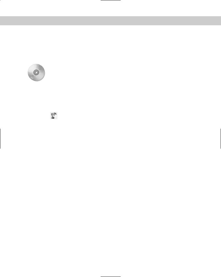
4.Type P1 in the Light Name text box. Click Modify. AutoCAD returns you to your drawing. Click Pan Realtime and pan to the right a couple of times until you see the floor lamp, as shown in Figure 25-12. Press Esc to exit Pan mode. At the Enter light location <current>: prompt, pick the endpoint shown in Figure 25-12. AutoCAD returns you to the New Point Light dialog box.
5.Set the Intensity to 250. In the Color section, click Select Indexed and choose the yellow box. Notice that AutoCAD adjusts the RGB settings. Click OK.
6.Click the Shadow On check box. Click OK to return to the Lights dialog box.
7.Choose Spotlight from the drop-down box and click New. Type S1 in the Light Name text box. Set the Intensity to 250. Click Modify. At the Enter light target <current>:
prompt, pick an endpoint at the top of the bowl on the table. At the Enter light location <current>: prompt, type @0,0,5' to place the light directly over the table as a light hanging from the ceiling.
8.Set the falloff to 55.00 and click the Shadow On check box. Click OK to return to the Lights dialog box.
9.Choose Distant Light from the drop-down box and click New. Type D1 in the Light Name text box. Click the Shadow On check box.
10.Click Sun Angle Calculator. Set the date to 9/1. Set the time to 8:00 in the morning. (You’re having breakfast.) Set the time zone to CST. Click the Daylight Savings check box. Set the latitude to 41.00 and the longitude to 91.57. The two drop-down list boxes below should read North and West. Click Geographic Locator to see where you ended up. (If you typed in the right latitude and longitude, the blue cross should be in southeast Iowa.) Click OK until you return to the Lights dialog box.
11.In the Lights dialog box, click North Location. Type 90 degrees in the text box. Click OK twice to return to your drawing.
12.Choose View Named Views. Choose Render1, click Set Current, and click OK.
816 Part IV Drawing in Three Dimensions
Figure 25-12: Picking the point light location.
13.Choose Render from the Render toolbar. The Crop Window check box should be unchecked. Change the Light Icon Scale to 24 so that you can see the icons that AutoCAD creates at the location of each light you’ve created. (You should use the drawing scale factor.) In the Rendering Type drop-down list, choose Photo Real. Shadows should be unchecked. Click Render. The rendering should take less than a minute. It should look like Figure 25-13. There is more than enough light this time — but remember, you wouldn’t normally eat breakfast with all of the lights on. Notice the effect of the yellow point light.
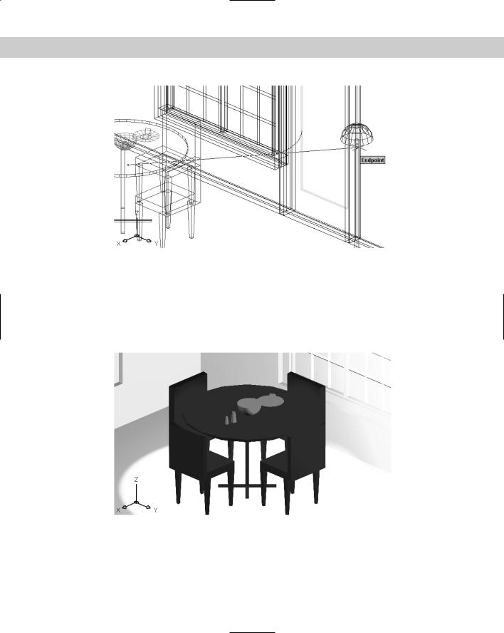
Figure 25-13: A rendering with lights but no shadows.
14.Choose Render again. Check Shadows in the Rendering Options section. Click Render. Notice that the rendering takes much longer. Wow! Lots of shadows. This rendering also makes it clear that no light is coming through the windows. (See the “Creating Scenes” section to learn how to make materials transparent.) The rendering should look like Figure 25-14.
15.Save your drawing. If you’re continuing on to the next exercise, keep this drawing open.