

- •Contents
- •Contents at a Glance
- •Acknowledgments
- •Preface
- •Is This Book for You?
- •How This Book Is Organized
- •How to Use This Book
- •Doing the Exercises
- •Conventions Used in This Book
- •What the Icons Mean
- •About the CD-ROM
- •Other Information
- •Contacting the Author
- •Foreword
- •Credits
- •About the Author
- •Summary
- •AutoCAD’s Advantages
- •Comparing AutoCAD and AutoCAD LT
- •Starting AutoCAD and AutoCAD LT
- •Creating a New Drawing
- •Using the AutoCAD and AutoCAD LT Interface
- •Creating a New Folder
- •Using the Interface
- •Saving a Drawing
- •Closing a Drawing and Exiting from AutoCAD and AutoCAD LT
- •Summary
- •Creating a New Drawing from a Template
- •Working with Templates
- •Opening a Drawing with Default Settings
- •Opening an Existing Drawing
- •Using an Existing Drawing as a Prototype
- •Saving a Drawing Under a New Name
- •Summary
- •The Command Line and Dynamic Input
- •Command Techniques
- •Of Mice and Pucks
- •Getting Help
- •Summary
- •Typing Coordinates
- •Displaying Coordinates
- •Picking Coordinates on the Screen
- •Overriding Coordinate Settings
- •Locating Points
- •Summary
- •Choosing Unit Types
- •Drawing Limits
- •Understanding Scales
- •Creating a Title Block
- •Specifying Common Setup Options
- •Customizing with the MVSETUP Command
- •Using the Setup Wizards
- •Summary
- •Using the LINE Command
- •Drawing Rectangles
- •Drawing Polygons
- •Creating Construction Lines
- •Creating Rays
- •Summary
- •Drawing Circles
- •Drawing Arcs
- •Creating Ellipses and Elliptical Arcs
- •Making Donuts
- •Placing Points
- •Summary
- •Panning
- •Using the ZOOM Command
- •Using Aerial View
- •Saving Named Views
- •Working with Tiled Viewports
- •Using Snap Rotation
- •Understanding User Coordinate Systems
- •Creating Isometric Drawings
- •Summary
- •Editing a Drawing
- •Selecting Objects
- •Summary
- •Copying and Moving Objects
- •Resizing Commands
- •Using Construction Commands
- •Creating a Revision Cloud
- •Hiding Objects with a Wipeout
- •Double-Clicking to Edit Objects
- •Grips
- •Editing with the Properties Palette
- •Selection Filters
- •Groups
- •Summary
- •Working with Layers
- •Changing Object Color, Linetype, and Lineweight
- •Working with Linetype Scales
- •Importing Layers and Linetypes from Other Drawings
- •Matching Properties
- •Summary
- •Drawing-Level Information
- •Object-Level Information
- •Measurement Commands
- •AutoCAD’s Calculator
- •Summary
- •Creating Single-Line Text
- •Understanding Text Styles
- •Creating Multiline Text
- •Creating Tables
- •Inserting Fields
- •Managing Text
- •Finding Text in Your Drawing
- •Checking Your Spelling
- •Customizing the spelling dictionary
- •Summary
- •Working with Dimensions
- •Drawing Linear Dimensions
- •Drawing Aligned Dimensions
- •Creating Baseline and Continued Dimensions
- •Dimensioning Arcs and Circles
- •Dimensioning Angles
- •Creating Ordinate Dimensions
- •Drawing Leaders
- •Using Quick Dimension
- •Editing Dimensions
- •Summary
- •Understanding Dimension Styles
- •Defining a New Dimension Style
- •Changing Dimension Styles
- •Creating Geometric Tolerances
- •Summary
- •Creating and Editing Polylines
- •Drawing and Editing Splines
- •Creating Regions
- •Creating Boundaries
- •Creating Hatches
- •Creating and Editing Multilines
- •Creating Dlines
- •Using the SKETCH Command
- •Digitizing Drawings with the TABLET Command
- •Summary
- •Preparing a Drawing for Plotting or Printing
- •Creating a Layout in Paper Space
- •Working with Plot Styles
- •Plotting a Drawing
- •Summary
- •Combining Objects into Blocks
- •Inserting Blocks and Files into Drawings
- •Managing Blocks
- •Creating and Using Dynamic Blocks
- •Using Windows Features
- •Working with Attributes
- •Summary
- •Understanding External References
- •Editing an Xref within Your Drawing
- •Controlling Xref Display
- •Managing Xrefs
- •Summary
- •Preparing for Database Connectivity
- •Connecting to Your Database
- •Linking Data to Drawing Objects
- •Creating Labels
- •Querying with the Query Editor
- •Working with Query Files
- •Summary
- •Working with 3D Coordinates
- •Using Elevation and Thickness
- •Working with the User Coordinate System
- •Summary
- •Working with the Standard Viewpoints
- •Using DDVPOINT
- •Working with the Tripod and Compass
- •Displaying a Quick Plan View
- •Shading Your Drawing
- •Using 3D Orbit
- •Using Tiled Viewports
- •Defining a Perspective View
- •Laying Out 3D Drawings
- •Summary
- •Drawing Surfaces with 3DFACE
- •Drawing Surfaces with PFACE
- •Creating Polygon Meshes with 3DMESH
- •Drawing Standard 3D Shapes
- •Drawing a Revolved Surface
- •Drawing an Extruded Surface
- •Drawing Ruled Surfaces
- •Drawing Edge Surfaces
- •Summary
- •Drawing Standard Shapes
- •Creating Extruded Solids
- •Drawing Revolved Solids
- •Creating Complex Solids
- •Sectioning and Slicing Solids
- •Using Editing Commands in 3D
- •Editing Solids
- •Listing Solid Properties
- •Summary
- •Understanding Rendering
- •Creating Lights
- •Creating Scenes
- •Working with Materials
- •Using Backgrounds
- •Doing the Final Render
- •Summary
- •Accessing Drawing Components with the DesignCenter
- •Accessing Drawing Content with Tool Palettes
- •Setting Standards for Drawings
- •Organizing Your Drawings
- •Working with Sheet Sets
- •Maintaining Security
- •Keeping Track of Referenced Files
- •Handling Errors and Crashes
- •Managing Drawings from Prior Releases
- •Summary
- •Importing and Exporting Other File Formats
- •Working with Raster Images
- •Pasting, Linking, and Embedding Objects
- •Summary
- •Sending Drawings
- •Opening Drawings from the Web
- •Creating Object Hyperlinks
- •Publishing Drawings
- •Summary
- •Working with Customizable Files
- •Creating Keyboard Shortcuts for Commands
- •Customizing Toolbars
- •Customizing Tool Palettes
- •Summary
- •Creating Macros with Script Files
- •Creating Slide Shows
- •Creating Slide Libraries
- •Summary
- •Creating Linetypes
- •Creating Hatch Patterns
- •Summary
- •Creating Shapes
- •Creating Fonts
- •Summary
- •Working with the Customization File
- •Customizing a Menu
- •Summary
- •Introducing Visual LISP
- •Getting Help in Visual LISP
- •Working with AutoLISP Expressions
- •Using AutoLISP on the Command Line
- •Creating AutoLISP Files
- •Summary
- •Creating Variables
- •Working with AutoCAD Commands
- •Working with Lists
- •Setting Conditions
- •Managing Drawing Objects
- •Getting Input from the User
- •Putting on the Finishing Touches
- •Summary
- •Understanding Local and Global Variables
- •Working with Visual LISP ActiveX Functions
- •Debugging Code
- •Summary
- •Starting to Work with VBA
- •Writing VBA Code
- •Getting User Input
- •Creating Dialog Boxes
- •Modifying Objects
- •Debugging and Trapping Errors
- •Moving to Advanced Programming
- •Summary
- •A Final Word
- •Installing AutoCAD and AutoCAD LT
- •Configuring and Using Workspaces
- •Configuring AutoCAD
- •Starting AutoCAD Your Way
- •Configuring a Plotter
- •Discovering AutoCAD and AutoCAD LT
- •Accessing Technical Support
- •Autodesk User Groups
- •Internet Resources
- •System Requirements
- •Using the CD-ROM with Microsoft Windows
- •What’s on the CD-ROM
- •Troubleshooting
- •Index
800 Part IV Drawing in Three Dimensions
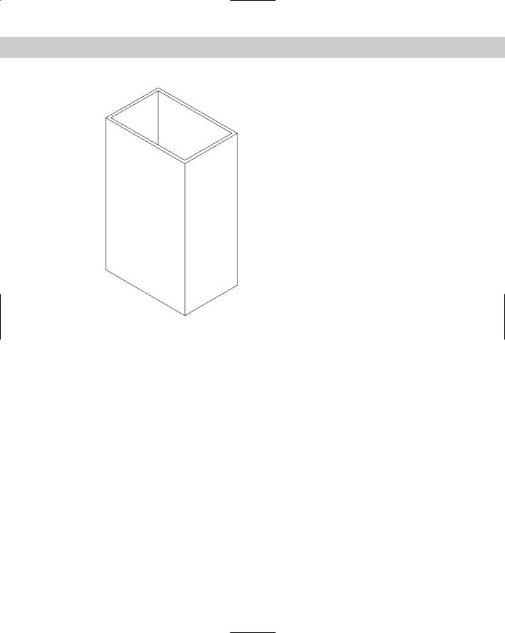
Figure 24-45: The shelled box.
Listing Solid Properties
The MASSPROP command provides information about regions and solids that is useful for engineering applications. The bounding box, for example, is an imaginary box that contains the solid. The calculations are based on the relationship of the solid to the UCS. If you rotate the solid or change the UCS, you get different results. For example, after running MASSPROP to find the center of gravity (centroid) and axes of your model, move the UCS to the centroid and then run MASSPROP again to identify the moments of inertia.
For 2D regions, the area moment of inertia that MASSPROP generates can be used to calculate bending and twisting stresses. You could generate a 2D region of a solid model using the SECTION command and then use the UCS command with the OBJECT option to set the UCS coplanar to the region. The MASSPROP command would then report the area moment of inertia.
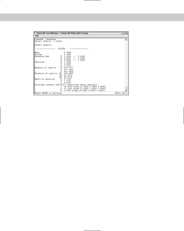
AutoCAD assumes a density of 1 for all solids. You can then apply material density multipliers on the values that get reported. Figure 24-46 shows the results of MASSPROP on a solid.
To list a solid’s properties, choose Tools Inquiry Region/Mass Properties. Select the object that you want to list. AutoCAD opens the Text Window to display the calculations. At the Write analysis to a file? [Yes/No] <N>: prompt, press Enter to accept the No default, or rightclick and choose Yes. AutoCAD prompts you for a file name and copies the data to that file.
Chapter 24 Creating Solids and Editing in 3D |
801 |
Figure 24-46: The results of the MASSPROP command.
Summary
In this chapter, you learned how to create and edit solids. You read about:
Drawing standard shapes
Creating extruded and revolved solids from 2D profiles
Using UNION, SUBTRACT, and INTERSECT to create more-complex shapes
Using the INTERFERE command to see the volume of interference between solids
Utilizing the SECTION and SLICE commands to help visualize solids
Using the special 3D editing commands MIRROR3D, 3DARRAY, and ROTATE3D
Using the TRIM, EXTEND, FILLET, and CHAMFER commands for 3D editing
Exploding into surfaces and surfaces into 2D objects
Using the SOLIDEDIT command to edit faces, edges, and bodies — solids as a whole
Calculating a number of engineering functions on solids by using the MASSPROP command
In the next chapter, I cover rendering 3D models.
|
|
|
Rendering in 3D
Although 3D drawings are more realistic than those that you create in 2D, they look very artificial — they lack realistic color,
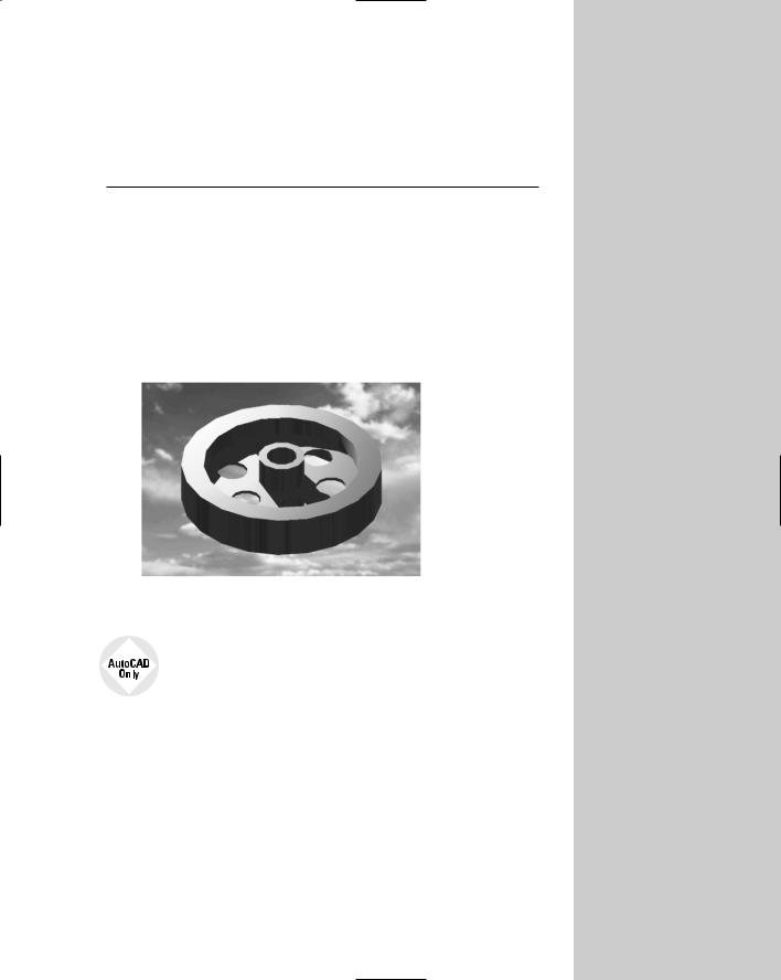
shading, and lighting, for example. Rendering enables you to display a 3D drawing more realistically. Some of the more advanced features let you create shadows, make objects transparent, add backgrounds, and map 2D images onto the surface of 3D models. You can shade and render 3D surfaces and solid models. Figure 25-1 shows a whimsical rendering that uses shadows and a background.
Figure 25-1: This cog has been rendered with shadows and a background of clouds.
AutoCAD LT does not offer any rendering features. This entire chapter applies only to AutoCAD.
Understanding Rendering
Rendering is a much more sophisticated means of visualizing a drawing than shading. AutoCAD offers three kinds of rendering: Render, Photo Real, and Photo Raytrace.
Render is AutoCAD’s original rendering tool. It provides the fewest options but the fastest results.
Photo Real creates images line by line, displays bitmaps, creates transparent materials, and makes volumetric and mapped shadows.
Photo Raytrace traces rays of light to generate reflections, refraction, and precise ray-traced shadows.
25C H A P T E R
In This Chapter
Understanding rendering
Creating
lights and scenes
Working with materials
Using backgrounds
Rendering your drawing
804 Part IV Drawing in Three Dimensions
Learning the steps
Rendering is a multi-step process. It generally requires a good deal of trial and error to get the exact results that you want. Here are the steps to render a drawing:
1.Start with trial rendering using the default settings. The results let you know what settings need to be changed.
2.Create lights. AutoCAD has four types of lights: ambient, distant, point, and spotlight. I explain lights in the “Creating Lights” section later in this chapter.
3.Create scenes. Scenes are views with lights. You can find out more about scenes in the “Creating Scenes” section later in this chapter.
4.Load materials from the materials library. You can create your own materials. Materials are surface characteristics and include color and/or pattern, ambient light, reflection, roughness, transparency, refraction, and bump map. These characteristics are explained later in this chapter in the “Working with Materials” section.
5.Attach materials to the objects in your drawing. You can attach materials by object, color, or layer.
6.Add a background or fog effect. I discuss these effects in the “Using Backgrounds” section later in this chapter.
7.Set your rendering preferences, if desired.
8.Render the drawing.
The order of the steps is flexible. For example, you can create scenes after you’ve attached materials. Also, after you render, you’ll probably see some room for improvement, so you may go back and change the lights, scenes, and/or materials.
Doing a default rendering
Doing a default rendering often helps you to decide what materials and lights you need to create your final rendering. It also reveals any problems with the models themselves. When you render, you should open the Render toolbar, which contains most of the tools you need. To do this, right-click any toolbar and choose Render.
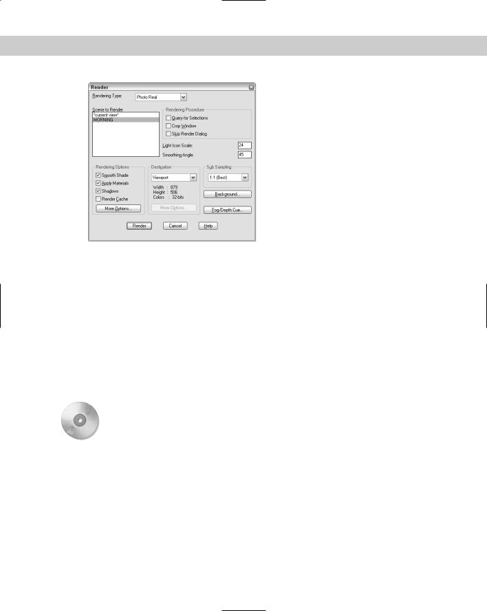
To render a drawing using the default settings, choose Render from the Render toolbar to open the Render dialog box, shown in Figure 25-2.
I cover the Render dialog box later in the chapter, but there are a couple of things that you can do when you want to get a quick rendering.
Chapter 25 Rendering in 3D 805
Figure 25-2: The Render dialog box.
You can save time by rendering only some of the objects in the view. To do this, use the Rendering Procedure section of the dialog box.
On the
CD-ROM
Check the Query for Selections check box to tell AutoCAD to display the Select objects: prompt before rendering. AutoCAD renders only the objects that you selected, instead of the entire drawing, thus saving time.
Check the Crop Window check box to tell AutoCAD to prompt you to specify a window before rendering. By rendering only a section of the drawing, you can save time.
In the Rendering Options section, check the Render Cache check box if you plan to render the same scene several times, as is often the case when you’re working on a rendering. AutoCAD saves the rendering data in a file and uses it for subsequent renderings; this saves the time needed for AutoCAD to analyze the drawing each time. Click Render to render the drawing.
The drawing used in the following exercise on creating a default rendering, ab25-a.dwg, is in the Drawings folder on the CD-ROM.
STEPS: Creating a Default Rendering
1.Open ab25-a.dwg from the CD-ROM.
2.Save the file as ab25-01.dwg in your AutoCAD Bible folder. If the Render toolbar is not displayed, right-click any toolbar and choose Render.