

- •Contents
- •Contents at a Glance
- •Acknowledgments
- •Preface
- •Is This Book for You?
- •How This Book Is Organized
- •How to Use This Book
- •Doing the Exercises
- •Conventions Used in This Book
- •What the Icons Mean
- •About the CD-ROM
- •Other Information
- •Contacting the Author
- •Foreword
- •Credits
- •About the Author
- •Summary
- •AutoCAD’s Advantages
- •Comparing AutoCAD and AutoCAD LT
- •Starting AutoCAD and AutoCAD LT
- •Creating a New Drawing
- •Using the AutoCAD and AutoCAD LT Interface
- •Creating a New Folder
- •Using the Interface
- •Saving a Drawing
- •Closing a Drawing and Exiting from AutoCAD and AutoCAD LT
- •Summary
- •Creating a New Drawing from a Template
- •Working with Templates
- •Opening a Drawing with Default Settings
- •Opening an Existing Drawing
- •Using an Existing Drawing as a Prototype
- •Saving a Drawing Under a New Name
- •Summary
- •The Command Line and Dynamic Input
- •Command Techniques
- •Of Mice and Pucks
- •Getting Help
- •Summary
- •Typing Coordinates
- •Displaying Coordinates
- •Picking Coordinates on the Screen
- •Overriding Coordinate Settings
- •Locating Points
- •Summary
- •Choosing Unit Types
- •Drawing Limits
- •Understanding Scales
- •Creating a Title Block
- •Specifying Common Setup Options
- •Customizing with the MVSETUP Command
- •Using the Setup Wizards
- •Summary
- •Using the LINE Command
- •Drawing Rectangles
- •Drawing Polygons
- •Creating Construction Lines
- •Creating Rays
- •Summary
- •Drawing Circles
- •Drawing Arcs
- •Creating Ellipses and Elliptical Arcs
- •Making Donuts
- •Placing Points
- •Summary
- •Panning
- •Using the ZOOM Command
- •Using Aerial View
- •Saving Named Views
- •Working with Tiled Viewports
- •Using Snap Rotation
- •Understanding User Coordinate Systems
- •Creating Isometric Drawings
- •Summary
- •Editing a Drawing
- •Selecting Objects
- •Summary
- •Copying and Moving Objects
- •Resizing Commands
- •Using Construction Commands
- •Creating a Revision Cloud
- •Hiding Objects with a Wipeout
- •Double-Clicking to Edit Objects
- •Grips
- •Editing with the Properties Palette
- •Selection Filters
- •Groups
- •Summary
- •Working with Layers
- •Changing Object Color, Linetype, and Lineweight
- •Working with Linetype Scales
- •Importing Layers and Linetypes from Other Drawings
- •Matching Properties
- •Summary
- •Drawing-Level Information
- •Object-Level Information
- •Measurement Commands
- •AutoCAD’s Calculator
- •Summary
- •Creating Single-Line Text
- •Understanding Text Styles
- •Creating Multiline Text
- •Creating Tables
- •Inserting Fields
- •Managing Text
- •Finding Text in Your Drawing
- •Checking Your Spelling
- •Customizing the spelling dictionary
- •Summary
- •Working with Dimensions
- •Drawing Linear Dimensions
- •Drawing Aligned Dimensions
- •Creating Baseline and Continued Dimensions
- •Dimensioning Arcs and Circles
- •Dimensioning Angles
- •Creating Ordinate Dimensions
- •Drawing Leaders
- •Using Quick Dimension
- •Editing Dimensions
- •Summary
- •Understanding Dimension Styles
- •Defining a New Dimension Style
- •Changing Dimension Styles
- •Creating Geometric Tolerances
- •Summary
- •Creating and Editing Polylines
- •Drawing and Editing Splines
- •Creating Regions
- •Creating Boundaries
- •Creating Hatches
- •Creating and Editing Multilines
- •Creating Dlines
- •Using the SKETCH Command
- •Digitizing Drawings with the TABLET Command
- •Summary
- •Preparing a Drawing for Plotting or Printing
- •Creating a Layout in Paper Space
- •Working with Plot Styles
- •Plotting a Drawing
- •Summary
- •Combining Objects into Blocks
- •Inserting Blocks and Files into Drawings
- •Managing Blocks
- •Creating and Using Dynamic Blocks
- •Using Windows Features
- •Working with Attributes
- •Summary
- •Understanding External References
- •Editing an Xref within Your Drawing
- •Controlling Xref Display
- •Managing Xrefs
- •Summary
- •Preparing for Database Connectivity
- •Connecting to Your Database
- •Linking Data to Drawing Objects
- •Creating Labels
- •Querying with the Query Editor
- •Working with Query Files
- •Summary
- •Working with 3D Coordinates
- •Using Elevation and Thickness
- •Working with the User Coordinate System
- •Summary
- •Working with the Standard Viewpoints
- •Using DDVPOINT
- •Working with the Tripod and Compass
- •Displaying a Quick Plan View
- •Shading Your Drawing
- •Using 3D Orbit
- •Using Tiled Viewports
- •Defining a Perspective View
- •Laying Out 3D Drawings
- •Summary
- •Drawing Surfaces with 3DFACE
- •Drawing Surfaces with PFACE
- •Creating Polygon Meshes with 3DMESH
- •Drawing Standard 3D Shapes
- •Drawing a Revolved Surface
- •Drawing an Extruded Surface
- •Drawing Ruled Surfaces
- •Drawing Edge Surfaces
- •Summary
- •Drawing Standard Shapes
- •Creating Extruded Solids
- •Drawing Revolved Solids
- •Creating Complex Solids
- •Sectioning and Slicing Solids
- •Using Editing Commands in 3D
- •Editing Solids
- •Listing Solid Properties
- •Summary
- •Understanding Rendering
- •Creating Lights
- •Creating Scenes
- •Working with Materials
- •Using Backgrounds
- •Doing the Final Render
- •Summary
- •Accessing Drawing Components with the DesignCenter
- •Accessing Drawing Content with Tool Palettes
- •Setting Standards for Drawings
- •Organizing Your Drawings
- •Working with Sheet Sets
- •Maintaining Security
- •Keeping Track of Referenced Files
- •Handling Errors and Crashes
- •Managing Drawings from Prior Releases
- •Summary
- •Importing and Exporting Other File Formats
- •Working with Raster Images
- •Pasting, Linking, and Embedding Objects
- •Summary
- •Sending Drawings
- •Opening Drawings from the Web
- •Creating Object Hyperlinks
- •Publishing Drawings
- •Summary
- •Working with Customizable Files
- •Creating Keyboard Shortcuts for Commands
- •Customizing Toolbars
- •Customizing Tool Palettes
- •Summary
- •Creating Macros with Script Files
- •Creating Slide Shows
- •Creating Slide Libraries
- •Summary
- •Creating Linetypes
- •Creating Hatch Patterns
- •Summary
- •Creating Shapes
- •Creating Fonts
- •Summary
- •Working with the Customization File
- •Customizing a Menu
- •Summary
- •Introducing Visual LISP
- •Getting Help in Visual LISP
- •Working with AutoLISP Expressions
- •Using AutoLISP on the Command Line
- •Creating AutoLISP Files
- •Summary
- •Creating Variables
- •Working with AutoCAD Commands
- •Working with Lists
- •Setting Conditions
- •Managing Drawing Objects
- •Getting Input from the User
- •Putting on the Finishing Touches
- •Summary
- •Understanding Local and Global Variables
- •Working with Visual LISP ActiveX Functions
- •Debugging Code
- •Summary
- •Starting to Work with VBA
- •Writing VBA Code
- •Getting User Input
- •Creating Dialog Boxes
- •Modifying Objects
- •Debugging and Trapping Errors
- •Moving to Advanced Programming
- •Summary
- •A Final Word
- •Installing AutoCAD and AutoCAD LT
- •Configuring and Using Workspaces
- •Configuring AutoCAD
- •Starting AutoCAD Your Way
- •Configuring a Plotter
- •Discovering AutoCAD and AutoCAD LT
- •Accessing Technical Support
- •Autodesk User Groups
- •Internet Resources
- •System Requirements
- •Using the CD-ROM with Microsoft Windows
- •What’s on the CD-ROM
- •Troubleshooting
- •Index

Chapter 24 Creating Solids and Editing in 3D |
789 |
Exploding 3D objects
The EXPLODE command has a particular effect that varies according to the type of 3D object. Table 24-4 lists the effects of exploding 3D objects.
|
Table 24-4: Using EXPLODE on 3D Objects |
|
|
|
|
|
Object |
Result |
|
|
|
|
Solids |
Flat surfaces become regions; curved surfaces become bodies. |
|
Bodies |
Curved surfaces become single-surface bodies; flat bodies become regions or |
|
|
curves. |
|
Polyface meshes |
3D faces. |
|
Polygon meshes |
3D faces. |
|
Polylines with thickness |
Lines. |
Note |
|
|
A body is a free-form solid. You cannot directly create a body. AutoCAD uses bodies when 3D |
||
|
models do not fit into any other object type. |
|
ACIS and stereolithography (.stl) are two file formats especially applicable to 3D models. Chapter 27 explains how to export drawings in these formats.
Editing Solids
Prior to AutoCAD 2000, direct editing of solids was very limited. You could chamfer, fillet, slice, or explode a solid. You could also use UNION, SUBTRACT, and INTERSECT. Other editing commands did not actually modify the solids. AutoCAD 2000 introduced SOLIDEDIT to directly edit solids. This command has so many options that it might as well be several commands.
SOLIDEDIT offers three major types of solid editing:
Faces: A number of options enable you to edit the faces of solids. You can extrude, move, rotate, offset, taper, delete, copy, and color (assign a color to) faces.
Edges: You can color and copy edges.
Bodies: The body options apply to solids as a whole. You can imprint, separate, shell, clean, and check solids. These options are more easily done than said.
The easiest way to use SOLIDEDIT is to open the Solids Editing toolbar and forget the labyrinthine command line.
The next three sections explain how to edit faces, edges, and bodies.
Editing faces
A face is a surface on a solid. A face can be either flat or curved. For example, a hole in a block is a face, and many of the face-editing operations work well to modify holes. Of course, you can edit an outer face of a surface as well.
790 Part IV Drawing in Three Dimensions
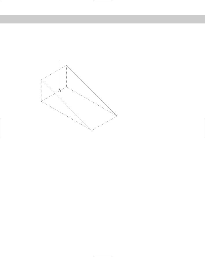
The SOLIDEDIT command supports several methods of selecting a face or faces. You’re accustomed (by now) to selecting a solid by picking one of its edges. However, an edge borders
on two faces, and when you pick an edge, AutoCAD highlights both of its adjoining faces, as shown in Figure 24-40.
Pick point on edge
Figure 24-40: When you pick an edge in the SOLIDEDIT command, AutoCAD selects its two adjoining faces.
Sometimes, picking a face on an edge works — for example, when you want to pick the entire face represented by a hole.
For other situations, to enable you to pick only one face, you can use the boundary set method, by picking within the closed boundary of a face. Generally, AutoCAD selects the front-most face. You can also use a crossing window, crossing polygon, or fence to select a face. For these three latter selection methods, you need to type c, cp, or f, respectively, and then press Enter.
Because selecting the right face can be difficult on a first try, especially for a complex solid, SOLIDEDIT offers plenty of opportunity for correction. After choosing the type of solid editing that you want, AutoCAD displays the Select faces or [Undo/Remove]: prompt. Right-click and choose Undo to undo your last selection operation. Right-click and choose Remove to select a face to remove from the selection set. (You can also press Shift and pick a face to remove it.) The prompt then includes an Add option that you can use to start adding faces again. You may have to remove and add faces more than once to get the result you want. Then press Enter to end face selection.
You may want to perform more than one operation on a face. After you complete an operation, you can right-click to open the shortcut menu and choose another operation. To exit the command, right-click and choose Exit twice.
Extruding faces
Extruding a face is like extruding a 2D object. If you’re familiar with the EXTRUDE command, you’ll feel comfortable extruding faces. To extrude a face, follow these steps:
Chapter 24 Creating Solids and Editing in 3D |
791 |
1.Choose Extrude Faces on the Solids Editing toolbar. AutoCAD starts the SOLIDEDIT command and automatically enters the first two prompts of the command for you.
2.At the Select faces or [Undo/Remove]: prompt, select the face or faces that you want to extrude, using the selection method(s) explained previously. After your first selection, the prompt adds the ALL option. When you’re done, press Enter to end face selection.
3.At the Specify height of extrusion or [Path]: prompt, type a height or right-click and choose Path to specify a path for the extrusion.
4.If you specify a height, at the Specify angle of taper for extrusion <0>: prompt, specify an angle. (As with the EXTRUDE command, a positive angle tapers inward.) If you choose the Path option, at the Select extrusion path: prompt, select an object, usually a line or arc, along which you want to extrude.
5.To extricate yourself from the command, press Enter twice.
You can also use the eXit option that appears on the command line.
AutoCAD extrudes the face. As you exit, AutoCAD performs a validation of the solid to make sure that the solid is a valid solid if the SOLIDCHECK system variable is on. By default, SOLIDCHECK is on (set to 1) and automatically checks solids when you edit them.
Moving faces
You can move a face when a solid is complex enough to have at least two separate elements — for example, a plate with a hole in it. You can then move the hole around wherever you want. Look at the mounting bracket in Figure 24-36, earlier in this chapter. You could move the hole from the left face to the right face using SOLIDEDIT. To move a face, follow these steps:
1.Choose Move Faces on the Solids Editing toolbar. AutoCAD starts the SOLIDEDIT command and automatically enters the first two prompts of the command for you.
2.Select the face or faces that you want to move, using the selection method(s) described earlier. Press Enter to end face selection.
3.At the Specify a base point or displacement: prompt, specify a base point if you want to pick two points, or specify a displacement, as you would with the MOVE command.
4.At the Specify a second point of displacement: prompt, specify a second point of displacement if you specified a base point. Otherwise, press Enter.
5.Right-click and choose Enter twice to exit the command.
If you choose a face that cannot be moved, AutoCAD displays the Modeling Operation Error: No solution for an edge message.
Offsetting faces
You can offset a face when a solid has two separate elements, such as a wall with a window cut out of it. You can then resize the window by offsetting it. Offsetting a face increases all parts of the face equally by a distance that you specify.
Use a positive offset value to increase the volume of the solid. If your face is a solid axle in the middle of a disk, for example, and you offset the axle with a positive value, the axle gets bigger. However, if your face is a hole in the middle of a disk, a positive offset value makes the hole smaller because that makes the resulting solid bigger.
792 Part IV Drawing in Three Dimensions
Use a negative offset value to decrease the volume of the solid. Using the same example, a negative offset value would make the axle smaller, but it would make the hole bigger.
To offset a face, follow these steps:
1.Choose Offset Faces from the Solids Editing toolbar. AutoCAD starts the SOLIDEDIT command and automatically enters the first two prompts of the command for you.
2.Select the face or faces that you want to offset and press Enter to end face selection.
3.At the Specify the offset distance: prompt, type a positive or negative distance. You can also pick two points to specify a positive offset.
4.Right-click and choose Enter twice to exit the command.
AutoCAD offsets the face. If there is no room for the offset, AutoCAD displays the message
Modeling Operation Error on the command line.
Deleting faces
You can delete a face of a solid. This is a great way to instantly get rid of a hole, axle, or window within a solid. You can delete faces to undo the effects of both the UNION and SUBTRACT commands. You can also remove filleted and chamfered faces. AutoCAD won’t delete every face; for example, you can’t turn a box into a tetrahedron by deleting the box’s top face. However, the capability to delete faces is a very powerful tool for editing your solids.
To delete a face or faces, choose Delete Faces from the Solids Editing toolbar. Select the face or faces and press Enter. AutoCAD deletes the face or faces that you selected. If
your face(s) can’t be deleted, you see the message Modeling Operation Error on the command line.
Rotating faces
You can rotate a face when a solid is complex enough to have at least two separate elements — for example, a box with a hole in it. The prompts for rotating are very similar to those for ROTATE3D, covered earlier in this chapter. To rotate a face, follow these steps:
1.Choose Rotate Faces on the Solids Editing toolbar. AutoCAD starts the SOLIDEDIT command and automatically enters the first two prompts of the command for you.
2.Select the face or faces that you want to rotate, using the selection method(s) described earlier. Press Enter to end face selection.
3.At the Specify an axis point or [Axis by object/View/Xaxis/Yaxis/Zaxis] <2points>: prompt, specify the first point of a rotation axis or use one of the options to define an axis of rotation.
4.If you specified a first point, at the Specify the second point on the rotation axis: prompt, specify the second point.
5.At the Specify a rotation angle or [Reference]: prompt, specify a rotation angle (the right-hand rule applies in determining the direction of rotation), or use the Reference option to specify a reference (starting) angle, and then an ending angle.
6.Right-click and choose Enter twice to exit the command.
AutoCAD rotates the face. If you choose a face that cannot be rotated, or if there isn’t room on the solid for the rotation, AutoCAD lets you know with the message Modeling Operation Error on the command line.
Chapter 24 Creating Solids and Editing in 3D |
793 |
Tapering faces
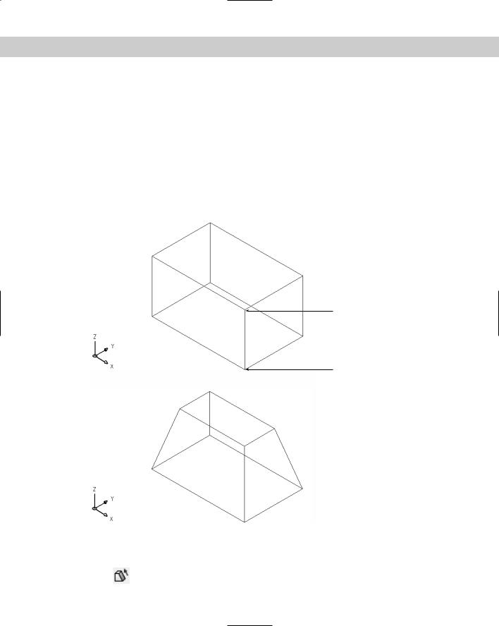
You can taper an entire simple solid, such as a box, or you can taper a face that is an element within a complex solid, such as a hole or an axle. Tapering angles the sides of the face. To determine the direction of the taper, that is, which end gets tapered, you specify a base point and a second point. The base point side of the solid is not tapered, and AutoCAD tapers the face in the direction from the base point toward the second point. You also specify the angle of the taper. A positive taper angle tapers the face inward; a hole is tapered outward. A negative taper angle tapers the face outward; a hole is tapered inward. Figure 24-41 shows a box before and after tapering at a 15-degree angle, as well as the base point and second points that were used. All of the faces except the bottom were selected.
In general, you should use small tapering angles. If the face tapers to a point before it reaches its existing height, then AutoCAD cannot complete the taper.
Second point
Base point
Figure 24-41: A box before and after tapering at a 15-degree angle.
To taper a face, follow these steps:
1.Choose Taper Faces on the Solids Editing toolbar. AutoCAD starts the SOLIDEDIT command and automatically enters the first two prompts of the command for you.
794 Part IV Drawing in Three Dimensions
2.Select the face(s) that you want to taper. Press Enter to end face selection.
3.At the Specify the base point: prompt, pick the base point for the taper direction. Object snaps are a good idea.
4.At the Specify another point along the axis of tapering: prompt, specify a second point to indicate the direction of the taper. Again, use an object snap.
5.At the Specify the taper angle: prompt, specify an angle between –90° and +90°.
6.Right-click and choose Enter twice to exit the command.
AutoCAD tapers the face. If AutoCAD can’t taper the face, you see the message Modeling Operation Error on the command line.
Copying faces
You can copy any face, including a hole. AutoCAD creates regions or bodies out of the face. You can then use the EXTRUDE command to extrude one region. However, if you copy a complex face, such as a hole that may consist of several regions, you can’t turn it back into a solid again.
To copy a face, follow these steps:
1.Choose Copy Faces from the Solids Editing toolbar. AutoCAD starts the SOLIDEDIT command and automatically enters the first two prompts of the command for you.
2.Select the face(s) that you want to copy. Press Enter to end face selection.
3.At the Specify a base point or displacement: prompt, specify a base point. Object snaps are helpful.
4.At the Specify a second point of displacement: prompt, specify a second point to indicate the direction and distance for the copy.
5.Right-click and choose Enter twice to exit the command.
AutoCAD copies the face.
Coloring faces
You can assign a color to a face of an object. You might want to color a face to make it easier to see. You can also color a face so that you can assign a material to it (you can assign materials by color) for the purpose of rendering. The color overrides the color setting for the solid’s layer.
Note When an object is assigned more than one material, priority goes to attachment by object, then by color, and finally by layer. If you attach a material to a solid by layer, and then attach a material to one of its faces (that you have colored) by color, both the solid and the face display their materials. For more information, see Chapter 25.
To color a face, follow these steps:
1.Choose Color Faces from the Solids Editing toolbar. AutoCAD starts the SOLIDEDIT command and automatically enters the first two prompts of the command for you.
2.Select the face or faces that you want to color. Press Enter to end face selection.
3.AutoCAD opens the Select Color dialog box. Choose a color and click OK.
4.Right-click and choose Enter twice to exit the command.
AutoCAD colors the face.
Chapter 24 Creating Solids and Editing in 3D |
795 |
On the |
The drawing used in the following exercise on editing solid faces, ab24-11.dwg, is in the |
CD-ROM |
Results folder on the CD-ROM. |
STEPS: Editing Solid Faces
1.Open ab24-11.dwg from the Results folder of the CD-ROM. If you did the exercise on filleting solids, you can open it from your AutoCAD Bible folder.
2.Save the file as ab24-13.dwg in your AutoCAD Bible folder.
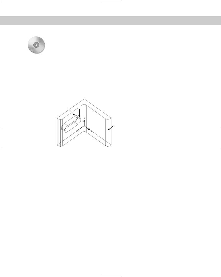
3.If the Solids Editing toolbar is not displayed, right-click any toolbar and choose Solids Editing. This is a mounting bracket, shown in Figure 24-42. Note the UCS icon, which is at 0,0,0.
2 1
3
Figure 24-42: The mounting bracket.
4.Make sure that OSNAP is on. Set a running object snap for midpoint.
5. Choose Offset Faces from the Solids Editing toolbar.
6.At the Select faces or [Undo/Remove]: prompt, select the slot in the mounting angle. Selecting the slot may require a few picks to make sure that all the parts of the slot are highlighted and to remove from selection the unwanted faces of the mounting bracket that become highlighted. (Hint: Try picking on the cross-lines that connect the front and back of the slot.) To remove a face, right-click and choose Remove. Then pick on a face’s edge. To add faces again, right-click and choose Add. After you’re done, press Enter (or right-click and choose Enter) to end face selection.
7.At the Specify the offset distance: prompt, type .1 . AutoCAD makes the slot smaller.
8.You’re still in the SOLIDEDIT command. Right-click and choose Taper. At the next prompt, select the slot and press Enter after you’re done selecting.
9.At the Specify the base point: prompt, pick the midpoint at 1.
10.At the Specify another point along the axis of tapering: prompt, pick the midpoint at 2.
11.At the Specify the taper angle: prompt, type 10 . AutoCAD tapers the slot.
796 Part IV Drawing in Three Dimensions
12.Right-click and choose Delete. At the next prompt, select the filleted face at 3. Rightclick and choose Enter. AutoCAD removes the fillet.
13.Right-click and choose Extrude. At the next prompt, select the face at 3 by picking inside the face. Right-click and choose Enter.
14.At the Specify height of extrusion or [Path]: prompt, type .2 .
15.At the Specify angle of taper for extrusion <0>: prompt, type 10 . AutoCAD extrudes the face.
16.Right-click and choose Enter twice to exit the command.
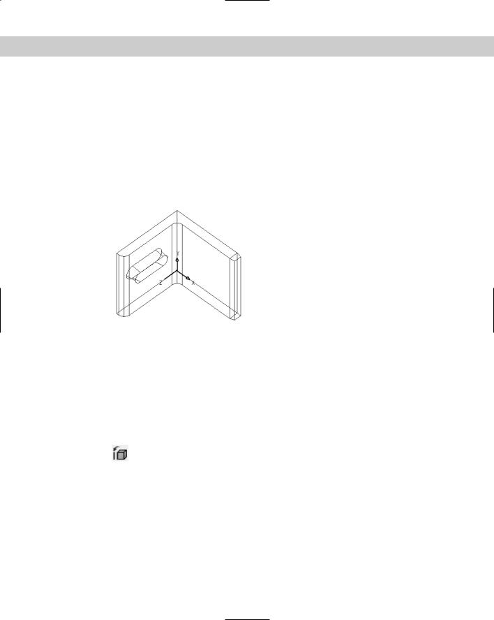
17.Save your drawing. It should look like Figure 24-43.
Figure 24-43: The edited mounting angle.
Editing edges
The two-dimensional place where two faces meet is an edge. You can perform only two editing operations on edges: you can copy them and color them.
Copying edges
When you copy an edge, you get a line, arc, circle, ellipse, or spline, depending on the shape of the solid’s edge. To copy an edge, follow these steps:
1.Choose Copy Edges from the Solids Editing toolbar. AutoCAD starts the SOLIDEDIT command and automatically enters the first two prompts of the command for you.
2.Select the edge or edges that you want to copy.
3.At the Specify a base point or displacement: prompt, specify a base point, preferably using an object snap or a displacement.
4.At the Specify a second point of displacement: prompt, specify a second point or press Enter if you specified a displacement in Step 2.
5.Right-click and choose Enter twice to exit the command.
AutoCAD copies the edge or edges.
Chapter 24 Creating Solids and Editing in 3D |
797 |
Coloring edges
You can color an edge to make it more visible. The color overrides the color setting for the solid’s layer. To color an edge, follow these steps:
1.Choose Color Edges from the Solids Editing toolbar. AutoCAD starts the SOLIDEDIT command and automatically enters the first two prompts of the command for you.
2.Select the edge or edges that you want to color. Press Enter to end edge selection.
3.AutoCAD opens the Select Color dialog box. Choose the color you want and click OK.
4.Right-click and choose Enter twice to exit the command.
AutoCAD colors the edge.
Editing bodies
Several of the SOLIDEDIT options apply to solids as a whole. The operations available are imprinting, cleaning, separating, shelling, and checking. Each operation is discussed in the following sections.
Imprinting solids
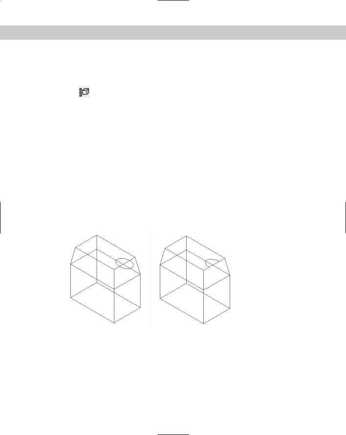
You can imprint an arc, circle, line, 2D polyline or 3D polyline, ellipse, spline, region, body, or 3D solid on a solid. The object that you’re imprinting must intersect a face on the solid. The shape made by the intersection of the object is left on the solid, as if you put ink on the edges of the object and stamped it on the solid. Figure 24-44 shows an example of imprinting.
Figure 24-44: The ellipse was drawn on the top of the solid. After imprinting and deleting the ellipse, the shape of half of the ellipse remains on the solid.
To imprint a solid, follow these steps:
1.First create one of the stampable objects previously listed so that it intersects with a solid. If you draw in top view, check in an isometric view to make sure that the intersection is where you want it.
798 Part IV Drawing in Three Dimensions
2.Choose Imprint from the Solids Editing toolbar. AutoCAD starts the SOLIDEDIT command and automatically enters the first two prompts of the command for you.
3.At the Select a 3D solid: prompt, select a solid. You can select only one.
4.At the Select an object to imprint: prompt, select the object that you want to imprint.
5.At the Delete the source object [Yes/No] <N>: prompt, type y or press Enter to indicate No.
6.AutoCAD repeats the Select an object to imprint: prompt. You can continue the command in the same way or press Enter if you’re done.
7.Right-click and choose Enter twice to exit the command.
AutoCAD imprints the solid. If you didn’t delete the source object, you’ll need to move it to see the result.
Cleaning solids
After all the editing, you can end up with some pretty strange solids. Cleaning solids removes imprints as well as adjacent faces that share the same surface.
To clean a solid, choose Clean from the Solids Editing toolbar. At the Select a 3D solid: prompt, select a solid. AutoCAD cleans it.
Separating solids
You can separate a solid that is made up of more than one completely separate section. You would generally create such a solid from separate, nontouching solids, using the UNION command. The Separate option undoes the effect of the UNION command so that the solids become separate again. You can compare this operation to grouping and ungrouping objects (see Chapter 18).
To separate a solid, choose Separate from the Solids Editing toolbar. At the Select a 3D solid: prompt, select the solid by picking any of its sections. AutoCAD separates the
solids.
If your solid sections are even touching, you get one of the funnier AutoCAD messages: The selected solid does not have multiple lumps.
Shelling solids
When you shell a solid, you hollow out its inside, leaving a thin wall. Think of making a drinking glass from a truncated cone (or tapered cylinder) or a room from a solid box. Shelling is a common process in high-end 3D modeling programs. To shell a solid, follow these steps:
1.Choose Shell from the Solids Editing toolbar. AutoCAD starts the SOLIDEDIT command and automatically enters the first two prompts of the command for you.
2.Select a solid.
3.At the Remove faces or [Undo/Add/ALL]: prompt, remove any face or faces that you don’t want to shell. For example, if you’re making a drinking glass from a truncated cone, you want to remove the larger circular face (the one you would drink out of) so that it will remain open. Otherwise, you end up with an enclosed solid that has a hollow
Chapter 24 Creating Solids and Editing in 3D |
799 |
interior. After you finish removing faces, press Enter. (The command line confirms 1 face found, 1 removed, but there is no obvious confirmation that AutoCAD has removed the correct face.)
4.At the Enter the shell offset distance: prompt, type the width of the wall that you want to create. A positive value creates a shell to the inside of the current solid. A negative value creates a shell to the outside of the current solid.
5.Right-click and choose Enter twice to exit the command.
AutoCAD shells the solid.
Checking solids
Checking ensures that your solid is a valid 3D solid object so that you can edit it without getting ACIS failure error messages. This might be a useful feature to put into an AutoLISP or VBA program, to make sure that it doesn’t fail because of invalid solids.
To check a solid, choose Check from the Solids Editing toolbar. At the Select a 3D solid: prompt, select a solid. Usually, AutoCAD replies with the message: This object is a
valid ShapeManager solid.
On the |
The drawing used in the following exercise on editing solid bodies, ab24-j.dwg, is in the |
CD-ROM |
Drawings folder on the CD-ROM. |
STEPS: Editing Solid Bodies
1.Open ab24-j.dwg from the CD-ROM.
2.Save the file as ab24-14.dwg in your AutoCAD Bible folder. This is a simple solid box with an ellipse drawn on part of its top face.
3.Choose Imprint from the Solids Editing toolbar. Follow the prompts:
Select a 3D solid: Select the box.
Select an object to imprint: Select the ellipse. Delete the source object [Yes/No] <N>: y . Select an object to imprint: Right-click.
4.Right-click and choose Clean. At the Select a 3D solid: prompt, select the box.
5.Right-click and choose Shell. Follow the prompts:
Select a 3D Solid: Select the box.
Remove faces or [Undo/Add/ALL]: Pick anywhere inside the top face.
Remove faces or [Undo/Add/ALL]: Right-click and choose Enter. Enter the shell offset distance: .1
6.Press Enter twice to exit the command.
7.Choose View Hide. You can now see the result of the shell operation.
8.Save your drawing. It should look like Figure 24-45.