

- •Contents
- •Contents at a Glance
- •Acknowledgments
- •Preface
- •Is This Book for You?
- •How This Book Is Organized
- •How to Use This Book
- •Doing the Exercises
- •Conventions Used in This Book
- •What the Icons Mean
- •About the CD-ROM
- •Other Information
- •Contacting the Author
- •Foreword
- •Credits
- •About the Author
- •Summary
- •AutoCAD’s Advantages
- •Comparing AutoCAD and AutoCAD LT
- •Starting AutoCAD and AutoCAD LT
- •Creating a New Drawing
- •Using the AutoCAD and AutoCAD LT Interface
- •Creating a New Folder
- •Using the Interface
- •Saving a Drawing
- •Closing a Drawing and Exiting from AutoCAD and AutoCAD LT
- •Summary
- •Creating a New Drawing from a Template
- •Working with Templates
- •Opening a Drawing with Default Settings
- •Opening an Existing Drawing
- •Using an Existing Drawing as a Prototype
- •Saving a Drawing Under a New Name
- •Summary
- •The Command Line and Dynamic Input
- •Command Techniques
- •Of Mice and Pucks
- •Getting Help
- •Summary
- •Typing Coordinates
- •Displaying Coordinates
- •Picking Coordinates on the Screen
- •Overriding Coordinate Settings
- •Locating Points
- •Summary
- •Choosing Unit Types
- •Drawing Limits
- •Understanding Scales
- •Creating a Title Block
- •Specifying Common Setup Options
- •Customizing with the MVSETUP Command
- •Using the Setup Wizards
- •Summary
- •Using the LINE Command
- •Drawing Rectangles
- •Drawing Polygons
- •Creating Construction Lines
- •Creating Rays
- •Summary
- •Drawing Circles
- •Drawing Arcs
- •Creating Ellipses and Elliptical Arcs
- •Making Donuts
- •Placing Points
- •Summary
- •Panning
- •Using the ZOOM Command
- •Using Aerial View
- •Saving Named Views
- •Working with Tiled Viewports
- •Using Snap Rotation
- •Understanding User Coordinate Systems
- •Creating Isometric Drawings
- •Summary
- •Editing a Drawing
- •Selecting Objects
- •Summary
- •Copying and Moving Objects
- •Resizing Commands
- •Using Construction Commands
- •Creating a Revision Cloud
- •Hiding Objects with a Wipeout
- •Double-Clicking to Edit Objects
- •Grips
- •Editing with the Properties Palette
- •Selection Filters
- •Groups
- •Summary
- •Working with Layers
- •Changing Object Color, Linetype, and Lineweight
- •Working with Linetype Scales
- •Importing Layers and Linetypes from Other Drawings
- •Matching Properties
- •Summary
- •Drawing-Level Information
- •Object-Level Information
- •Measurement Commands
- •AutoCAD’s Calculator
- •Summary
- •Creating Single-Line Text
- •Understanding Text Styles
- •Creating Multiline Text
- •Creating Tables
- •Inserting Fields
- •Managing Text
- •Finding Text in Your Drawing
- •Checking Your Spelling
- •Customizing the spelling dictionary
- •Summary
- •Working with Dimensions
- •Drawing Linear Dimensions
- •Drawing Aligned Dimensions
- •Creating Baseline and Continued Dimensions
- •Dimensioning Arcs and Circles
- •Dimensioning Angles
- •Creating Ordinate Dimensions
- •Drawing Leaders
- •Using Quick Dimension
- •Editing Dimensions
- •Summary
- •Understanding Dimension Styles
- •Defining a New Dimension Style
- •Changing Dimension Styles
- •Creating Geometric Tolerances
- •Summary
- •Creating and Editing Polylines
- •Drawing and Editing Splines
- •Creating Regions
- •Creating Boundaries
- •Creating Hatches
- •Creating and Editing Multilines
- •Creating Dlines
- •Using the SKETCH Command
- •Digitizing Drawings with the TABLET Command
- •Summary
- •Preparing a Drawing for Plotting or Printing
- •Creating a Layout in Paper Space
- •Working with Plot Styles
- •Plotting a Drawing
- •Summary
- •Combining Objects into Blocks
- •Inserting Blocks and Files into Drawings
- •Managing Blocks
- •Creating and Using Dynamic Blocks
- •Using Windows Features
- •Working with Attributes
- •Summary
- •Understanding External References
- •Editing an Xref within Your Drawing
- •Controlling Xref Display
- •Managing Xrefs
- •Summary
- •Preparing for Database Connectivity
- •Connecting to Your Database
- •Linking Data to Drawing Objects
- •Creating Labels
- •Querying with the Query Editor
- •Working with Query Files
- •Summary
- •Working with 3D Coordinates
- •Using Elevation and Thickness
- •Working with the User Coordinate System
- •Summary
- •Working with the Standard Viewpoints
- •Using DDVPOINT
- •Working with the Tripod and Compass
- •Displaying a Quick Plan View
- •Shading Your Drawing
- •Using 3D Orbit
- •Using Tiled Viewports
- •Defining a Perspective View
- •Laying Out 3D Drawings
- •Summary
- •Drawing Surfaces with 3DFACE
- •Drawing Surfaces with PFACE
- •Creating Polygon Meshes with 3DMESH
- •Drawing Standard 3D Shapes
- •Drawing a Revolved Surface
- •Drawing an Extruded Surface
- •Drawing Ruled Surfaces
- •Drawing Edge Surfaces
- •Summary
- •Drawing Standard Shapes
- •Creating Extruded Solids
- •Drawing Revolved Solids
- •Creating Complex Solids
- •Sectioning and Slicing Solids
- •Using Editing Commands in 3D
- •Editing Solids
- •Listing Solid Properties
- •Summary
- •Understanding Rendering
- •Creating Lights
- •Creating Scenes
- •Working with Materials
- •Using Backgrounds
- •Doing the Final Render
- •Summary
- •Accessing Drawing Components with the DesignCenter
- •Accessing Drawing Content with Tool Palettes
- •Setting Standards for Drawings
- •Organizing Your Drawings
- •Working with Sheet Sets
- •Maintaining Security
- •Keeping Track of Referenced Files
- •Handling Errors and Crashes
- •Managing Drawings from Prior Releases
- •Summary
- •Importing and Exporting Other File Formats
- •Working with Raster Images
- •Pasting, Linking, and Embedding Objects
- •Summary
- •Sending Drawings
- •Opening Drawings from the Web
- •Creating Object Hyperlinks
- •Publishing Drawings
- •Summary
- •Working with Customizable Files
- •Creating Keyboard Shortcuts for Commands
- •Customizing Toolbars
- •Customizing Tool Palettes
- •Summary
- •Creating Macros with Script Files
- •Creating Slide Shows
- •Creating Slide Libraries
- •Summary
- •Creating Linetypes
- •Creating Hatch Patterns
- •Summary
- •Creating Shapes
- •Creating Fonts
- •Summary
- •Working with the Customization File
- •Customizing a Menu
- •Summary
- •Introducing Visual LISP
- •Getting Help in Visual LISP
- •Working with AutoLISP Expressions
- •Using AutoLISP on the Command Line
- •Creating AutoLISP Files
- •Summary
- •Creating Variables
- •Working with AutoCAD Commands
- •Working with Lists
- •Setting Conditions
- •Managing Drawing Objects
- •Getting Input from the User
- •Putting on the Finishing Touches
- •Summary
- •Understanding Local and Global Variables
- •Working with Visual LISP ActiveX Functions
- •Debugging Code
- •Summary
- •Starting to Work with VBA
- •Writing VBA Code
- •Getting User Input
- •Creating Dialog Boxes
- •Modifying Objects
- •Debugging and Trapping Errors
- •Moving to Advanced Programming
- •Summary
- •A Final Word
- •Installing AutoCAD and AutoCAD LT
- •Configuring and Using Workspaces
- •Configuring AutoCAD
- •Starting AutoCAD Your Way
- •Configuring a Plotter
- •Discovering AutoCAD and AutoCAD LT
- •Accessing Technical Support
- •Autodesk User Groups
- •Internet Resources
- •System Requirements
- •Using the CD-ROM with Microsoft Windows
- •What’s on the CD-ROM
- •Troubleshooting
- •Index
Chapter 24 Creating Solids and Editing in 3D |
761 |
1.First determine the positive direction of the axis. If you specify start and endpoints, the positive axis direction goes from the start point to the endpoint. If you pick an object, the positive axis direction goes from the pick point to the other endpoint. If you choose the X or Y axis, the positive direction is obvious.
2.Point your right thumb in the positive direction of the axis.
3.Look at the curl of your fingers on that hand. That’s the positive direction of rotation.
Creating Complex Solids
To create realistic objects, you usually need to edit the simple shapes that I have discussed in this chapter. You can create complex solids by adding them, subtracting them, or intersecting them. These processes are called Boolean operations, which in this context means using logical functions, such as addition or subtraction, on objects.
|
Adding solids |
|
You use the UNION command to add two solids together, making one solid. If the solids are |
|
touching, you get a new, unified solid. If the solids are not touching, but rather completely |
|
separate, using UNION is similar to grouping, because you select them as one object. |
Tip |
You can also use the UNION command with 2D regions, either for 2D drawings or as a |
|
basis for a 3D model. |
|
Figure 24-13 shows the union of two solids after you use the HIDE command. |
|
To start the UNION command, choose Modify Solids Editing Union. (You can also |
|
open the Solids Editing toolbar and choose Union.) At the Select objects: prompt, |
|
select the objects that you want to unite. |
Figure 24-13: The results of UNION on two solids — shown after using the HIDE command.
762 Part IV Drawing in Three Dimensions
Caution |
When you create complex solids, the original solids are not retained. Setting the DELOBJ system |
|
variable to 0 (zero) doesn’t work because the original solids have been changed. If you want, |
|
you can copy the original objects to another location in the drawing in case you need to use |
|
them again. You can also use UNDO if the result is not what you expected. |
Subtracting solids
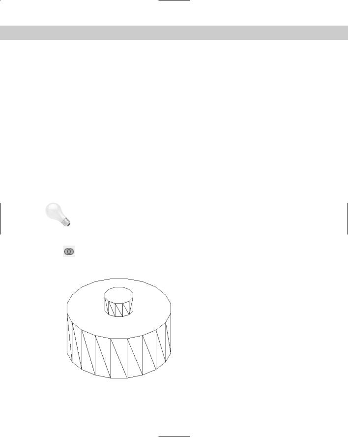
You use the SUBTRACT command to subtract one solid from another. This command is most commonly used to create holes. Figure 24-14 shows the result of subtracting a small cylinder from a larger one and then using the HIDE command.
Figure 24-14: You can create holes using the SUBTRACT command.
To subtract solids, follow these steps:
1.Choose Modify Solids Editing Subtract or choose Subtract from the Solids Editing toolbar.
2.At the following prompt, choose the solid (or region) that you want to subtract from (the one you want to keep):
Select solids and regions to subtract from...
Select objects:
3.At the following prompt, choose the solid (or region) that you want to subtract (the one you want to get rid of):
Select solids and regions to subtract...
Select objects:
Creating a solid from the intersection of two solids
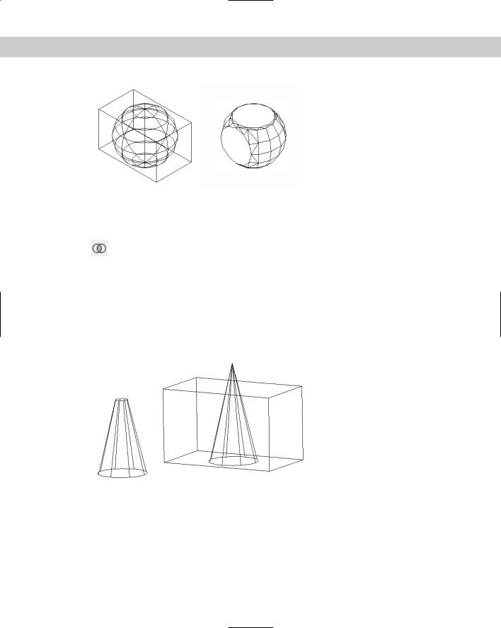
You can also create a solid from the volume that two solids have in common. This volume is called their intersection. Figure 24-15 shows two solids before and after using the INTERSECT command. The solid on the right is shown after using the HIDE command.
Chapter 24 Creating Solids and Editing in 3D |
763 |
Figure 24-15: A box and a sphere before and after using the INTERSECT command.
As you can see, you can create some very unusual models this way.
To use the INTERSECT command, choose Modify Solids Editing Intersect or choose Intersect from the Solids Editing toolbar. Just select the objects in any order. AutoCAD
creates the new solid.
Creating a new solid using INTERFERE
INTERFERE is similar to INTERSECT except that the original solids remain. AutoCAD creates a third solid from the volume that the two solids have in common. The INTERFERE command can also be used to highlight the common volume of several pairs of solids. Figure 24-16 shows a solid that was created using INTERFERE, after it was moved away from its original location. As you can see, the original solids remain intact.
Figure 24-16: When you use INTERFERE, the original solids remain intact.
INTERFERE is useful when you have a number of interfering solids. This command enables you to divide the selection set of solids into two sets so that you can compare one against the other. For example, you can compare a box with three other solids by putting the box in one set and the other three solids in the other set. INTERFERE highlights each pair of interfering solids in turn so that you can easily visualize your drawing.
764 Part IV Drawing in Three Dimensions
Tip |
You can use INTERFERE for troubleshooting and visualizing a complex drawing. For example, |
|
you can use INTERFERE to determine which solids need to be subtracted from other solids. The |
|
new objects are created on the current layer. You can change the current layer before using |
|
INTERFERE to help you more clearly distinguish the new solid that you create. |
To use INTERFERE, follow these steps:
1. Choose Interference from the Solids toolbar.
2.At the Select first set of solids: prompt, select objects. If you want to compare only two objects, you can put them both in the first set. Otherwise, select solids for the first set and press Enter to end object selection.
3.At the Select second set of solids: prompt, select the second set of objects and press Enter to end object selection. If you don’t want a second set, press Enter. AutoCAD displays the number of solids and sets how many interfering pairs it finds.
4.At the Create interference solids? [Yes/No] <N>: prompt, press Enter if you don’t want to create a new solid. Right-click and choose Yes if you do.
5.If you’re testing more than two solids, you see the Highlight pairs of interfering solids? [Yes/No] <N>: prompt. Press Enter if you don’t need to see each pair of interfering solids highlighted. Right-click and choose Yes if you want AutoCAD to highlight the pairs. If you choose Yes, AutoCAD highlights the first pair of solids that interfere.
6.At the Enter an option [Next pair/eXit] <Next>: prompt — which appears only if there is more than one pair — press Enter to see the next pair highlighted. Continue to press Enter to cycle through the interfering pairs. Right-click and choose Exit to exit the command.
On the |
The drawing used in the following exercise on creating complex solids, ab24-b.dwg, is in |
CD-ROM |
the Drawings folder on the CD-ROM. |
STEPS: Creating Complex Solids
1.Open ab-24-b.dwg from the CD-ROM.
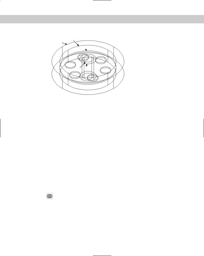
2.Save the file as ab24-03.dwg in your AutoCAD Bible folder. Make sure that OSNAP is on. Set running object snaps for endpoint, midpoint, and center. This drawing is measured in millimeters. The solids have been created by drawing circles, using EXTRUDE, and moving the solids to the proper Z coordinate. The result is shown in Figure 24-17.
3.Display the Solids Editing toolbar by right-clicking any toolbar and choosing Solids Editing.
4.To create the six holes arrayed around the center plate, choose Subtract from the Solids Editing toolbar. Follow the prompts:
Select solids and regions to subtract from...
Select objects: Select the central plate at 1 in Figure 24-17.
Select objects: Right-click.
Select solids and regions to subtract...
Select objects: Select the six circles arrayed around the plate. Right-click to end selection.
Chapter 24 Creating Solids and Editing in 3D |
765 |
5
4
1
3 2
2
Figure 24-17: These solids are the basis for the model.
5.To create the central tube, choose Subtract from the Solids Editing toolbar. Follow the prompts:
Select solids and regions to subtract from...
Select objects: Select the outer tube at 2.
Select objects: Right-click.
Select solids and regions to subtract...
Select objects: Select the inner tube at 3. Right-click to end selection.
6.To “carve out” the central disk, choose Subtract from the Solids Editing toolbar. Follow the prompts:
Select solids and regions to subtract from...
Select objects: Select the outer circle at 4.
Select objects: Right-click.
Select solids and regions to subtract...
Select objects: Select the inner circle at 5. Right-click to end selection.
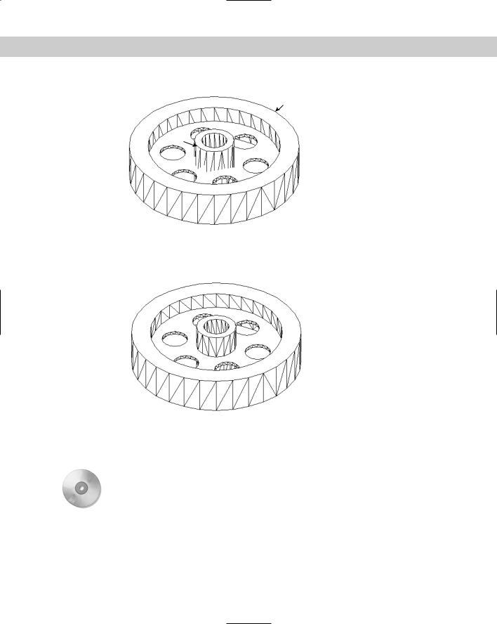
7.Use the HIDE command to see the result. This enables you to check the effects of the subtraction operations. Your drawing should look like Figure 24-18.
8.Choose Union from the Solids Editing toolbar. Select the three solids at 1, 2, and 3 in Figure 24-18 and right-click to end selection.
9.Use the HIDE command again to see the result.
10.Save your drawing. It should look like Figure 24-19. If you’re continuing on to the next exercise, leave it open.
766 Part IV Drawing in Three Dimensions
1
3
 2
2
Figure 24-18: The result of three subtraction operations.
|
Figure 24-19: The final model after using the UNION |
|
command to create one object from three. |
On the |
3D Kitchen Plus is a library of 3D kitchen cabinets. You can choose from several models. |
CD-ROM |
|