

- •Contents
- •Contents at a Glance
- •Acknowledgments
- •Preface
- •Is This Book for You?
- •How This Book Is Organized
- •How to Use This Book
- •Doing the Exercises
- •Conventions Used in This Book
- •What the Icons Mean
- •About the CD-ROM
- •Other Information
- •Contacting the Author
- •Foreword
- •Credits
- •About the Author
- •Summary
- •AutoCAD’s Advantages
- •Comparing AutoCAD and AutoCAD LT
- •Starting AutoCAD and AutoCAD LT
- •Creating a New Drawing
- •Using the AutoCAD and AutoCAD LT Interface
- •Creating a New Folder
- •Using the Interface
- •Saving a Drawing
- •Closing a Drawing and Exiting from AutoCAD and AutoCAD LT
- •Summary
- •Creating a New Drawing from a Template
- •Working with Templates
- •Opening a Drawing with Default Settings
- •Opening an Existing Drawing
- •Using an Existing Drawing as a Prototype
- •Saving a Drawing Under a New Name
- •Summary
- •The Command Line and Dynamic Input
- •Command Techniques
- •Of Mice and Pucks
- •Getting Help
- •Summary
- •Typing Coordinates
- •Displaying Coordinates
- •Picking Coordinates on the Screen
- •Overriding Coordinate Settings
- •Locating Points
- •Summary
- •Choosing Unit Types
- •Drawing Limits
- •Understanding Scales
- •Creating a Title Block
- •Specifying Common Setup Options
- •Customizing with the MVSETUP Command
- •Using the Setup Wizards
- •Summary
- •Using the LINE Command
- •Drawing Rectangles
- •Drawing Polygons
- •Creating Construction Lines
- •Creating Rays
- •Summary
- •Drawing Circles
- •Drawing Arcs
- •Creating Ellipses and Elliptical Arcs
- •Making Donuts
- •Placing Points
- •Summary
- •Panning
- •Using the ZOOM Command
- •Using Aerial View
- •Saving Named Views
- •Working with Tiled Viewports
- •Using Snap Rotation
- •Understanding User Coordinate Systems
- •Creating Isometric Drawings
- •Summary
- •Editing a Drawing
- •Selecting Objects
- •Summary
- •Copying and Moving Objects
- •Resizing Commands
- •Using Construction Commands
- •Creating a Revision Cloud
- •Hiding Objects with a Wipeout
- •Double-Clicking to Edit Objects
- •Grips
- •Editing with the Properties Palette
- •Selection Filters
- •Groups
- •Summary
- •Working with Layers
- •Changing Object Color, Linetype, and Lineweight
- •Working with Linetype Scales
- •Importing Layers and Linetypes from Other Drawings
- •Matching Properties
- •Summary
- •Drawing-Level Information
- •Object-Level Information
- •Measurement Commands
- •AutoCAD’s Calculator
- •Summary
- •Creating Single-Line Text
- •Understanding Text Styles
- •Creating Multiline Text
- •Creating Tables
- •Inserting Fields
- •Managing Text
- •Finding Text in Your Drawing
- •Checking Your Spelling
- •Customizing the spelling dictionary
- •Summary
- •Working with Dimensions
- •Drawing Linear Dimensions
- •Drawing Aligned Dimensions
- •Creating Baseline and Continued Dimensions
- •Dimensioning Arcs and Circles
- •Dimensioning Angles
- •Creating Ordinate Dimensions
- •Drawing Leaders
- •Using Quick Dimension
- •Editing Dimensions
- •Summary
- •Understanding Dimension Styles
- •Defining a New Dimension Style
- •Changing Dimension Styles
- •Creating Geometric Tolerances
- •Summary
- •Creating and Editing Polylines
- •Drawing and Editing Splines
- •Creating Regions
- •Creating Boundaries
- •Creating Hatches
- •Creating and Editing Multilines
- •Creating Dlines
- •Using the SKETCH Command
- •Digitizing Drawings with the TABLET Command
- •Summary
- •Preparing a Drawing for Plotting or Printing
- •Creating a Layout in Paper Space
- •Working with Plot Styles
- •Plotting a Drawing
- •Summary
- •Combining Objects into Blocks
- •Inserting Blocks and Files into Drawings
- •Managing Blocks
- •Creating and Using Dynamic Blocks
- •Using Windows Features
- •Working with Attributes
- •Summary
- •Understanding External References
- •Editing an Xref within Your Drawing
- •Controlling Xref Display
- •Managing Xrefs
- •Summary
- •Preparing for Database Connectivity
- •Connecting to Your Database
- •Linking Data to Drawing Objects
- •Creating Labels
- •Querying with the Query Editor
- •Working with Query Files
- •Summary
- •Working with 3D Coordinates
- •Using Elevation and Thickness
- •Working with the User Coordinate System
- •Summary
- •Working with the Standard Viewpoints
- •Using DDVPOINT
- •Working with the Tripod and Compass
- •Displaying a Quick Plan View
- •Shading Your Drawing
- •Using 3D Orbit
- •Using Tiled Viewports
- •Defining a Perspective View
- •Laying Out 3D Drawings
- •Summary
- •Drawing Surfaces with 3DFACE
- •Drawing Surfaces with PFACE
- •Creating Polygon Meshes with 3DMESH
- •Drawing Standard 3D Shapes
- •Drawing a Revolved Surface
- •Drawing an Extruded Surface
- •Drawing Ruled Surfaces
- •Drawing Edge Surfaces
- •Summary
- •Drawing Standard Shapes
- •Creating Extruded Solids
- •Drawing Revolved Solids
- •Creating Complex Solids
- •Sectioning and Slicing Solids
- •Using Editing Commands in 3D
- •Editing Solids
- •Listing Solid Properties
- •Summary
- •Understanding Rendering
- •Creating Lights
- •Creating Scenes
- •Working with Materials
- •Using Backgrounds
- •Doing the Final Render
- •Summary
- •Accessing Drawing Components with the DesignCenter
- •Accessing Drawing Content with Tool Palettes
- •Setting Standards for Drawings
- •Organizing Your Drawings
- •Working with Sheet Sets
- •Maintaining Security
- •Keeping Track of Referenced Files
- •Handling Errors and Crashes
- •Managing Drawings from Prior Releases
- •Summary
- •Importing and Exporting Other File Formats
- •Working with Raster Images
- •Pasting, Linking, and Embedding Objects
- •Summary
- •Sending Drawings
- •Opening Drawings from the Web
- •Creating Object Hyperlinks
- •Publishing Drawings
- •Summary
- •Working with Customizable Files
- •Creating Keyboard Shortcuts for Commands
- •Customizing Toolbars
- •Customizing Tool Palettes
- •Summary
- •Creating Macros with Script Files
- •Creating Slide Shows
- •Creating Slide Libraries
- •Summary
- •Creating Linetypes
- •Creating Hatch Patterns
- •Summary
- •Creating Shapes
- •Creating Fonts
- •Summary
- •Working with the Customization File
- •Customizing a Menu
- •Summary
- •Introducing Visual LISP
- •Getting Help in Visual LISP
- •Working with AutoLISP Expressions
- •Using AutoLISP on the Command Line
- •Creating AutoLISP Files
- •Summary
- •Creating Variables
- •Working with AutoCAD Commands
- •Working with Lists
- •Setting Conditions
- •Managing Drawing Objects
- •Getting Input from the User
- •Putting on the Finishing Touches
- •Summary
- •Understanding Local and Global Variables
- •Working with Visual LISP ActiveX Functions
- •Debugging Code
- •Summary
- •Starting to Work with VBA
- •Writing VBA Code
- •Getting User Input
- •Creating Dialog Boxes
- •Modifying Objects
- •Debugging and Trapping Errors
- •Moving to Advanced Programming
- •Summary
- •A Final Word
- •Installing AutoCAD and AutoCAD LT
- •Configuring and Using Workspaces
- •Configuring AutoCAD
- •Starting AutoCAD Your Way
- •Configuring a Plotter
- •Discovering AutoCAD and AutoCAD LT
- •Accessing Technical Support
- •Autodesk User Groups
- •Internet Resources
- •System Requirements
- •Using the CD-ROM with Microsoft Windows
- •What’s on the CD-ROM
- •Troubleshooting
- •Index
Chapter 24 Creating Solids and Editing in 3D |
757 |
Creating Extruded Solids
The EXTRUDE command creates solids from closed 2D objects. The result is similar to adding thickness to a 2D object (discussed in Chapter 21) or using the TABSURF command (see Chapter 23), except that you get a solid instead of a surface.
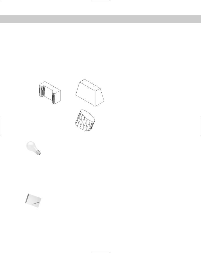
You can extrude closed 2D polylines, circles, ellipses, closed splines, donuts, and regions. You can use the REGION command to create one object from several objects for this purpose. You can select several objects and extrude them at one time. Figure 24-9 shows several extruded solids.
|
Figure 24-9: Some extruded solids. |
Tip |
The DELOBJ system variable determines whether objects used by the EXTRUDE command to |
|
make other objects are retained. By default, they’re deleted. Therefore, when you use a 2D |
|
object to make a solid, the 2D object is deleted. If you make a mistake during extrusion and |
|
notice it later — after it’s impractical to undo several commands that you want to keep — when |
|
you erase the solid, you do not have a 2D object to use to re-create the solid. (You can put such |
|
objects on a layer that can be turned off, in case you need them again.) Set DELOBJ to 0 (zero) |
|
to keep objects used to create other objects. On the other hand, if you’re sure about what you’re |
|
doing, keeping DELOBJ at 1 avoids having to erase unwanted 2D objects in your drawing. |
|
When you extrude an object, by default you extrude it perpendicular to the object. However, |
|
you can also taper the extrusion, as in the extruded rectangle in Figure 24-9. The angle is |
|
measured so that a positive angle tapers the object inward. A negative angle tapers the object |
|
outward so it gets wider as it extrudes. |
Note |
Don’t taper the object too much. If the taper angle results in the object coming to a point |
|
before its full height, AutoCAD cannot create the solid. |
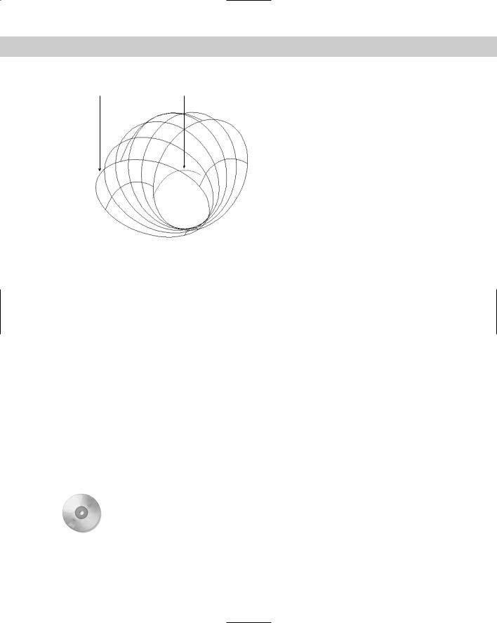
You can extrude the object along a path. A path can be a line, circle, arc, ellipse, elliptical arc, polyline, or a spline. The path object must be in a different plane than the original object. Figure 24-10 shows a circle extruded along an arc.
758 Part IV Drawing in Three Dimensions
Original circle Arc used as path for extrusion
Figure 24-10: A circle extruded along an arc.
Not all paths are suitable for extruding objects. In the following situations, the extrusion may not work. The path should not be:
Too close to the original object’s plane
Too complex
Too tightly curved or bent for the size of the original object Here are the steps for creating an extruded solid:
1.Draw the object that you want to extrude. If you want to extrude along a path, draw the path object.
2. Choose Extrude from the Solids toolbar.
3.Select the object or objects to extrude.
4.At the Specify height of extrusion or [Path]: prompt, specify the height of the extrusion or use the Path option to extrude along a path object.
If you specified a height, at the Specify angle of taper for extrusion <0>: prompt, press Enter to extrude with no taper angle or specify a taper angle.
If you chose the Path option, at the Select extrusion path or [Taper angle]: prompt, select the path object.
On the |
The drawing used in the following exercise on creating extruded solids, ab24-a.dwg, is in |
CD-ROM |
the Drawings folder on the CD-ROM. |
Chapter 24 Creating Solids and Editing in 3D |
759 |
STEPS: Creating Extruded Solids
1.Open ab24-a.dwg from the CD-ROM.
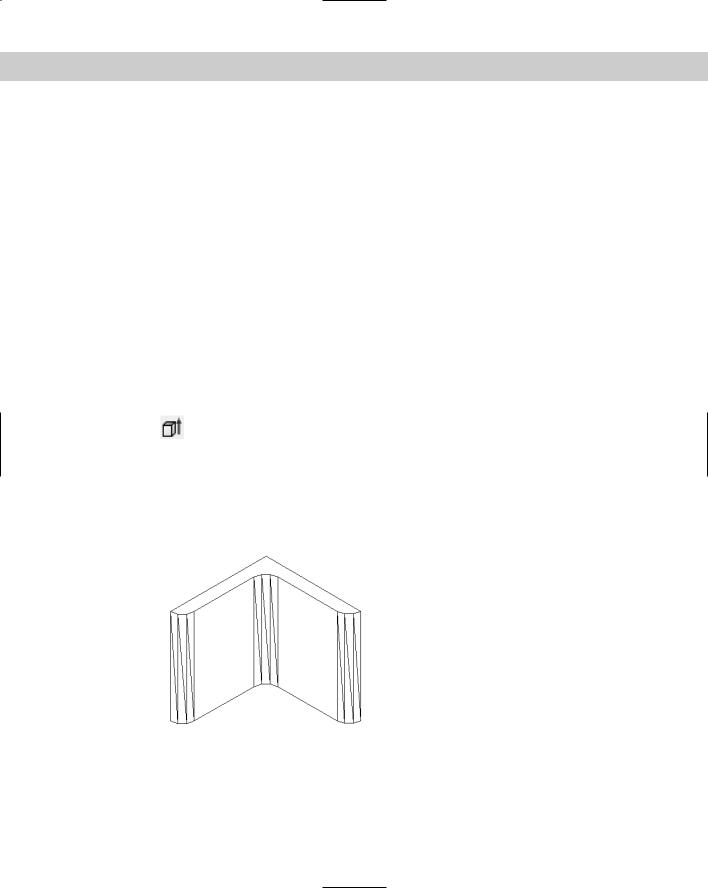
2.Save the file as ab24-02.dwg in your AutoCAD Bible folder. If the Solids toolbar is not displayed, right-click any toolbar and choose Solids. Make sure that OSNAP is on. Set running object snaps for endpoint and midpoint. This is a small mounting angle, shown in an edge view.
3.The angle is made up of lines and arcs. To extrude it, you need to change it into a polyline or region. To change it into a polyline, choose Modify Object Polyline. Follow the prompts:
Select polyline or [Multiple]: Select any object on the angle. Object selected is not a polyline
Do you want to turn it into one? <Y> Right-click.
Enter an option [Close/Join/Width/Edit vertex/Fit/Spline/Decurve/Ltype gen/Undo]: Right-click and choose Join.
Select objects: Use a window to select all of the objects in the angle.
Select objects: Right-click. 6 segments added to polyline
Enter an option [Open/Join/Width/Edit vertex/Fit/Spline/Decurve/Ltype gen/Undo]: Right-click and choose Enter.
4.Choose Extrude from the Solids toolbar. Select the mounting angle, and then right-
click to end object selection. At the Specify height of extrusion or [Path]: prompt, type 3 . At the Specify angle of taper for extrusion <0>: prompt, press Enter to accept the default.
5.Choose View 3D Views SE Isometric.
6.Apply the HIDE command.
7.Save your drawing. It should look like Figure 24-11.
Figure 24-11: The completed mounting angle.
760 Part IV Drawing in Three Dimensions
The mounting angle should have two holes in it. You would create the holes using the SUBTRACT command, which is covered later in this chapter.
Drawing Revolved Solids
The REVOLVE command creates solids from closed profiles. (By contrast, the REVSURF command, which creates surfaces, revolves an open profile around an axis.) You can revolve closed 2D polylines, circles, ellipses, closed splines, and regions.
The DELOBJ system variable affects whether the original objects are deleted. The default setting is 1 (delete objects). Set DELOBJ to 0 (zero) to retain the original objects.
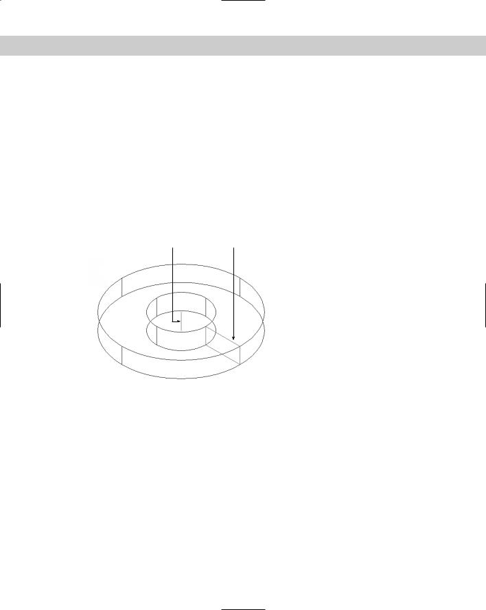
Figure 24-12 shows a solid created by revolving a rectangle around a line. You can also create this solid by drawing two circles and extruding them and then subtracting the smaller circle from the larger one — it just depends on which technique you’re more comfortable with.
Axis of revolution |
Original object (rectangle) |
Figure 24-12: A solid created by revolving a rectangle around a line.
To create a revolved solid, follow these steps:
1. Choose Revolve from the Solids toolbar.
2.At the Select objects: prompt, select one or more closed objects.
3.At the Specify start point for axis of revolution or define axis by [Object/X (axis)/Y (axis)]: prompt, you can pick two points to create an axis of revolution. You can also select an object as an axis by using a line or one segment of a polyline. Use the X or Y options to revolve the object around the X or Y axes.
4.At the Specify angle of revolution <360>: prompt, press Enter to revolve the object 360 degrees or type an angle, either positive or negative.
As with the REVSURF command, you need to determine the positive direction of rotation if you’re revolving less than 360 degrees. (Of course, it may be quicker to try one way and just do it the other way if it doesn’t turn out right.) Here’s how to figure it out: