

- •Contents
- •Contents at a Glance
- •Acknowledgments
- •Preface
- •Is This Book for You?
- •How This Book Is Organized
- •How to Use This Book
- •Doing the Exercises
- •Conventions Used in This Book
- •What the Icons Mean
- •About the CD-ROM
- •Other Information
- •Contacting the Author
- •Foreword
- •Credits
- •About the Author
- •Summary
- •AutoCAD’s Advantages
- •Comparing AutoCAD and AutoCAD LT
- •Starting AutoCAD and AutoCAD LT
- •Creating a New Drawing
- •Using the AutoCAD and AutoCAD LT Interface
- •Creating a New Folder
- •Using the Interface
- •Saving a Drawing
- •Closing a Drawing and Exiting from AutoCAD and AutoCAD LT
- •Summary
- •Creating a New Drawing from a Template
- •Working with Templates
- •Opening a Drawing with Default Settings
- •Opening an Existing Drawing
- •Using an Existing Drawing as a Prototype
- •Saving a Drawing Under a New Name
- •Summary
- •The Command Line and Dynamic Input
- •Command Techniques
- •Of Mice and Pucks
- •Getting Help
- •Summary
- •Typing Coordinates
- •Displaying Coordinates
- •Picking Coordinates on the Screen
- •Overriding Coordinate Settings
- •Locating Points
- •Summary
- •Choosing Unit Types
- •Drawing Limits
- •Understanding Scales
- •Creating a Title Block
- •Specifying Common Setup Options
- •Customizing with the MVSETUP Command
- •Using the Setup Wizards
- •Summary
- •Using the LINE Command
- •Drawing Rectangles
- •Drawing Polygons
- •Creating Construction Lines
- •Creating Rays
- •Summary
- •Drawing Circles
- •Drawing Arcs
- •Creating Ellipses and Elliptical Arcs
- •Making Donuts
- •Placing Points
- •Summary
- •Panning
- •Using the ZOOM Command
- •Using Aerial View
- •Saving Named Views
- •Working with Tiled Viewports
- •Using Snap Rotation
- •Understanding User Coordinate Systems
- •Creating Isometric Drawings
- •Summary
- •Editing a Drawing
- •Selecting Objects
- •Summary
- •Copying and Moving Objects
- •Resizing Commands
- •Using Construction Commands
- •Creating a Revision Cloud
- •Hiding Objects with a Wipeout
- •Double-Clicking to Edit Objects
- •Grips
- •Editing with the Properties Palette
- •Selection Filters
- •Groups
- •Summary
- •Working with Layers
- •Changing Object Color, Linetype, and Lineweight
- •Working with Linetype Scales
- •Importing Layers and Linetypes from Other Drawings
- •Matching Properties
- •Summary
- •Drawing-Level Information
- •Object-Level Information
- •Measurement Commands
- •AutoCAD’s Calculator
- •Summary
- •Creating Single-Line Text
- •Understanding Text Styles
- •Creating Multiline Text
- •Creating Tables
- •Inserting Fields
- •Managing Text
- •Finding Text in Your Drawing
- •Checking Your Spelling
- •Customizing the spelling dictionary
- •Summary
- •Working with Dimensions
- •Drawing Linear Dimensions
- •Drawing Aligned Dimensions
- •Creating Baseline and Continued Dimensions
- •Dimensioning Arcs and Circles
- •Dimensioning Angles
- •Creating Ordinate Dimensions
- •Drawing Leaders
- •Using Quick Dimension
- •Editing Dimensions
- •Summary
- •Understanding Dimension Styles
- •Defining a New Dimension Style
- •Changing Dimension Styles
- •Creating Geometric Tolerances
- •Summary
- •Creating and Editing Polylines
- •Drawing and Editing Splines
- •Creating Regions
- •Creating Boundaries
- •Creating Hatches
- •Creating and Editing Multilines
- •Creating Dlines
- •Using the SKETCH Command
- •Digitizing Drawings with the TABLET Command
- •Summary
- •Preparing a Drawing for Plotting or Printing
- •Creating a Layout in Paper Space
- •Working with Plot Styles
- •Plotting a Drawing
- •Summary
- •Combining Objects into Blocks
- •Inserting Blocks and Files into Drawings
- •Managing Blocks
- •Creating and Using Dynamic Blocks
- •Using Windows Features
- •Working with Attributes
- •Summary
- •Understanding External References
- •Editing an Xref within Your Drawing
- •Controlling Xref Display
- •Managing Xrefs
- •Summary
- •Preparing for Database Connectivity
- •Connecting to Your Database
- •Linking Data to Drawing Objects
- •Creating Labels
- •Querying with the Query Editor
- •Working with Query Files
- •Summary
- •Working with 3D Coordinates
- •Using Elevation and Thickness
- •Working with the User Coordinate System
- •Summary
- •Working with the Standard Viewpoints
- •Using DDVPOINT
- •Working with the Tripod and Compass
- •Displaying a Quick Plan View
- •Shading Your Drawing
- •Using 3D Orbit
- •Using Tiled Viewports
- •Defining a Perspective View
- •Laying Out 3D Drawings
- •Summary
- •Drawing Surfaces with 3DFACE
- •Drawing Surfaces with PFACE
- •Creating Polygon Meshes with 3DMESH
- •Drawing Standard 3D Shapes
- •Drawing a Revolved Surface
- •Drawing an Extruded Surface
- •Drawing Ruled Surfaces
- •Drawing Edge Surfaces
- •Summary
- •Drawing Standard Shapes
- •Creating Extruded Solids
- •Drawing Revolved Solids
- •Creating Complex Solids
- •Sectioning and Slicing Solids
- •Using Editing Commands in 3D
- •Editing Solids
- •Listing Solid Properties
- •Summary
- •Understanding Rendering
- •Creating Lights
- •Creating Scenes
- •Working with Materials
- •Using Backgrounds
- •Doing the Final Render
- •Summary
- •Accessing Drawing Components with the DesignCenter
- •Accessing Drawing Content with Tool Palettes
- •Setting Standards for Drawings
- •Organizing Your Drawings
- •Working with Sheet Sets
- •Maintaining Security
- •Keeping Track of Referenced Files
- •Handling Errors and Crashes
- •Managing Drawings from Prior Releases
- •Summary
- •Importing and Exporting Other File Formats
- •Working with Raster Images
- •Pasting, Linking, and Embedding Objects
- •Summary
- •Sending Drawings
- •Opening Drawings from the Web
- •Creating Object Hyperlinks
- •Publishing Drawings
- •Summary
- •Working with Customizable Files
- •Creating Keyboard Shortcuts for Commands
- •Customizing Toolbars
- •Customizing Tool Palettes
- •Summary
- •Creating Macros with Script Files
- •Creating Slide Shows
- •Creating Slide Libraries
- •Summary
- •Creating Linetypes
- •Creating Hatch Patterns
- •Summary
- •Creating Shapes
- •Creating Fonts
- •Summary
- •Working with the Customization File
- •Customizing a Menu
- •Summary
- •Introducing Visual LISP
- •Getting Help in Visual LISP
- •Working with AutoLISP Expressions
- •Using AutoLISP on the Command Line
- •Creating AutoLISP Files
- •Summary
- •Creating Variables
- •Working with AutoCAD Commands
- •Working with Lists
- •Setting Conditions
- •Managing Drawing Objects
- •Getting Input from the User
- •Putting on the Finishing Touches
- •Summary
- •Understanding Local and Global Variables
- •Working with Visual LISP ActiveX Functions
- •Debugging Code
- •Summary
- •Starting to Work with VBA
- •Writing VBA Code
- •Getting User Input
- •Creating Dialog Boxes
- •Modifying Objects
- •Debugging and Trapping Errors
- •Moving to Advanced Programming
- •Summary
- •A Final Word
- •Installing AutoCAD and AutoCAD LT
- •Configuring and Using Workspaces
- •Configuring AutoCAD
- •Starting AutoCAD Your Way
- •Configuring a Plotter
- •Discovering AutoCAD and AutoCAD LT
- •Accessing Technical Support
- •Autodesk User Groups
- •Internet Resources
- •System Requirements
- •Using the CD-ROM with Microsoft Windows
- •What’s on the CD-ROM
- •Troubleshooting
- •Index
746 Part IV Drawing in Three Dimensions
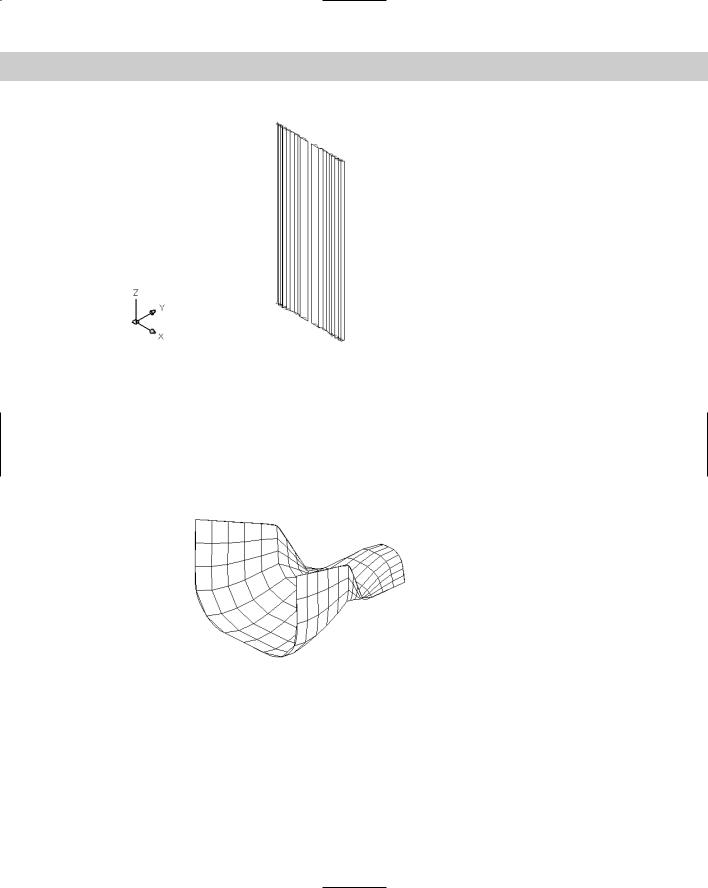
Figure 23-33: The completed drapes.
Drawing Edge Surfaces
You may have several edges and want to create a surface that extends between them. You can use the EDGESURF command to create unusual surfaces bound by four touching objects. The objects can be lines, arcs, splines, or polylines (2D or 3D). EDGESURF creates a polygon mesh that approximates a Coon’s surface patch mesh — a surface defined by four edges. Figure 23-34 shows an edge surface.
Figure 23-34: An edge surface created with the
EDGESURF command.
Use the SURFTAB1 and SURFTAB2 system variables to vary the displayed lines in each direction.
Follow these steps to create an edge surface:
1.Draw the four objects to create a boundary for the surface. They must touch, so use Endpoint object snaps to create them or to move them into place.
Chapter 23 Creating 3D Surfaces 747
2. Choose Edge Surface from the Surfaces toolbar.
3.AutoCAD prompts you to select edges 1 through 4. You can select them in any order.
Creating the four edges involves moving from one UCS to another UCS because they’re all in 3D. It helps to create a bounding box for your object using the AI_BOX command. You can then use the corners of the box to define your UCSs.
On the |
The drawing used in the following exercise on drawing edge surfaces, ab23-g.dwg, is in the |
CD-ROM |
Drawings folder on the CD-ROM. |
STEPS: Drawing Edge Surfaces
1.Open ab23-g.dwg from the CD-ROM.
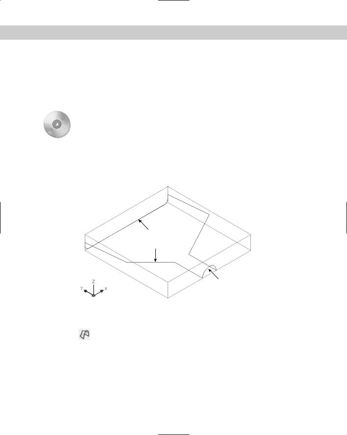
2.Save it as ab23-07.dwg in your AutoCAD Bible folder. You see four curves in a bounding box, as shown in Figure 23-35. In this exercise, you use the curves to draw a dustpan.
3 4
2
1
Figure 23-35: The four curves are the basis for creating an edge surface.
3.Freeze the Const layer.
4.Choose Edge Surface from the Surfaces toolbar. At the prompts, select 1, 2, 3, and 4 in Figure 23-35.
5.Choose View Hide to see the result.
6.Save your drawing. It should look like Figure 23-36. It’s either a dustpan or a starship — your choice.
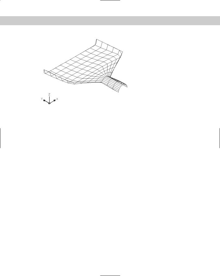
748 Part IV Drawing in Three Dimensions
Figure 23-36: The completed dustpan — or starship.
Summary
In this chapter, you read all about 3D surfaces. You read about:
Creating surfaces by using the 3DFACE command and controlling the visibility of the lines between the faces
Creating polyface meshes
Creating surfaces with 3D polygon meshes, including the basic shapes — box, wedge, pyramid, cone, sphere, dome, dish, and torus
Making a surface by revolving a profile around an axis
Extruding a curve
Creating a ruled surface between two curves
Making an edge surface from four curves
In the next chapter, you discover how to create true solids (well, true electronic ones, at least) as well as how to edit in 3D.
|
|
|
Creating Solids
and Editing in 3D
Although you can create great-looking models with surfaces, if you want truly realistic models, you need to create solids. After all, in real life, objects have solidity. Even a thin object such as a wastepaper
basket or a drape has some thickness. Solids enable you to create more realistic models than surfaces. You can also combine or subtract solids and get information about their physical properties.
AutoCAD LT doesn’t draw solids. For the 3D capabilities of AutoCAD LT, see Chapters 21 and 22.
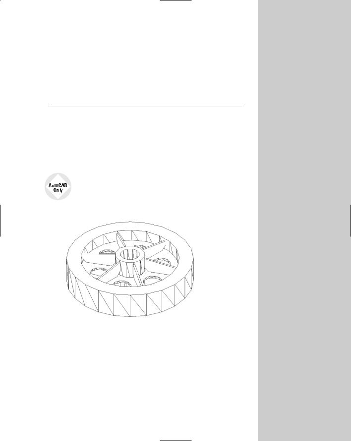
Figure 24-1 shows a complex model created using solids.
Figure 24-1: You can create complex and realistic models using solids.
Thanks to Hans-Joachim Fach, Bremen, Germany, for this drawing.
To work with solids, display the Solids toolbar by right-clicking any toolbar and choosing Solids from the Toolbars dialog box. You can also access all of the solids commands by choosing Draw Solids and then choosing the specific command from the submenu that opens.
Drawing Standard Shapes
24C H A P T E R
In This Chapter
Drawing standard shapes
Creating extruded solids
Drawing revolved solids
Creating complex solids
Sectioning
and slicing solids
Using editing commands in 3D
Editing solids
As with surfaces, AutoCAD makes it easy to create most standard geometrical shapes. The prompts are similar to the surface commands, but there are some slight differences.
750 Part IV Drawing in Three Dimensions
Drawing a box
The box is one of the most commonly used 3D objects and is often the basis for more complex models. Figure 24-2 shows a solid box after using the HIDE command. Visually, it looks the same as a surface box.
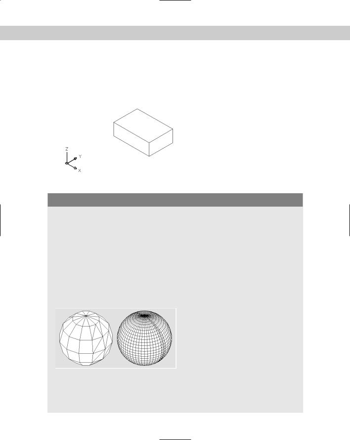
Figure 24-2: A solid box.
Controlling the Display of Solids
Curved surfaces are drawn using segments. When you draw a surface sphere, AutoCAD prompts you for the number of lines to draw. The wireframe display of all of the curved solids in a drawing is controlled by the ISOLINES system variable. The default, 4, provides a bare minimum of curved lines to let you view the outlines of the curve and results in the quickest display. Increasing the ISOLINES value improves the visual result but slows down the drawing display. Generally, you can find a happy medium based on the size of your drawing, the speed of your computer, and your personal preferences. The ISOLINES variable affects only wireframe display — it has no effect when you use the HIDE or SHADEMODE commands. Figure 24-3 shows the effect of varying the ISOLINES setting. When you change the ISOLINES value, use the REGEN command to see the result on existing objects. The FACETRES system variable is the 3D version of VIEWRES, and it determines the display of curved surfaces and solids when using the HIDE, SHADEMODE, or RENDER commands. You can set FACETRES from 0.01 to 10.0. Here you see a hidden sphere at FACETRES settings of 0.05 (left) and 5.0 (right). The default is 0.5, which is generally a happy medium.
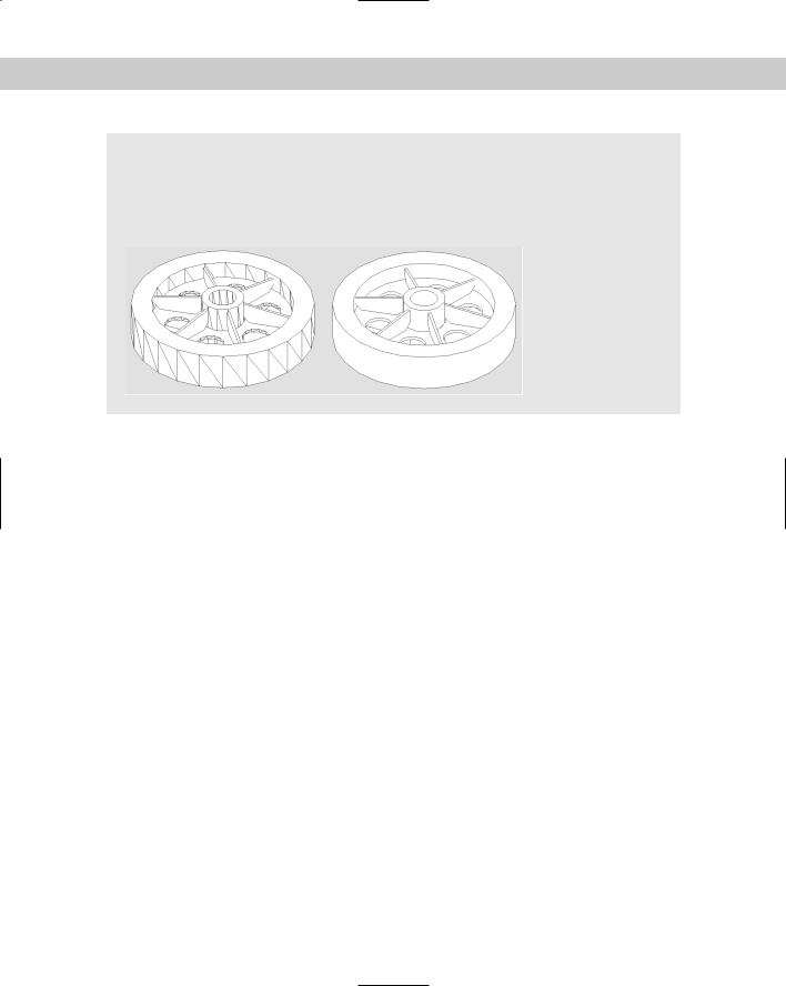
The DISPSILH system variable determines whether AutoCAD creates a silhouette of a model based on the current viewpoint. The effect is most noticeable after using the HIDE command. The left-hand model here shows the result of setting DISPSILH to 0 (the default) after using the HIDE command. The right-hand model shows the results of setting DISPSILH to 1 (on) after using the
Chapter 24 Creating Solids and Editing in 3D |
751 |
HIDE command. You can see that the right-hand model provides a very uncluttered display. When you set DISPSILH to 1 in wireframe display, AutoCAD adds silhouette lines. For complex objects, you may find that DISPSILH slows down your display. This is a complicated matter for AutoCAD to compute. So, you may want to set DISPSILH back to 0 (zero) after using the HIDE command, depending on the models on which you’re working.
To draw a box, follow these steps:
1. Choose Box from the Solids toolbar.
2.At the Specify corner of box or [CEnter] <0,0,0>: prompt, specify any corner of the box or right-click and choose Center to specify the 3D center of the box.
3.If you specify the corner (the default), you then see the Specify corner or [Cube/Length]: prompt.
The default is to pick the opposite corner in the XY plane. AutoCAD then asks you for the height in the Z direction. This completes the box.
If you specify the length in the XY plane, AutoCAD asks you for a width and a height. If you use the Cube option, AutoCAD asks for one length and completes the box.
4.If you specify the center, you see the Specify center of box <0,0,0>: prompt. Specify the center of the box. The Specify corner or [Cube/Length]: prompt appears.
If you pick the corner of the box, AutoCAD completes the box by calculating the length, width, and height from the two points — the center and the corner.
If you specify the length, AutoCAD then asks for a width and a height.
If you use the Cube option, AutoCAD asks for a length and completes the box.
You can specify a negative length, width, or height to build the box in the negative direction. If you specify the center of the cube, don’t forget that the center’s Z coordinate is different from the corner’s Z coordinate. AutoCAD always creates the box parallel to the XY plane.
Drawing a sphere
Spheres are not used very often alone but can be the basis for more complex models — they certainly look pretty! Figure 24-3 shows two solid spheres. The left sphere uses the default ISOLINE value of 4. The right sphere uses an ISOLINE value of 8.
752 Part IV Drawing in Three Dimensions
Figure 24-3: Two solid spheres, with ISOLINES set at 4 (left) and 8 (right).
To draw a sphere, follow these steps:
1. Choose Sphere from the Solids toolbar.
2.At the Specify center of sphere <0,0,0>: prompt, specify the center of the sphere. If you want the sphere to lie on the XY plane, the Z coordinate of the center should be equal to the radius of the sphere.
3.At the Specify radius of sphere or [Diameter]: prompt, type the radius or rightclick and choose Diameter to specify the diameter.
Drawing a cylinder
Cylinders are very common in 3D drawing. Figure 24-4 shows four solid cylinders. The grid helps you visualize the XY plane. You can draw cylinders with circular or elliptical bases. By specifying the center of the top of the cylinder separately, you can draw it at an angle.
Figure 24-4: Some solid cylinders.
Follow these steps to draw a cylinder:
1.  Choose Cylinder from the Solids toolbar.
Chapter 24 Creating Solids and Editing in 3D |
753 |
2.At the Specify center point for base of cylinder or [Elliptical] <0,0,0>: prompt, specify the center point for a circular cylinder or choose the Elliptical option to define an ellipse as a base.
If you specified a center point, at the Specify radius for base of cylinder or [Diameter]: prompt, specify a radius or use the Diameter option to specify the diameter.
If you chose the Elliptical option, use the prompts to define the elliptical base.
3.At the Specify height of cylinder or [Center of other end]: prompt, specify the height or use the Center of Other End option to specify the center of the top of the cylinder.
Drawing a cone
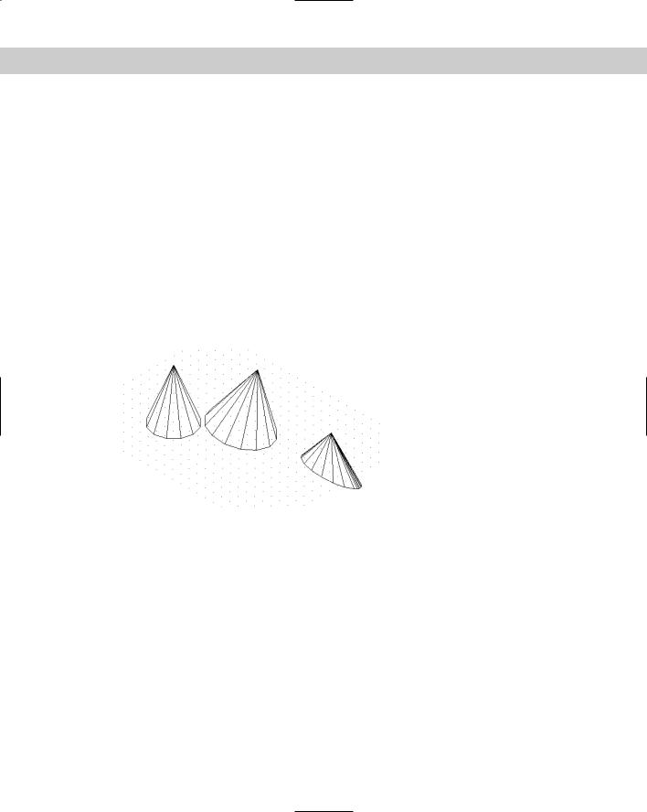
You can draw cones with circular or elliptical bases. By specifying a negative height, you can create an inverted cone (like an ice cream cone). By specifying the apex, you can draw cones on an angle from the XY plane. Figure 24-5 shows some cones.
Figure 24-5: Cones with varying heights and bases.
Follow these steps to draw a cone:
1. Choose Cone from the Solids toolbar.
2.At the Specify center point for base of cone or [Elliptical] <0,0,0>: prompt, specify the center of the base if you want a circular cone. Otherwise, use the Elliptical option to define an elliptical base.
If you specified a center point, at the Specify radius for base of cone or [Diameter]: prompt, specify a radius or use the Diameter option to specify the diameter.
If you chose the Elliptical option, use the prompts to define the elliptical base.
3.At the Specify height of cone or [Apex]: prompt, specify the height or use the Apex option to specify the coordinate of the apex. A temporary line marks the center of the base so that you can use relative coordinates for the apex.
754 Part IV Drawing in Three Dimensions
Drawing a wedge
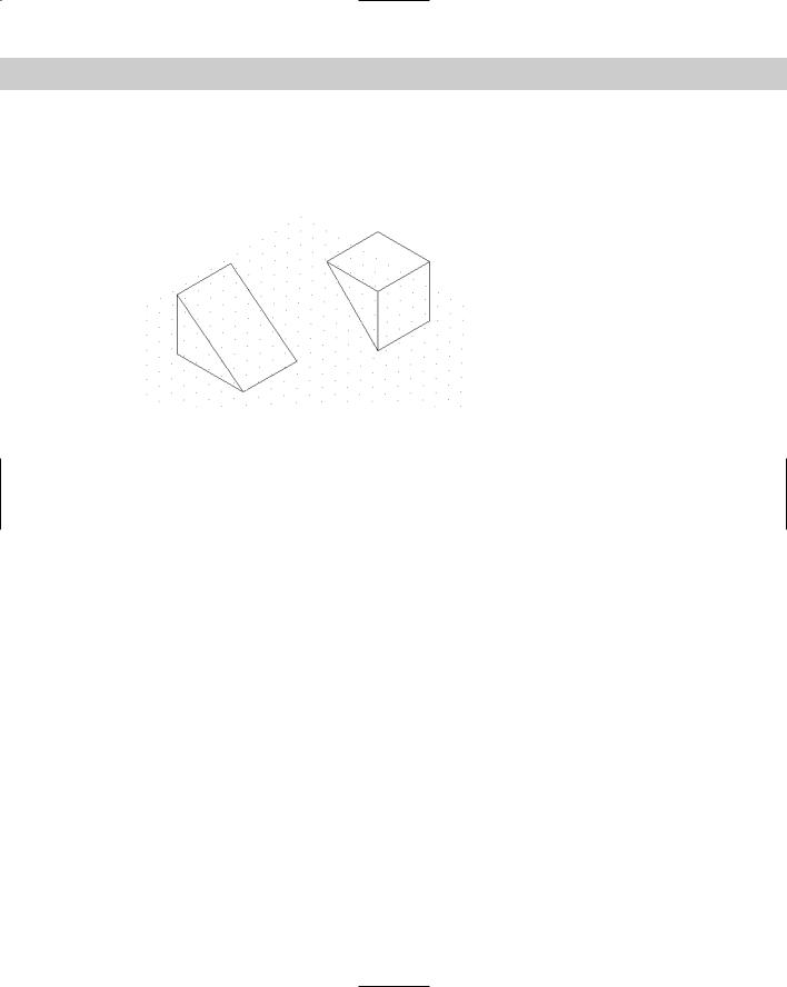
A wedge is a box sliced in half. The prompts are virtually the same as the Box command. Figure 24-6 shows two wedges.
Figure 24-6: Two solid wedges.
To create a wedge, follow these steps:
1. Choose Wedge from the Solids toolbar.
2.At the Specify first corner of wedge or [CEnter] <0,0,0>: prompt, specify any corner of the wedge or type c and use the Center option to specify the 3D center of the wedge.
3.If you specify the corner (the default), you then see the Specify corner or [Cube/Length]: prompt.
The default is to pick the opposite corner in the XY plane. AutoCAD then asks you for the height in the Z direction. This completes the wedge.
If you specify the length in the XY plane, AutoCAD asks you for a width and a height.
If you use the Cube option, AutoCAD asks for one length and completes the wedge. For positive lengths, the wedge slopes in the X direction.
4.If you specify the center, you see the Specify center of wedge <0,0,0>: prompt. Specify the center point. The Specify opposite corner or [Cube/Length]: prompt displays.
If you pick the corner of the wedge, AutoCAD completes the wedge by calculating the length, width, and height from the two points — the center and the corner.
If you specify the length, AutoCAD then asks for a width and a height.
If you use the Cube option, AutoCAD asks for a length and completes the wedge.
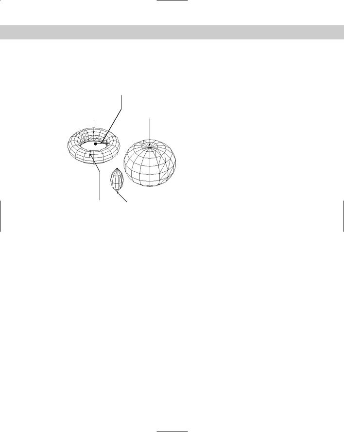
Drawing a torus
A torus is a solid 3D donut. Figure 24-7 shows some examples. You can make some unusual shapes by varying the torus and tube radii. If the torus radius is negative and the tube radius is larger than the absolute value of the torus radius (for example, –2 and 3), you create a
Chapter 24 Creating Solids and Editing in 3D |
755 |
lemon (or football) shape. If the tube radius is larger than the torus radius, you create a puckered ball (or apple) shape. (You cannot get such unusual shapes using the Torus shape on the Surfaces toolbar.)
Radius of torus
Torus radius = 3 |
Torus radius = 1 |
Tube radius = 1 |
Tube radius = 3 |
Radius of tube |
Torus radius = -2 |
|
Tube radius = 3 |
Figure 24-7: Torus examples.
To create a torus, follow these steps:
1. Choose Torus from the Solids toolbar.
2.At the Specify center of torus <0,0,0>: prompt, specify the center of the torus (the center of the hole).
3.At the Specify radius of torus or [Diameter]: prompt, specify the radius of the entire torus or use the Diameter option to specify the diameter.
4.At the Specify radius of tube or [Diameter]: prompt, specify the radius of just the tube or use the Diameter option to specify the diameter.
STEPS: Drawing Standard 3D Solids
1.Start a new drawing using the acad.dwt template.
2.Save the file as ab24-01.dwg in your AutoCAD Bible folder. If the Solids toolbar is not displayed, right-click any toolbar, and choose Solids. Turn on OSNAP and OTRACK. Set running object snaps for endpoint, midpoint, and center.
3. Choose Box from the Solids toolbar. Follow the prompts:
Specify corner of box or [CEnter] <0,0,0>: 3,3
Specify corner or [Cube/Length]: Right-click and choose Length. Specify length: 3
Specify width: 2 Specify height: 1
756 Part IV Drawing in Three Dimensions
4. Choose Cylinder from the Solids toolbar. Follow the prompts:
Specify center point for base of cylinder or [Elliptical] <0,0,0>:
Pass the cursor over the midpoint of the right side of the box to acquire it. Move the cursor to the midpoint of the bottom side of the box to acquire it. Move the cursor to the middle of the box’s top
until you see the tooltip listing both midpoints, and click.
Specify radius for base of cylinder or [Diameter]: .5 Specify height of cylinder or [Center of other end]: 1
5.To see the result, choose View 3D Views SE Isometric. Then choose Zoom Out from the Zoom flyout.
6.Choose Cone from the Solids toolbar. At the Specify center point for base of cone or [Elliptical] <0,0,0>: prompt, type 7,5 . At the Specify radius for base of cone or [Diameter]: prompt, type 1 . At the Specify height of cone
or [Apex]: prompt, type –4 .
7.Choose Sphere from the Solids toolbar. At the Specify center of sphere
<0,0,0>: prompt, use the Center object snap to pick the center of the cone’s base. At the Specify radius of sphere or [Diameter]: prompt, type 1 .
8.Type isolines . Set the new value to 8. Use the REGEN command to see the result.
9.Choose Zoom Extents from the Zoom flyout of the Standard toolbar.
10.Apply the HIDE command. Notice that the objects appear realistic, regardless of the ISOLINES setting.
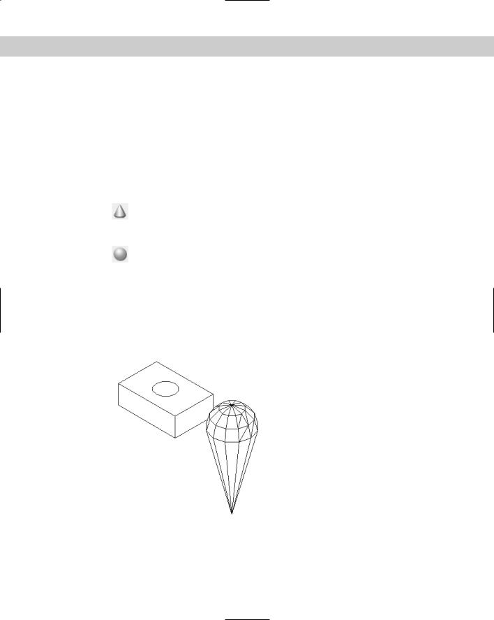
11.Save your drawing. It should look like Figure 24-8.
Figure 24-8: The four solids.