

- •Contents
- •Contents at a Glance
- •Acknowledgments
- •Preface
- •Is This Book for You?
- •How This Book Is Organized
- •How to Use This Book
- •Doing the Exercises
- •Conventions Used in This Book
- •What the Icons Mean
- •About the CD-ROM
- •Other Information
- •Contacting the Author
- •Foreword
- •Credits
- •About the Author
- •Summary
- •AutoCAD’s Advantages
- •Comparing AutoCAD and AutoCAD LT
- •Starting AutoCAD and AutoCAD LT
- •Creating a New Drawing
- •Using the AutoCAD and AutoCAD LT Interface
- •Creating a New Folder
- •Using the Interface
- •Saving a Drawing
- •Closing a Drawing and Exiting from AutoCAD and AutoCAD LT
- •Summary
- •Creating a New Drawing from a Template
- •Working with Templates
- •Opening a Drawing with Default Settings
- •Opening an Existing Drawing
- •Using an Existing Drawing as a Prototype
- •Saving a Drawing Under a New Name
- •Summary
- •The Command Line and Dynamic Input
- •Command Techniques
- •Of Mice and Pucks
- •Getting Help
- •Summary
- •Typing Coordinates
- •Displaying Coordinates
- •Picking Coordinates on the Screen
- •Overriding Coordinate Settings
- •Locating Points
- •Summary
- •Choosing Unit Types
- •Drawing Limits
- •Understanding Scales
- •Creating a Title Block
- •Specifying Common Setup Options
- •Customizing with the MVSETUP Command
- •Using the Setup Wizards
- •Summary
- •Using the LINE Command
- •Drawing Rectangles
- •Drawing Polygons
- •Creating Construction Lines
- •Creating Rays
- •Summary
- •Drawing Circles
- •Drawing Arcs
- •Creating Ellipses and Elliptical Arcs
- •Making Donuts
- •Placing Points
- •Summary
- •Panning
- •Using the ZOOM Command
- •Using Aerial View
- •Saving Named Views
- •Working with Tiled Viewports
- •Using Snap Rotation
- •Understanding User Coordinate Systems
- •Creating Isometric Drawings
- •Summary
- •Editing a Drawing
- •Selecting Objects
- •Summary
- •Copying and Moving Objects
- •Resizing Commands
- •Using Construction Commands
- •Creating a Revision Cloud
- •Hiding Objects with a Wipeout
- •Double-Clicking to Edit Objects
- •Grips
- •Editing with the Properties Palette
- •Selection Filters
- •Groups
- •Summary
- •Working with Layers
- •Changing Object Color, Linetype, and Lineweight
- •Working with Linetype Scales
- •Importing Layers and Linetypes from Other Drawings
- •Matching Properties
- •Summary
- •Drawing-Level Information
- •Object-Level Information
- •Measurement Commands
- •AutoCAD’s Calculator
- •Summary
- •Creating Single-Line Text
- •Understanding Text Styles
- •Creating Multiline Text
- •Creating Tables
- •Inserting Fields
- •Managing Text
- •Finding Text in Your Drawing
- •Checking Your Spelling
- •Customizing the spelling dictionary
- •Summary
- •Working with Dimensions
- •Drawing Linear Dimensions
- •Drawing Aligned Dimensions
- •Creating Baseline and Continued Dimensions
- •Dimensioning Arcs and Circles
- •Dimensioning Angles
- •Creating Ordinate Dimensions
- •Drawing Leaders
- •Using Quick Dimension
- •Editing Dimensions
- •Summary
- •Understanding Dimension Styles
- •Defining a New Dimension Style
- •Changing Dimension Styles
- •Creating Geometric Tolerances
- •Summary
- •Creating and Editing Polylines
- •Drawing and Editing Splines
- •Creating Regions
- •Creating Boundaries
- •Creating Hatches
- •Creating and Editing Multilines
- •Creating Dlines
- •Using the SKETCH Command
- •Digitizing Drawings with the TABLET Command
- •Summary
- •Preparing a Drawing for Plotting or Printing
- •Creating a Layout in Paper Space
- •Working with Plot Styles
- •Plotting a Drawing
- •Summary
- •Combining Objects into Blocks
- •Inserting Blocks and Files into Drawings
- •Managing Blocks
- •Creating and Using Dynamic Blocks
- •Using Windows Features
- •Working with Attributes
- •Summary
- •Understanding External References
- •Editing an Xref within Your Drawing
- •Controlling Xref Display
- •Managing Xrefs
- •Summary
- •Preparing for Database Connectivity
- •Connecting to Your Database
- •Linking Data to Drawing Objects
- •Creating Labels
- •Querying with the Query Editor
- •Working with Query Files
- •Summary
- •Working with 3D Coordinates
- •Using Elevation and Thickness
- •Working with the User Coordinate System
- •Summary
- •Working with the Standard Viewpoints
- •Using DDVPOINT
- •Working with the Tripod and Compass
- •Displaying a Quick Plan View
- •Shading Your Drawing
- •Using 3D Orbit
- •Using Tiled Viewports
- •Defining a Perspective View
- •Laying Out 3D Drawings
- •Summary
- •Drawing Surfaces with 3DFACE
- •Drawing Surfaces with PFACE
- •Creating Polygon Meshes with 3DMESH
- •Drawing Standard 3D Shapes
- •Drawing a Revolved Surface
- •Drawing an Extruded Surface
- •Drawing Ruled Surfaces
- •Drawing Edge Surfaces
- •Summary
- •Drawing Standard Shapes
- •Creating Extruded Solids
- •Drawing Revolved Solids
- •Creating Complex Solids
- •Sectioning and Slicing Solids
- •Using Editing Commands in 3D
- •Editing Solids
- •Listing Solid Properties
- •Summary
- •Understanding Rendering
- •Creating Lights
- •Creating Scenes
- •Working with Materials
- •Using Backgrounds
- •Doing the Final Render
- •Summary
- •Accessing Drawing Components with the DesignCenter
- •Accessing Drawing Content with Tool Palettes
- •Setting Standards for Drawings
- •Organizing Your Drawings
- •Working with Sheet Sets
- •Maintaining Security
- •Keeping Track of Referenced Files
- •Handling Errors and Crashes
- •Managing Drawings from Prior Releases
- •Summary
- •Importing and Exporting Other File Formats
- •Working with Raster Images
- •Pasting, Linking, and Embedding Objects
- •Summary
- •Sending Drawings
- •Opening Drawings from the Web
- •Creating Object Hyperlinks
- •Publishing Drawings
- •Summary
- •Working with Customizable Files
- •Creating Keyboard Shortcuts for Commands
- •Customizing Toolbars
- •Customizing Tool Palettes
- •Summary
- •Creating Macros with Script Files
- •Creating Slide Shows
- •Creating Slide Libraries
- •Summary
- •Creating Linetypes
- •Creating Hatch Patterns
- •Summary
- •Creating Shapes
- •Creating Fonts
- •Summary
- •Working with the Customization File
- •Customizing a Menu
- •Summary
- •Introducing Visual LISP
- •Getting Help in Visual LISP
- •Working with AutoLISP Expressions
- •Using AutoLISP on the Command Line
- •Creating AutoLISP Files
- •Summary
- •Creating Variables
- •Working with AutoCAD Commands
- •Working with Lists
- •Setting Conditions
- •Managing Drawing Objects
- •Getting Input from the User
- •Putting on the Finishing Touches
- •Summary
- •Understanding Local and Global Variables
- •Working with Visual LISP ActiveX Functions
- •Debugging Code
- •Summary
- •Starting to Work with VBA
- •Writing VBA Code
- •Getting User Input
- •Creating Dialog Boxes
- •Modifying Objects
- •Debugging and Trapping Errors
- •Moving to Advanced Programming
- •Summary
- •A Final Word
- •Installing AutoCAD and AutoCAD LT
- •Configuring and Using Workspaces
- •Configuring AutoCAD
- •Starting AutoCAD Your Way
- •Configuring a Plotter
- •Discovering AutoCAD and AutoCAD LT
- •Accessing Technical Support
- •Autodesk User Groups
- •Internet Resources
- •System Requirements
- •Using the CD-ROM with Microsoft Windows
- •What’s on the CD-ROM
- •Troubleshooting
- •Index
736 Part IV Drawing in Three Dimensions
14.Choose Pyramid from the Surfaces toolbar. Follow the prompts to draw a pyramidal pepper shaker:
Specify first corner point for base of pyramid: 2'6,2'6 Specify second corner point for base of pyramid: @1,0 Specify third corner point for base of pyramid: @0,1
Specify fourth corner point for base of pyramid or [Tetrahedron]:
@-1,0
Specify apex point of pyramid or [Ridge/Top]: t
Specify first corner point for top of pyramid: @1/4,1/4,3 Specify second corner point for top of pyramid: @-1/4,1/4,3 Specify third corner point for top of pyramid: @-1/4,-1/4,3 Specify fourth corner point for top of pyramid: @1/4,-1/4,3
15.Choose View Hide. You can now visualize the drawing better.
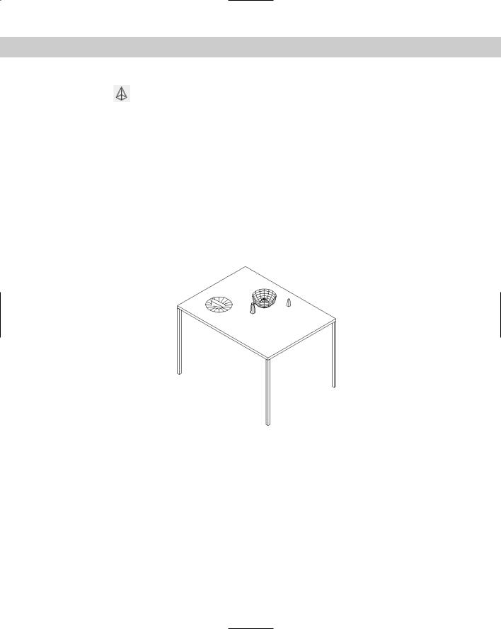
16.Save your drawing. It should look like Figure 23-22. If you look carefully, you’ll see that the edge of the cheese wedge goes slightly through the plate.
Figure 23-22: The table with a plate, wedge of cheese, bowl, orange, and nonmatching salt and pepper shakers.
Drawing a Revolved Surface
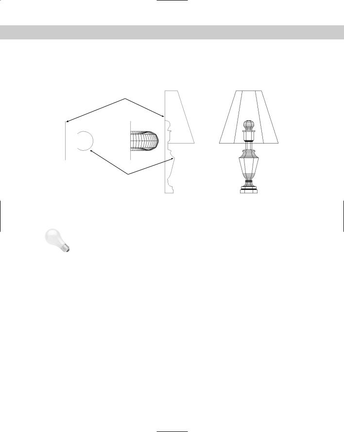
A common way to define a surface is to revolve an outline around an axis. You can create some very complex surfaces in this way. The REVSURF command takes an object that defines an outline or profile — AutoCAD also calls it a path curve — and revolves it around an axis, creating a 3D polygon mesh. Figure 23-23 shows two examples of revolved surfaces.
Chapter 23 Creating 3D Surfaces 737
The path curve must be one object — a line, arc, circle, polyline, ellipse, or elliptical arc. It can be open, like the path curves shown in Figure 23-23, or closed. A closed path curve creates a model that is closed in the N direction.
Axis of rotation
Path curve
Revolved 90o |
Revolved 360o |
Figure 23-23: Two revolved surfaces.
Tip |
If you have several adjoining objects that you’d like to use as one path curve, remember that |
|
you can use PEDIT to change lines and arcs to polylines and join them together. For more |
|
information, see Chapter 16. |
Determining the angle of rotation
You can start the angle of rotation at any angle; it doesn’t have to start on the plane of the path curve. You can rotate the path curve to any angle. Of course, rotating the path curve 360 degrees closes the model (in the M direction of the mesh).
When you rotate the path curve less than 360 degrees, you need to know which way to rotate. You can specify a positive (counterclockwise) or negative (clockwise) angle.
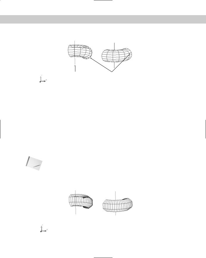
The point at which you pick the axis of rotation object affects the positive direction of rotation. Then you use the right-hand rule to determine which way the path curve will rotate around the axis. To do this, point your right thumb along the axis in the opposite direction from the endpoint closest to where you pick the axis. The direction in which your other fingers curl is the positive direction of rotation. Figure 23-24 shows the same model revolved in different directions. In the left model, the line of the axis was picked near the bottom endpoint. In the right model, the line of the axis was picked near the top endpoint.
738 Part IV Drawing in Three Dimensions
 Pick point
Pick point |
Path curve |
Figure 23-24: From the viewer’s point of view, the left revolved surface was rotated back 125 degrees, and the right revolved surface was rotated forward 125 degrees.
Setting the number of segments
You use the SURFTAB1 and SURFTAB2 system variables to determine how AutoCAD creates the mesh. AutoCAD calls this the wireframe density.
SURFTAB1 affects how the M direction — the direction of revolution — is displayed.
SURFTAB2 affects how the N direction — the path curve — is displayed.
The higher the setting, the more lines AutoCAD uses to display the model. However, if the path curve is a polyline with straight segments, AutoCAD just displays one line at each segment vertex.
In Figure 23-24, SURFTAB1 is 6 and SURFTAB2 is 12. Figure 23-25 shows the same model with SURFTAB1 at 20 and SURFTAB2 at 5 to show the contrast between the two.
Note Although you count M and N mesh sizes by vertices, you specify SURFTAB1 and SURFTAB2 by the number of surface areas that you want to see.
To set these system variables, type them on the command line and specify the new value that you want.
Figure 23-25: The same model re-created with SURFTAB1=20 and SURFTAB2=5.
Chapter 23 Creating 3D Surfaces 739
Using the REVSURF command
To create a revolved surface, follow these steps:
1.First create the path curve, which must be one object.
2.Draw the axis of revolution, usually a line.
3. Choose Revolved Surface from the Surfaces toolbar.
4.At the Select object to revolve: prompt, select the path curve object.
5.At the Select object that defines the axis of revolution: prompt, select the axis of revolution object.
6.At the Specify start angle <0>: prompt, press Enter to accept the default of 0 (zero) or type a start angle.
7.At the Specify included angle (+=ccw, -=cw) <360>: prompt, press Enter to revolve the surface 360 degrees or type a positive or negative angle.
You may need to create the path curve and the axis in a different plane than the one you use when revolving them. You can draw the path curve and axis in one UCS and use REVSURF in another. If the object doesn’t come out in the right direction, you can rotate the entire object when completed. Rotating objects in 3D is covered in the next chapter.
REVSURF retains the original path curve and axis objects. It helps to draw them in a different layer and color so that you can easily erase them afterward. Otherwise, they’re hard to distinguish from the revolved surface. Having them on a separate layer also helps if you need to redo the revolved surface — you can more easily avoid erasing them when you erase the revolved surface.
On the |
The drawing used in the following exercise on drawing revolved surfaces, ab23-d.dwg, is in |
CD-ROM |
the Drawings folder on the CD-ROM. |
STEPS: Drawing Revolved Surfaces
1.Open ab23-d.dwg from the CD-ROM.
2.Save it as ab23-04.dwg in your AutoCAD Bible folder. The path curve and axis are already drawn in a UCS that is revolved around the X axis of the World Coordinate System (WCS) by 90 degrees.
3. Choose Revolved Surface from the Surfaces toolbar.
4.At the Select object to revolve: prompt, select the polyline to the right.
5.At the Select object that defines the axis of revolution: prompt, select the line.
6.At the Specify start angle <0>: prompt, press Enter. At the Specify included angle (+=ccw, -=cw) <360>: prompt, press Enter to revolve the path curve in a full circle.
7.Choose Tools New UCS World to return to the WCS.
8.Choose View 3D Views SE Isometric.