

CHAPTER 7. GENERALIZED MUTUAL EXCLUSION CONSTRAINTS |
64 |
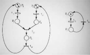
Figure 7.1: System in Example 7.1.
has optimal value x¤2 = 53 < k2 + 1, hence R(N; M0) \ M(w~1; k1) µ M(w~2; k2). This proves that the two constraints are equivalent for the given system.
The equivalence between constraints leads to the idea of simplification of a constraint. Given a constraint (w;~ k), we may look for a simpler, but equivalent, constraint. A constraint (w~0; k0) is simpler than (w;~ k) if w~0 < w~. In the next subsection we will see that simpler constraints require simpler control structure to be enforced. The next example shows another advantage of simplifying constraints.
Example 7.2. For the system in Figure 7.1a consider, in addition to the two constraints discussed in Example 7.1, the constraint (w~3; k3) with: w~3 = (0330)T ; k3 = 5. By definition, (w~2; k2) is simpler than (w~3; k3) that is simpler than (w~1; k1). It is immediate to see that M(w~3; k3) = M(w~2; k2), i.e., (w~3; k3) is equivalent to (w~2; k2) wrt hN; M0i. Since we have proved in Example 7.1 that (w~1; k1) is equivalent to (w~2; k2), the equivalence between (w~1; k1) and (w~3; k3) also follows.
Note, however, that if we try to use a LPP to prove that (w~1; k1) is redundant wrt R(N; M0) \ (w~3; k3) we have an inconclusive answer. In fact the LPP
|
|
|
x1 = max |
w~1T ¢ M |
||
|
|
|
s:t: |
~ |
T |
¢ M = 3; |
|
|
|
1 |
|
||
|
|
|
|
w~3T ¢ M · 5; |
||
|
|
|
|
|
|
~ |
|
|
|
|
M ¸ 0; |
||
has optimal value: x¤ |
= |
19 |
> 6, hence we cannot conclude that (w~1; k1) is redundant wrt |
|||
1 |
|
3 |
|
|
|
|
R(N; M0) \ (w~3; k3).
It is important, in the previous example, to pinpoint the advantage of using the simpler unweighted constraint (w~2; k2) rather than the weighted one (w~3; k3) to prove equivalence to (w~1; k1). The system considered in the example is a live marked graph, and the constraint set that defines the set of reachable markings has integer extremal points, hence any optimal solution of the Linear Programming Program is also a solution of the corresponding Integer Programming Problem. This property is preserved if we add any number of unweighted constraints to the constraint set that defines the set of reachable markings.

CHAPTER 7. GENERALIZED MUTUAL EXCLUSION CONSTRAINTS |
65 |
Figure 7.2: Reachable markings in Example 7.5.
7.2.2 Modeling Power of Generalized Mutual Exclusion Constraints
In this subsection we discuss the modeling power of GMEC, both weighted and unweighted. The use of weights in the definition of (w;~ k) may be a useful way to compactly express
more than one unweighted constraint, i.e., it may be the case that a weighted constraint may be decomposed into a set of unweighted ones.
Example 7.3. In the case of safe (i.e., |
1-bounded) systems, the constraint (w;~ k) with w~ = |
||||||||||||
(1234) |
T |
|
|
|
|
|
|
|
|
|
~ |
|
|
|
and k = 5 is equivalent to the set of constraints (W; k) with |
||||||||||||
|
|
|
W = |
2 |
0 |
1 |
0 |
1 |
3 |
; |
|
|
|
|
|
|
|
4 |
1 |
1 |
1 |
0 |
5 |
|
|
|
|
|
|
|
|
0 |
0 |
1 |
1 |
|
|
|
|||
~ |
|
|
T |
|
4 |
|
|
~ |
|
|
|
4 |
. |
and k = (211) |
. In fact M(w;~ k) \ f0; 1g |
|
= M(W; k) \ f0; 1g |
|
|||||||||
We point out that there does not always exist a set of unweighted constraints equivalent to a set of weighted ones.
Example 7.4. Consider again the system in Figure 7.1a. Let (w;~ k) be a GMEC with: w~ = (1200)T ; k = 4. In Figure 7.2 we have represented the projection of the reachability set on the first two components, M(p1) and M(p2). Markings M1 = (2100)T and M2 = (0210)T are legal, while marking M3 = (1200)T is forbidden by (w;~ k).
If there exists a set of unweighted constraints ~ equivalent to , then one of the
(W; k) (w;~ k)
constraints in this set must be 0 0 , with 0 ~, such that 1 2 0 0 , and 3
(w~ ; k ) w~ = 1 M ; M 2 M(w~ ; k ) M 62
M(w~0; k0). We will prove, by contradiction, that no such (w~0; k0) may exists. In fact, w~0 ¢ M1 < w~0 ¢ M3 =) w0(p1) < w0(p2), and w~0 ¢ M2 < w~0 ¢ M3 =) w0(p3) < w0(p1). That is, in order
to have an unweighted constraint that forbids M3 but that does not forbid M1 and M2 we need to chose a w~0 such that (8p) w0(p) 2 f0; 1g and w0(p3) < w0(p1) < w0(p2). This is clearly
impossible.
For safe systems, however, the following theorem proves that any weighted constraint is equivalent to a set of unweighted constraints.
Theorem 7.1. Let hN; M0i be a safe system with set of places P and (w;~ k) a weighted GMEC.
There exists a set of unweighted constraints ~ equivalent to wrt 0 .
(W; k) (w;~ k) hN; M i
Proof: Consider the set of vectors V such that 8~v 2 V the following conditions are verified:
CHAPTER 7. GENERALIZED MUTUAL EXCLUSION CONSTRAINTS |
66 |
|
C1. |
~v 2 f0; 1gjP j; |
|
C2. |
Qv µ Qw; |
|
C3. |
w~T ¢ ~v > k; |
|
C4. |
(8~v0 2 f0; 1gjP j;~v0 < ~v) w~T ¢ ~v0 · k. |
|
|
|
~ |
|
|
|
|
|
|
|
~ |
|
|
|
|
|
T |
, where |
|
|
|
|
|
Let (W; k) be such that W = (w~1 : : : w~r) and k = (k1 : : : kr) |
|
|
|
|
||||||||||||||||||
|
|
|
|
|
|
|
|
|
r |
fw~ig = V; |
|
|
|
|
|
|
|
|
|
|||
|
|
|
|
|
|
|
|
|
=1 |
|
|
|
|
|
|
|
|
|
||||
|
|
|
|
|
|
|
|
i[ |
|
|
|
|
|
|
|
|
|
|
|
|
|
|
and where (i = 1; : : : ; r) ki =jQwij ¡1. |
|
|
|
|
~ |
|
|
|
|
|
|
|
|
|
|
|||||||
|
a) Let us prove R(N; M0) \ M(w;~ k) µ MT |
(W; k). |
|
|
|
|
|
~ |
|
|
|
|||||||||||
M |
|
R(N; M ) |
|
(w;~ k) = M |
|
~ |
|
w~ |
|
M |
|
k = |
M |
|
( ~v |
V ) p |
Q |
|||||
2 |
\ M |
· |
1 |
^ |
¢ |
· |
· |
1 |
||||||||||||||
|
0 |
|
T |
) |
|
|
|
|
~ |
) |
|
^ 8 2 |
9 2 |
v 3 |
||||||||
M(p) = 0 =) (8~v 2 V ) ~v |
|
¢ M · ki~=) M 2 M(W; k). |
|
|
|
|
|
|
||||||||||||||
|
b) Let us prove R(N; M0)\M(W; k) µ M(w;~ k). It is enough to prove that M 2 R(N; M0)^ |
|||||||||||||||||||||
|
|
|
|
|
|
~ |
|
|
|
|
|
|
|
|
|
|
|
|
|
|
|
|
M 62 M(w;~ k) =) M 62 M(W; k). |
|
|
|
|
|
~ |
|
|
T |
¢ M > k. |
Let ~v0 be defined as: if |
|||||||||||
M 2 R(N; M0) ^ M 62 M(w;~ k) |
=) M · 1 ^ w~ |
|
||||||||||||||||||||
p 2 Qw then v0(p) = M(p) else v0(p) = 0. Clearly ~v0 satisfies conditions C1-C3 listed above.
We will show that there exists vector ~vj · ~v0 and such that ~vj |
2 V . |
Consider p0 2 Qv0 3 |
||||||||||||||||
( |
8 |
p |
2 |
Qv |
)w(p0) |
· |
w(p). Let ~v1 be a new vector such that: if p = p0 then v1(p) = v0(p) else |
|||||||||||
|
|
|
0 |
|
If w~ |
T |
|
|
T |
|
T |
|
6 |
~v2; ¢ ¢ ¢ ;~vj+1 |
|
|||
v1(p) = 0. |
|
¢ ~v1 · k stop |
|
|
|
|
such that |
|||||||||||
|
|
|
|
|
|
|
|
|
|
|
else repeating this procedure construct |
|
||||||
M |
¸ ~v0 > ~v1 > ¢ ¢ ¢ > ~vj+1 and w~ |
|
¢ ~vj+1 · k while w~ |
|
¢ ~vj |
> k. This means that ~vj 2 V , |
||||||||||||
|
|
|
|
T |
|
|
|
|
|
|
|
|
~ |
|
|
|
|
¦ |
hence ~vj |
¢ M =jQvjj=) M 62 M(W; k). |
|
|
|
|
|||||||||||||
In the rest of this subsection we will compare GMEC with the most general kind of constraint that can be defined on the markings of a system, the forbidden markings constraint [Holloway 92a]. A forbidden marking constraint consists of an explicit list of markings F that we want to forbid.
Let us now consider a net system hN; M0i and let F be any set of forbidden markings. Is it |
|
~ |
|
possible to find a set of GMEC (W; k) equivalent to F , i.e., such that R(N; M0)nF = R(N; M0)\ |
|
~ |
|
M(W; k)? In general the answer is no. In fact given three markings M1; M2; M3 2 R(N; M0) |
|
~ |
~ |
with M~3 = (M1 + M2)=2 we have that M1; M2 2 M(W; k) =) M3 |
2 M(W; k), since |
M(W; k) is a convex set. However F may be chosen such that M1; M2 62F and M3 2 F . This proves that there may not exist an GMEC equivalent to a forbidden marking constraint.
However it is possible to prove that for some classes of nets there exists an GMEC equivalent to any forbidden marking constraint.
Theorem 7.2. Let hN; M0i be a safe and conservative net system. Then given a set of forbidden |
|
~ |
~ |
markings F there exists a set of GMEC (W; k) such that R(N; M0) nF = R(N; M0) \M(W; k). Proof: Let us first state two obvious facts.
1.If a net is safe there does not exist two different markings with the same support, i.e.,
M; M0 2 R(N; M0) ^ QM = QM0 =) M = M0.
2.If a net is conservative no marking is covering another one, i.e., (8M 2 R(N; M0)) 6M9 0 2
R(N; M0) 3 M < M0.
Then, given a set of forbidden markings F we may forbid any M 2 F with a constraint (w;~ k)
where: w~(p) = 1 if p 2 QM else w~(p) = 0, and k =jQM j ¡1. Clearly M 62 M(w;~ k) and any
0 0 ~
other marking M 2 R(N; M0) is such that M 2 M(w;~ k). Thus (W; k) may be constructed as
the union of all the GMEC constraints forbidding a marking in F . ¦

CHAPTER 7. GENERALIZED MUTUAL EXCLUSION CONSTRAINTS |
67 |
Figure 7.3: System in Example 7.6.
The requirement that the net be conservative may be shown necessary by the following exam-
ple.
Example 7.5. Consider the 1-bounded but not conservative system in Figure 7.3. The two possible markings of the system are M1 = (1) and M2 = (0). Clearly for a set of forbidden markings F = f(0)g it is not possible to find an equivalent GMEC since (8w;~ k) w~T ¢ M2 · w~T ¢ M1 · k.
7.2.3 Monitors
A GMEC may be enforced on a system by a monitor.
Definition 7.4. Given a system hN; M0i, with N = (P; T; P re; P ost), and a GMEC (w;~ k), the monitor that enforces this constraint is a new place S to be added to N. The resulting system is
denoted hNS; M0Si, with
NS = (P [ fSg; T; P reS; P ostS):
Let C be the incidence matrix of N. Then NS will have incidence matrix
CS = |
· ¡w~T |
¢ C ¸: |
|
C |
|
We are assuming that there are no selfloops containing S in NS, hence P reS and P ostS may be uniquely determined by CS. The initial marking of hNS; M0Si is
M0 |
= |
µ k ¡ w~T |
¢ M0 |
¶: |
S |
|
M0 |
|
|
We assume that the initial marking M0 of the system satisfies the constraint (w;~ k).
As an example, in Figure 7.1b we have represented the two monitors corresponding to the two constraints discussed in Example 7.1.
We will use the following notation for system with monitors. Let X : P [ fSg ! IN be a vector. The projection of X on P is the restriction of X to P and will be denoted X "P . This definition is extended in the usual way to the projection of a set of vectors X, i.e., X "P = fX "P j
X 2 Xg.
Proposition 7.2. Let hN; M0i be a system, (w;~ k) a GMEC, and hNS; M0Si the system with the addition of the corresponding monitor S.
1.The monitor S ensures that the projection on P of the reachability set of hNS; M0Si is contained in the set of legal reachable markings of hN; M0i, i.e.,
R(NS; M0S) "P µ R(N; M0) \ M(w;~ k):
2.The monitor S ensures that the projection on P of the potentially reachable set of hNS; M0Si is identical to the set of legal potentially reachable markings of hN; M0i, i.e.,
P R(NS; M0S) "P = P R(N; M0) \ M(w;~ k):
CHAPTER 7. GENERALIZED MUTUAL EXCLUSION CONSTRAINTS |
68 |
3.The monitor S minimally restricts the behavior of hNS; M0Si, in the sense that it prevents only transition firings that yield forbidden markings.
4.The monitor S is a structurally implicit place in NS if and only if all places in Qw are structurally bounded.
5. The monitor S is an implicit place in hNS; M0Si if and only if (w;~ k) is redundant in hN; M0i.
Proof:
1] Clearly R(NS; M0S) "P µ R(N; M0), since the addition of a place can only further constrain the behavior of a system. To prove R(NS; M0S) "P µ M(w;~ k), let MS 2 R(NS; M0S) and M = MS "P . Then MS = M0S + CS ¢ ~¾ or, equivalently,
M = M0 + C ¢ ~¾;
MS(S) = M0S(S) ¡ w~T ¢ C ¢ ~¾ = k ¡ w~T ¢ (M0 + C ¢ ~¾) ¸ 0: Hence w~T ¢ M = w~T ¢ (M0 + C ¢ ~¾) · k, i.e., M 2 M(w;~ k).
2] With the same reasoning of the previous point we can immediately conclude that P R(NS; M0S) "P µ P R(N; M0) \ M(w;~ k). Let us prove the reverse inclusion. Let M 2 P R(N; M0) \ M(w;~ k),
i.e., 9~¾ ¸ 0 such that
M = M0 + C ¢ ~¾; w~T ¢ M · k:
This implies that w~T (M0 + C ¢ ~¾) · k, i.e., k ¡ w~T ¢ (M0 + C ¢ ~¾) ¸ 0. Then we also have that |
|||||||||||||||||||||||||||||||||
|
|
|
|
|
|
|
MS = µ k ¡ w~T ¢ (M0 + C ¢ ~¾) ¶ |
|
|
|
|
|
|
|
|
|
|
|
|||||||||||||||
|
|
|
|
|
|
|
|
|
|
|
|
|
|
|
M |
|
|
|
|
|
|
|
|
|
|
|
|
|
|
|
|
|
|
is a non negative solution of MS = M0S + CS ¢ ~¾, i.e., MS 2 P R(NS; M0S). |
|
|
|
|
|
|
|
|
|||||||||||||||||||||||||
|
|
3] Let ¾t |
2 |
L(N; M0) be such that: M0[¾ |
M[t M0 |
and ¾ |
2 |
L(NS; MS) be such that: |
|||||||||||||||||||||||||
|
|
|
|
|
|
|
|
|
L(NS |
|
i |
|
i |
|
T |
|
|
|
|
|
|
|
0 |
|
|
|
|
|
|||||
MS[¾ MS. We need to prove that ¾t |
|
; MS) = w~ |
|
¢ |
M0 > k. Let C( |
; t) be the column |
|||||||||||||||||||||||||||
|
0 |
i |
|
|
|
|
|
|
|
62 |
|
|
0 |
) |
|
|
|
|
|
|
|
|
¢ |
|
|
|
|
|
|
|
|||
of C corresponding to transition t. Then P reS |
(S; t) ¡ P ostS(t; S) = ¡CS(S; t) = w~T ¢ C(¢; t). |
||||||||||||||||||||||||||||||||
Since t is not enabled by marking MS and since there are no selfloops containing |
|
S, it follows |
|||||||||||||||||||||||||||||||
that |
|
|
|
|
|
0 · MS(S) < P reS(S; t) =) P ostS(t; S) = 0; |
|
|
|
|
|
|
|
|
|||||||||||||||||||
|
|
|
|
|
|
|
|
|
|
|
|
|
|
|
|||||||||||||||||||
i.e., P reS(S; t) = w~T ¢ C(¢; t). Then |
|
|
|
|
|
|
|
|
|
|
|
|
|
|
|
|
|
|
|
|
|
|
|
|
|||||||||
|
|
|
|
|
|
|
k ¡ w~T ¢ M = MS(S) < P reS(S; t) = w~T ¢ C(¢; t); |
|
|
|
|
|
|
|
|
||||||||||||||||||
from which follows |
|
|
|
|
|
|
|
|
|
|
|
|
|
|
|
|
|
|
|
|
|
|
|
|
|
|
|||||||
|
|
|
|
|
|
|
w~T ¢ M0 = w~T ¢ [M + C(¢; t)] > k: |
|
|
|
|
|
|
|
~ |
|
|
|
|||||||||||||||
|
|
4] As shown in [Colom 89], S is structurally implicit in N |
S |
if and only if |
9Y ¸ 0 such that |
||||||||||||||||||||||||||||
Y |
|
|
|||||||||||||||||||||||||||||||
T |
¢ C |
S |
· C |
S |
(S; ¢), where C |
S |
(S; ¢) = ¡w~ |
T |
¢ C is the incidence vector of S |
|
|
TC |
S. Then: All |
||||||||||||||||||||
|
|
|
|
|
|
|
|
|
¸ |
|
T |
|
|
|
|
|
Y 0 ¶ |
|
|
in |
¢ |
||||||||||||
places in Qw are structurally bounded |
() 9 |
Y 0 |
|
|
|
|
|
|
Qw, Y 0 |
|
|
· |
~0 |
() |
|||||||||||||||||||
|
|
|
|
~0 such that Q |
|
|
|
|
C |
|
|
||||||||||||||||||||||
9a 2 IR+ such that Y = (aY 0 |
¡ w~) ¸ ~0, Y T ¢ CS · ¡w~ |
|
¢ C () S is structurally implicit in |
||||||||||||||||||||||||||||||
NS.
5] Only if. S is implicit () L(N; M0) = L(NS; M0S) =) R(N; M0) = R(NS; M0S) "P µ
M(w;~ k) () (w;~ k) is redundant in hN; M0i.
If. We just need to prove that if (w;~ k) is redundant in hN; M0i then L(N; M0) = L(NS; M0S). Clearly L(N; M0) ¶ L(NS; M0S), so we will prove that redundancy implies L(N; M0) µ L(NS; M0S).

CHAPTER 7. GENERALIZED MUTUAL EXCLUSION CONSTRAINTS |
69 |
Figure 7.4: A system not live under constraint.
Let ¾t 2 L(N; M0) be such that: M0[¾iM[tiM0 and ¾ 2 L(NS; M0S) be such that: M0S[¾iMS. Note that redundancy implies w~T ¢ M0 = w~T ¢ [M + C(¢; t)] · k. Then MS(S) = k ¡ w~T ¢ M ¸
w~T ¢C(¢; t) = P reS(S; t)¡P ostS(t; S) and by the hypothesis that S is not contained in a selfloop we have: MS(S) ¸ P reS(S; t). This proves that ¾t 2 L(NS; M0S). ¦
The addition of a monitor to the net structure modifies the behavior of a system, in order to avoid reaching markings that do not satisfy the corresponding GMEC. We pinpoint three facts:
²The addition of a monitor does not always preserve liveness of the system. In the system in Figure 7.4, e.g., a monitor has been added to enforce the constraint M(p3) + M(p4) · 1. The system reaches a deadlock after the firing of a single transition.
²Not all markings that satisfy the GMEC may be reached on the net with the addition of a monitor. In the net in Figure 7.4, e.g., the marking (000011)T may not be reached even if
it satisfies the constraint M(p3) + M(p4) · 1 because the net reaches a deadlock. In the
net in Figure 7.5, a monitor has been added to enforce the constraint M(p1) + M(p3) · 1. From the initial marking M0S = (000111)T the marking MS = (100010)T will never be reached even if the net is live.
²Even if liveness is preserved, the system may lose reversibility, as shown in the system in Figure 7.5. In the same figure is shown the reachability graph of the original system (all arcs and states) and of the system with monitor (only continuous arcs). The initial marking, that satisfies the constraint, will never be reached again in the system with monitor.
7.2.4 Nets With Uncontrollable Transitions
We assume, now, that the set of transitions T of a net is partitioned into the two disjoints subsets Tu, the set of uncontrollable transitions, and Tc, the set of controllable transitions. A controllable transition may be disabled by the supervisor, a controlling agent which ensures that the behavior of the system is within a legal behavior. An uncontrollable transition represents an event which may not be prevented from occurring by a supervisor.
Given a system 0 and a set of GMEC ~ , the set of legal markings is given as a hN; M i (W; k)
linear domain:
~ jP j T ~ M(W; k) = fM 2 IN j W ¢ M · kg:

CHAPTER 7. GENERALIZED MUTUAL EXCLUSION CONSTRAINTS |
70 |
Figure 7.5: A system not reversible under constraint.
In the presence of uncontrollable transitions, we need to further restrict the behavior of the system, avoiding all those markings from which a forbidden marking may be reached by firing only uncontrollable transitions. The set of legal marking is in this case:
Mc |
(W;~k) = |
(W;~k) |
n f |
M |
2 |
INjP j |
M0 |
(W;~k) |
3 |
M[¾ M0 |
^ |
¾ |
2 |
T ¤ |
; |
|
M |
|
|
j 9 |
62 M |
i |
|
u g |
|
i.e., we do not consider legal the markings that satisfy ~ but from which a forbidden marking
(W; k)
may be reached by firing only uncontrollable transitions. We need to introduce this restriction because a firing sequence ¾ 2 Tu¤ may not be prevented by a controlling agent.
It is possible to prove that there does not always exist a GMEC ~ such that 0
(W; k) R(N; M ) \
~
M(W; k) = R(N; M0) \ Mc(w;~ k). Thus we may have cases in which does not exist a monitorbased solution to a given mutual exclusion problem.
Example 7.6. In the net in Figure 7.6, we have represented as empty boxes the controllable transitions t1; t2; t5. Assume we want to enforce a constraint (w;~ k) with w~ = (00100010)T and k = 1, i.e., such that M(p5) + M(p7) · 1. Is is easy to see that the markings M1 = (2002001)T
and M2 |
= (0220001)T are in Mc(w;~ k), but M = (1111001)T = (M1 |
+ M2)=2 is not. This |
|
|
~ |
|
~ |
proves that there does not exists a GMEC (W; k) such that R(N; M0 |
\ M(W; k) = R(N; M0) \ |
||
Mc(w;~ k).
This shows that in presence of uncontrollable transitions, a problem of mutual exclusion is transformed into a more general forbidden marking problem, which is a qualitatively different problem, in the sense that it may not always be solved with the same techniques used in the case that all transitions are controllable. Note, however, that for safe and conservative systems the result of Theorem 7.2 ensures that, even if some transitions are not controllable, (w;~ k) may be enforced by a set of monitors.
We also discuss the concept of maximally permissible control policy [Krogh 87]. When all transitions are controllable, we have proved that a monitor is capable of enforcing a given GMEC (w;~ k), in the sense that it can ensure that only markings in M(w;~ k) will be reached by the system under control (Proposition 7.2, part 1). It is also the case that whenever a transition t is prevented from firing by the monitor at a given marking M then M[tiM0 ^M0 62 M(w;~ k) (Proposition 7.2, part 3). Thus any transition firing that yields a legal marking is not forbidden and the behavior of the system under control is the largest behavior that satisfies the constraint. We call this behaviour maximally permissible following [Krogh 87].
CHAPTER 7. GENERALIZED MUTUAL EXCLUSION CONSTRAINTS |
71 |
Figure 7.6: A mutual exclusion problem with uncontrollability that does not admit a monitor-based solution.
In the case of uncontrollable transitions, the maximally permissible control policy should ensure that: a) only markings in Mc(w;~ k) will be reached by the system under control; b) all transition firings that yield a marking in Mc(w;~ k) should be allowed.
7.3 Generalized Mutual Exclusion Constraints on Marked Graphs
In this section we focus on a class of nets, the marked graphs (MG). In the first subsection we study the properties of marked graphs with the addition of monitors. In the second subsection we present a general formalism for enforcing generalized mutual exclusion constraints on MG with uncontrollable transitions. In the third subsection we restrict our attention to a particular subclass of MG for which a solution to a mutual exclusion problem may be efficiently derived. In Section 7.4 and Section 7.5 we will show several control structure capable of enforcing generalized mutual exclusion constraints, in the presence of uncontrollable transitions, for this subclass.
7.3.1 Marked Graphs with Monitors
In the rest of this chapter, we will consider systems whose underlying net is a strongly connected marked graph (MG). Strongly connected MG are structurally live and bounded.
Proposition 7.3 ([Murata 89]). Let hN; M0i be a MG system. Then
P R(N; M0) = B(N; M0):
If hN; M0i is a live MG system, then we also have that
R(N; M0) = P R(N; M0):
~ |
S |
S |
Proposition 7.4. Let hN; M0i be an MG system, (W; k) be a set of GMEC, and let hN |
|
; M0 i be |
the system with the addition of the corresponding monitors. Then P R(NS; M0S) "P = B(N; M0)\ |
||
~ |
|
|
M(W; k). |
|
¦ |
Proof: Follows from Proposition 7.2, part 2, and Propositon 7.3. |
|
|
According to this proposition it is possible to represent the potential reachability set of hNS; M0Si as a set of linear inequalities where the firing count vector ~¾ does not appear.
CHAPTER 7. GENERALIZED MUTUAL EXCLUSION CONSTRAINTS |
72 |
Proposition 7.5 ([Murata 89]). A connected MG has a single minimal t-semiflow, ~.
X = 1
The introduction of a set of monitors corresponding to a set of GMEC does not change this property. The resulting net will be a mono-t-semiflow net [Campos 91]. For mono-t-semiflow nets deadlock-freeness is equivalent to liveness. The following proposition gives a sufficient condition for liveness.
~ |
S |
S |
Proposition 7.6. Let hN; M0i be a live MG system, (W; k) a set of GMEC, and hN |
|
; M0 i the |
system with the addition of the corresponding monitors. hNS; M0Si is live if 8M 2 B(N; M0) \ |
||
~ |
|
|
M(W; k), M is not a dead marking. |
|
|
Proof: If no dead marking exists in P R(NS; M0S) then no dead marking exists in R(NS; M0S) and the system is deadlock-free. This in turn implies liveness, since the net is a mono-t-semiflow net. ¦
Note that there may exist dead markings in 0 ~ that are not reachable
B(N; M ) \ M(W; k)
under control. These markings are called killing spurious markings in structural jargon. Thus the previous proposition gives a sufficient but not necessary condition for liveness. The next example shows that, unfortunately, killing spurious markings may exists on marked graphs with monitors.
Example 7.7. Consider the system in Figure 7.7, whose reachability graph is also shown. Assume we want to enforce the two constraints: 3M(p1) + M(p3) · 9, and M(p2) + 3M(p4) · 9. The legal marking of this system under the constraints are shown in Figure 7.8. Let the initial marking be M0 = (2130)T . The dead marking M = (3003)T is in P R(NS; M0S) "P , since
0 ~ , but since it is never reachable the system is live.
M 2 B(N; M ) \ M(W; k)
Proving reversibility for a MG with monitors hNS; M0Si is a harder task. Liveness and the existence of repetitive sequence firable from M0 are not sufficient conditions for reversibility, as shown in the following example.
Example 7.8. In the system in Figure 7.7 we want to enforce the two constraints: 2M(p1) + 3M(p4) · 9, and 2M(p2) + 3M(p3) · 9. The legal marking of this system under the constraints are shown in Figure 7.9. The system is live from any legal initial marking. However, from initial marking M0 = (0303)T the system is not reversible, even if there exist a repetitive sequence firable from M0.
7.3.2 Control Subnet
In this subsection we discuss a general methodology for enforcing constraints on systems with uncontrollable transitions. To enforce a constraint we need to prevent some transition firing. Unfortunately, we cannot prevent the firing of an uncontrollable transition t 2 Tu. We may, however, prevent the firing of a set of controllable transitions (called control transitions of t) whose firing is required prior to the firing of t.
Definition 7.5. Let N = (P; T; P re; P ost) be a net, and let ti 2 Tu be an uncontrollable transition.
The control subnet for ti is the subnet Ni = (Pi; Ti; P rei; P osti) where Pi µ P is the set of places connected to t by a path containing only uncontrollable transitions, Ti = ²Pi \ Pi², and
P rei = P re \ (Pi £ Ti), P osti = P ost \ (Pi £ Ti).
The set of control transitions for t is the set Ai = ²Pi n Pi². It is obvious that Ai µ Tc.
We may extend this definition to controllable transitions as well. Given a net N = (P; T; P re; P ost) and a controllable transition ti 2 Tc, the control subnet for ti is not defined but the set of control

CHAPTER 7. GENERALIZED MUTUAL EXCLUSION CONSTRAINTS |
73 |
Figure 7.7: A marked graph system and its reachability graph.
Figure 7.8: Legal markings for the system in Figure 7 under the set of constraints shown.