
- •Preface
- •Section One. General
- •0 Introduction
- •1 Scope
- •2 Related Documents
- •3 Definitions
- •4 Abbreviations
- •5 LSA and LSAR
- •Section Two. Management
- •6 LSA and LSAR Management
- •Section Three. Application of LSA and LSAR to Projects
- •7 LSA Process
- •8 Tailoring
- •9 Data Transfer
- •Table 1 LSA Task Responsibilities
- •Table 2 LSA Subtasks Related to LSAR Data Production
- •Table 3 LSA Tasks/LSAR Table relationships - Feasibility (DI/NDI Only)
- •Table 4 LSA Tasks/LSAR Table relationships - Feasibility (COTS Only)
- •Table 5 LSA Tasks/LSAR Table relationships - Feasibility (GFE Only)
- •Table 6 LSA Tasks/LSAR Table relationships - Project Definition
- •Table 7 LSA Tasks/LSAR Table relationships - Full Scale Development
- •Table 8 LSA Tasks/LSAR Table relationships - Production (DI/NDI Only)
- •Table 9 LSA Tasks/LSAR Table relationships - Production (COTS Only)
- •Table 10 Example of Cross-Mapping Records Held in Data Table XG
- •Table 11 Examples of LCN Group Elements Allocated in Data Table XB
- •Table 12 Examples of UOC/ALC Allocation in Data Table XC
- •Table 13 Examples of LCN to System End Item UOC in Data Table XF
- •Table 14 Examples of Implied UOC
- •Figure 1 The complete feedback loop of Logistic Support Analysis
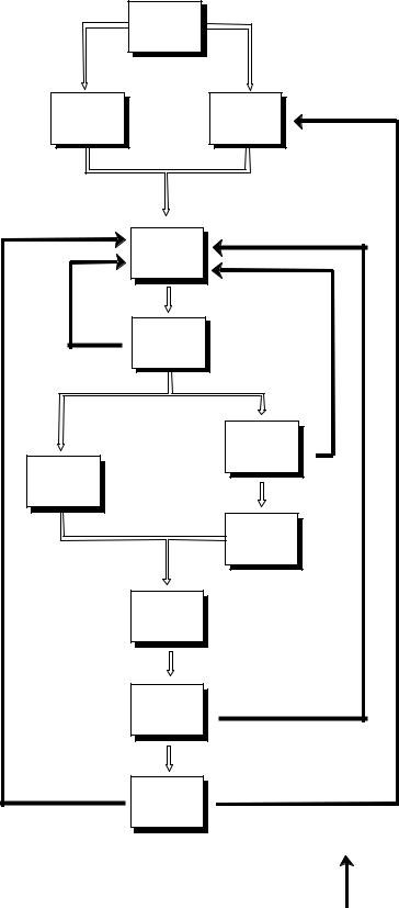
- •Figure 2 LSA Process during equipment design
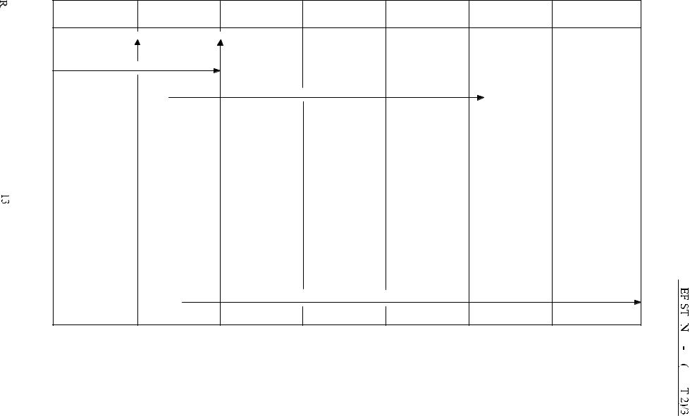
- •Figure 3 Task breakdown for full development project
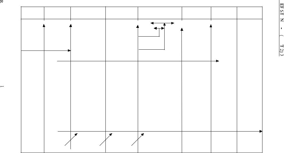
- •Figure 4 Task breakdown for first-of-class warship project
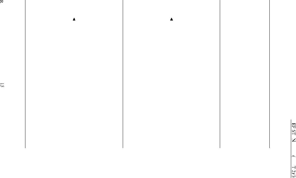
- •Figure 5 Task breakdown for commercial off-the-shelf project
- •Figure 6 Task breakdown for non-developmental project
- •Figure 7 Tailoring logic diagram
- •Figure 8 LSA programme planning, control and verification sub-task dependencies
- •Figure 9 LSA assessment and technical sub-task dependencies
- •Figure 10 Comparison of Functional and Physical Breakdowns
- •Figure 11 Functional LCN breakdown
- •Figure 12 Physical LCN breakdown
- •Figure 13 Functional LCN assignment - classical
- •Figure 14 Physical LCN assignment - classical
- •Figure 15 Physical LCN assignment - modified classical
- •Figure 16 Functional LCN - cross-mapping
- •Figure 17 Physical LCN - cross-mapping
- •Figure 18 ALC Assignment for single configuration equipment
- •Figure 19 ALC & UOC Allocation
- •Figure 20 System level Logistic Support Analysis interfaces
- •Figure 21 LSAR Data Table utilization by equipment breakdown
- •Figure 22 Feasibility study phase LSAR
DEF STAN 00-60 (PART 2)/3
Section Three. Application of LSA and LSAR to Projects
7 LSA Process
7.1The LSA process is applicable through all phases of a project. From a MOD perspective, it commences in the Concept phase, with the consideration of supportability aspects. The results of these considerations are fed into the design process to optimize support. However, not all projects have the freedom to influence the design. In cases where LSA cannot influence the design for supportability, tasks will be tailored to the requirements of the project, possibly limited to identifying and recording the logistic support of an existing design. Even such a reduced LSA should include analysis of the maintenance requirements to provide the necessary data for decision making and for determining the logistic support. The LSA process is iterative and continues to be applied throughout the useful life of the equipment. This process is depicted in Figure 2.
7.2Generally, the LSA process cannot be undertaken to the maximum depth of the equipment breakdown structure in a single stage and analysis to the maximum depth for all items may not be justified in all cases. Usually, the analysis starts with assessment of the functional breakdown to identify the main LSA Candidate Items (CI), then progressively analyzes the support for increasing levels of indenture of the equipment breakdown structure (see clause 7.7.2.2). If significant support cost savings are identified in later analysis by a change that also affects earlier analysis, then the previous work should be reassessed to confirm that it is still valid.
7.3The individual LSA task titles from Part 1 of this Defence Standard are shown in Table 1. The term ‘Responsible Agency’ indicates who could be responsible for initiating action under each task. It is stressed that Table 1 is provided for guidance only and not all tasks and sub-- tasks will be appropriate to all stages of every project. The LSA task responsibilities will be defined in the contract.
7.4Application of LSA to Software. Specific guidance on the application of LSA to Software is provided in Part 3 of this Defence Standard. The data requirements and the LSA tasks and sub tasks for Software have been included in annex C to Part 0 and annex A to Part 1 of this Defence Standard respectively.
7.5Part 1 of this Defence Standard provides a series of LSA tasks and subtasks aligned with typical MOD equipment life-cycles. Figures 3, 4, 5 & 6 provide examples of the appropriate matching between these tasks and life-cycles for a:
(a)Full scale development project.
(b)First of Class Warship project.
(c)COTS project.
(d)NDI project.
10
DEF STAN 00-60 (PART 2)/3
PREPARATORY
STUDIES/
STRATEGIES
STAFF TARGET/ |
SUPPORT/ |
|
REQUIREMENT |
||
MAINTENANCE |
||
AND |
||
CONCEPT |
||
USE STUDY |
||
|
||
|
DESIGN |
|
|
FAILURE MODES |
|
|
EFFECTS AND |
|
|
CRITICALITY |
|
|
ANALYSIS |
|
|
RELIABILITY |
|
|
CENTRED |
|
|
MAINTENANCE |
|
CORRECTIVE |
|
|
MAINTENANCE |
|
|
|
PREVENTATIVE |
|
|
MAINTENANCE |
|
|
SUPPORT |
|
|
RESOURCE |
|
|
REQUIREMENTS |
|
|
LEVEL OF |
|
|
REPAIR |
|
|
ANALYSIS |
|
|
MAINTENANCE |
|
|
PLANS |
|
|
KEY: |
FEEDBACK OF
FEATURES OR
SUPPORT
REQUIREMENTS
Figure 2 LSA Process during equipment design
11
DEF STAN 00-60 (PART 2)/3 |
|
|
|
Table 1 LSA Task Responsibilities |
|
Task No |
Title |
Responsible Agency |
101 |
LSA Strategy |
CUSTOMER |
102 |
LSA Plan |
CONTRACTOR |
103 |
Programme and Design Review |
CUSTOMER & or CONTRACTOR |
201 |
Use Study |
CUSTOMER & or CONTRACTOR |
202 |
Standardization of Hardware, |
|
|
Software and Support |
CUSTOMER & or CONTRACTOR |
203 |
Comparative Analysis |
CUSTOMER & or CONTRACTOR |
204 |
Technological Opportunities |
CUSTOMER & or CONTRACTOR |
205 |
Supportability and |
|
|
Supportability |
|
|
Related Design Factors |
CUSTOMER & or CONTRACTOR |
301 |
Functional Requirements |
|
|
Identification |
CONTRACTOR |
302 |
Support System Alternatives |
CUSTOMER & or CONTRACTOR |
303 |
Evaluation of Alternatives |
|
|
and Trade-off Analysis |
CUSTOMER & or CONTRACTOR |
401 |
Task Analysis |
CONTRACTOR |
402 |
Early Fielding Analysis |
CUSTOMER & or CONTRACTOR |
403 |
Post Production Support |
|
|
Analysis |
CUSTOMER & or CONTRACTOR |
501 |
Supportability, Test |
|
|
Evaluation and Verification |
CUSTOMER & or CONTRACTOR |
7.5.1 Although there are some interdependencies between LSA tasks, Figures 3 to 6 are not intended to imply that the tasks should be completed consecutively.
7.6 The greatest influence of design for supportability is achieved in the Concept, Feasibility and Project Definition (PD) phases. These phases should contain early analysis results including trade-off studies affecting supportability. Identified risk factors that could prejudice the optimum achievement of supportability should be highlighted.
12
CONCEPT |
FEASIBILITY |
PROJECT |
FULL SCALE |
PRODUCTION |
IN-SERVICE |
DISPOSAL |
|
DEFINITION |
DEVELOPMENT |
||||||
|
|
|
|
|
|||
|
ST |
SR |
|
|
|
|
|
|
ILS STRATEGY |
|
|
|
|
|
|
|
|
|
ILS PLAN / ISP |
|
|
|
|
101 |
101 |
101 |
102 |
102 |
501 |
|
|
201 |
102 |
102 |
103 |
103 |
|
|
|
|
103 |
103 |
201 |
402 |
|
|
|
|
201 |
201 |
202 |
403 |
|
|
|
|
203 |
202 |
203 |
501 |
|
|
|
|
204 |
203 |
204 |
|
|
|
|
|
|
204 |
205 |
|
|
|
|
|
|
205 |
301 |
|
|
|
|
|
|
301 |
302 |
|
|
|
|
|
|
|
|
|
|
||
|
|
302 |
303 |
|
|
|
|
|
|
303 |
401 |
|
|
|
|
|
|
|
|
|
|
||
|
|
501 |
501 |
|
|
|
|
|
|
|
|
|
|
||
|
|
|
DEVELOP LSAR / LSAR REPORTS |
|
|
|
Figure 3 Task breakdown for full development project
|
|
PROJECT DEFINITION |
BUILD CONTRACT |
|
|
|
|
||
CONCEPT |
FEASIBILITY |
OUTLINE DESIGN |
DEFINITION |
DETAILED DESIGN & BUILD |
PART IV TRIALS |
IN - SERVICE |
DISPOSAL |
||
|
|
|
|
|
|
|
|||
ST |
|
SR |
|
|
ORDC FOC |
( ACCEPT ) |
ISD |
|
|
|
|
|
|
|
|
|
PAD |
|
|
|
|
|
|
Weapon System(s) |
|
|
|
|
|
|
|
|
|
Installation |
and |
|
|
|
|
|
|
|
|
Integration |
|
|
|
|
|
ILS STRATEGY |
|
|
|
ME Equipment(s) |
|
|
|
|
|
|
|
|
|
Installation |
|
|
|
|
|
|
|
ILS |
PLAN / ISP |
|
|
|
|
|
|
101 |
101 |
|
101 |
101 |
103 |
|
102 |
501 |
|
102 |
102 |
|
102 |
102 |
102 |
|
103 |
|
|
201 |
103 |
|
103 |
103 |
202 |
|
402 |
|
|
|
201 |
|
201 |
201 |
205 |
|
403 |
|
|
|
202 |
|
202 |
202 |
501 |
|
501 |
|
|
|
203 |
|
203 |
203 |
|
|
|
|
|
|
205 |
|
204 |
205 |
|
|
|
|
|
|
|
|
205 |
301 |
|
|
|
|
|
|
|
|
301 |
501 |
|
|
|
|
|
|
|
|
501 |
|
|
|
|
|
|
|
|
|
|
DEVELOP LSAR / LSAR REPORTS |
|
|
|
|
|
|
LSAR DATA FROM LOWER LEVELS |
|
|
|
|
|
|
||
Figure 4 Task breakdown for first-of-class warship project
SELECTION |
|
PRODUCTION |
ACCEPTANCE TESTING |
|
IN - SERVICE |
DISPOSAL |
|
|
|
|
|
|
|
ORDER |
|
|
ACCEPT |
|
||
101 |
102 |
102 |
501 |
|
|
102 |
103 |
103 |
|
|
|
201 |
301 |
401 |
|
|
|
202 |
302 |
402 |
|
|
|
203 |
303 |
501 |
|
|
|
301 |
401 |
|
|
|
|
302 |
403 |
|
|
|
|
303 |
501 |
|
|
|
|
|
|
|
|
|
|
Figure 5 Task breakdown for commercial off-the-shelf project
SELECTION |
DEVELOPMENT |
|
PRODUCTION |
|
IN - SERVICE |
DISPOSAL |
|
|
|
|
|
|
|
|
|
|
|
|
|
|
|
|
|
|
|
|
|
|
ORDER |
ACCEPT |
|
|
|
||
|
|
|
|
|
|
|
|
|
101 |
101 |
102 |
501 |
102 |
102 |
103 |
|
201 |
201 |
301 |
|
202 |
202 |
302 |
|
203 |
203 |
303 |
|
301 |
205 |
402 |
|
302 |
301 |
403 |
|
303 |
302 |
501 |
|
|
303 |
|
|
|
401 |
|
|
|
402 |
|
|
|
403 |
|
|
|
501 |
|
|
Figure 6 Task breakdown for non-developmental project
DEF STAN 00-60 (PART 2)/3
7.7 LSAR Development
7.7.1The population of the LSAR usually commences in PD, or earlier if a Baseline Comparison System (BCS) is used, to record the results generated by conducting LSA. The population and refinement of the LSAR may continue throughout the equipment life cycle.
7.7.2The tailoring of the LSAR is designed to meet the objectives of the LSA programme. The LSAR data created during the procurement process can be used as described in Part 0 of this Defence Standard, for the through-life equipment support management. When initiating the LSAR there are two aspects that must be considered, these are the LSA Control Number (LCN) structure and the LSA Candidate Items List (CIL).
7.7.2.1LCN Structure. The LSAR can contain a substantial amount of data. The method for managing this data (using functional and/or physical breakdown) is through the LCN. This is a unique identifier assigned to at least every Maintenance Significant Item (MSI). The LCN structure should be developed as early as possible and care should be taken to make it flexible. Two methods are commonly used for LCN assignment; classical and modified classical. Guidance on each method is given in annex A.
7.7.2.2LSA CIL. The LSA process should start by identifying those elements of the equipment that are candidates for analysis. The LSA CIL identifies each part of the equipment that should be considered for further analysis through the performance of LSA tasks. The primary source for the identification of MSI is the Failure Mode Effects and Criticality Analysis (FMECA) process. As the analysis proceeds, the preliminary candidate list is extended as lower level assemblies and items are identified through further analysis. Eventually every item in the equipment that requires support activity, or is involved with the operation of the equipment, may be considered as a candidate. Piece parts and materials used to manufacture items are not normally included in the CIL. CI identified as being nonsignificant as a result of analysis will be removed from the CIL.
7.7.2.3LSA candidates should not be limited to just the equipment MSI but should include support, test and training equipment; consideration may also be given to transportation, storage, packaging and handling, supply support and facilities. The CIL is maintained and updated throughout the LSA programme and becomes a guide for ensuring that all support significant items in the equipment are properly addressed by the LSA process.
7.8 Maintenance Planning
7.8.1As stated in Part 0 of this Defence Standard, maintenance planning is a principal ILS element. The maintenance plan is developed from the LSA process. This process may include the application of Failure Modes and Effects Analysis (FMEA)/FMECA, ReliabilityCentred Maintenance (RCM) and Level Of Repair Analysis (LORA) techniques together with task analysis (LSA Task 401). Where appropriate software support analysis should be applied as described in Part 3 of this Defence Standard.
7.8.2Task analysis will be carried out to a level and depth commensurate with the type of project procurement and the project phase in the life-cycle. For a project undergoing design
17
