

Сборник трудов конференции СПбГАСУ 2014 ч
.1.pdfРаздел 3. Аналитические и численные методы исследований оснований и фундаментов
элементов может быть различной: треугольной или четырехугольной для плоских задач, в виде тетраэдра или параллелепипеда для пространственных задач.
Потенциальная энергия тела Э суммируется из потенциальных энергий отдельных его элементов:
Э k U |
i |
|
k |
A |
|
t A |
p |
|
(9) |
|
|
|
|
i |
|
i |
|
||
i 1 |
|
|
i 1 |
|
|
i 1 |
|
|
|
Ui – потенциальная энергия деформации; |
А i |
|
– работа объемных сил; |
||||||
Ap i – работа поверхностных сил; |
к – количество элементов внутри тела; |
||||||||
t – количество элементов на нагруженной части поверхности тела.
Вдальнейшем, в качестве поверхностных сил, рассматривается равномерно распределенная нормальная к поверхности тела нагрузка интенсивно-
сти q0, в качестве объемных сил – собственный вес, через γ – обозначается объемный вес материала тела.
Вкаждом «n»-ом приближении метода упругих решений определяется значение полной потенциальной энергии тела Эn . Критерием сходимости
решения является энергетический принцип, согласно которому в равновесном состоянии Э Эmin [3]. Вариационное уравнение Э 0 , в интегральной
форме выражающее условия равновесия деформированного тела, эквивалентно и включает в себя дифференциальные уравнения равновесия вместе с условиями равновесия на поверхности тела (граничными условиями). В качестве независимых варьируемых параметров берутся переменные парамет-
ры упругости E*, *,G*, напряжения и деформации связаны с ними зависи-
мостями (4) или (5). Составляющие перемещений в направлении осей x,y,z связаны с деформациями на базе зависимостей Коши [3]. Эти условия выражают непрерывность и совместность деформаций. Используя уравнения состояний (1) или (2), во всех точках тела варьируются компоненты напряжений и, соответственно, компоненты деформаций и перемещений и. Перебрав , , и во всех выбранных точках тела, получаем новое состояние. Возможность этого состояния определяется функционалом полной потенциальной энергии тела.
В каждом приближении напряжения и деформации варьируются только во внутренних точках тела (в узлах элементов). На наружной и внутренней поверхностях грунтового массива напряжения и деформации не варьируются, т.к. в этих точках должны удовлетворяться статические (на наружной поверхности при z=0) и кинематические условия (при z=H перемещения равны нулю). В качестве нулевого приближения для нелинейного решения и при учете ползучести грунта берется линейное решение. Используя разбиение грунтового массива на отдельные элементы в виде тетраэдра или параллелепипеда для трехмерной задачи и прямоугольных элементов для плоской за-
541

Современные геотехнологии в строительстве и их научно-техническое сопровождение
дачи, в каждой узловой точке определяются все необходимые компоненты напряжений и деформаций в нулевом приближении и значение полной потенциальной энергии массива. Далее начинается процедура приближений с помощью вариаций компонентов напряжений и связанных с ними компонентов деформаций в каждой узловой точке. Как было ранее сказано, нулевое приближение соответствует линейному решению, при этом полная энергия системы равна Э0 , в каждом последующем приближении минимизируется Э
путем вариаций напряжений и деформаций во всех узловых точках. Получается последовательность значений энергии Э0, Э1,…Эn. Таким образом задача сводится к вариационному исчислению,т. е. определению предела последовательности Эi.
Для каждого элемента находим значения напряжений , деформаций, перемещений и во всех узлах. Перебрав все точки, получаем решение, т. е. новое приближение и соответствующее ему значение полной энергии тела в этом состоянии. Сравнивая энергию с предыдущим и последующим состояниями, можно сделать оценку: является ли это состояние равновесным, и есть ли необходимость в дальнейших вариациях. Данный алгоритм позволяет решать линейную (упругую) задачу, нелинейную задачу, а также учитывать скорость деформаций i , т. е. рассматривать процесс во времени. Нели-
нейное решение без учета i получается из вышеописанного алгоритма, полагая в уравнениях состояния i =0 [2]. Рассматривая непрерывный процесс
деформирования во времени, можно решать задачи с переменными скоростями напряжений и деформаций по суткам, месяцам и годам. На печать можно выдавать результаты в интересующие моменты времени или конечные результаты за период времени Т. Для реализации данного алгоритма составлена программа на ПК. Осадки грунтового массива вычисляются в каждой точке поверхности с координатами xi, yi путем интегрирования по толщине массива, т. е. при численном расчете осадки определяются по следующей формуле:
s
w( xi , yi ) w( xi , yi , z j )
j 1
s – количество элементов по толщине массива в каждой «i» точке. Эти значения осадок являются элементами полного вектора перемещений вдоль оси z ,
т. е. W (w1 , w2 ,...wk ) ,
k – количество фиксированных точек на внешней поверхности массива. При рассмотрении процесса деформирования во времени учитывается,
что скорость интенсивности деформаций можно представить в конечноразностном виде. В данной работе величина i задаваема и постоянна:
542

Раздел 3. Аналитические и численные методы исследований оснований и фундаментов
|
|
i |
|
i k 1 |
i k |
, |
(10) |
|
|
|
|
t |
|
|
|
где t tk 1 |
tk , |
i k 1 - интенсивность деформации в «к+1»-й момент вре- |
|||||
мени; i k |
– интенсивность деформации в «к»-ый момент времени. |
|
|||||
Используя итерации по времени t, можно выразить интенсивность деформации в «к+1»-й момент времени через интенсивность деформаций в предыдущий, т. е. в «к»-й момент времени. Рассматривая процесс за про-
межуток времени Т, можно разбить его на отдельные интервалы по t Tn ,
где n – целое число. На основе итерации по t на каждом интервале t удаётся получить полную картину напряженно-деформированного состояния (НДС) в соответствии с вышеописанным алгоритмом.
Врезультате расчета можно получить картину изменения НДС грунтового массива в зависимости от типа грунтов, скоростных факторов деформирования и нагружения, интенсивности приложенной на поверхности нагруз-
ки [4–5].
Втабл. 1 приведены значения прогиба в центре дорожных и фундаментных плит для 3-х указанных случаев при двух значениях нагрузки q. Учет ползучести основания представлен для двух моментов времени: t=1 год;
t= |
|
5 лет при |
постоянной скорости интенсивности |
деформации |
||||||
|
10 |
7 |
% / час. |
|
|
|
|
|
|
|
i |
|
|
|
|
|
|
|
|||
|
|
|
|
Значения прогиба в центре плиты w 10-2 см |
|
Таблица 1 |
||||
|
|
|
|
|
|
|||||
|
|
Размеры плиты |
Нагрузка q |
Линейное |
Нелинейное |
Ползучесть |
|
Ползучесть |
||
|
|
|
|
|
[МПа] |
решение |
решение |
t=1год |
|
t=5 лет |
|
|
3 3м (h=0,1м) |
0,01 |
0,85 |
2,52 |
1,5 |
|
1,82 |
||
|
|
|
|
|
0,02 |
1,61 |
5,25 |
4,23 |
|
4,33 |
|
|
18 18м (h=0,3м) |
0,01 |
3,25 |
10,24 |
5,12 |
|
5,16 |
||
|
|
|
|
|
0,02 |
9,78 |
27,34 |
12,76 |
|
12,8 |
|
|
24 24м (h=0,4м) |
0,01 |
5,04 |
14,13 |
6,54 |
|
6,59 |
||
|
|
|
|
|
0,02 |
13,12 |
36,73 |
16,43 |
|
16,53 |
Выводы
1.Прогибы плиты, лежащей на упругом основании, отличаются от случая нелинейно деформируемого основания. Наибольшие прогибы соответствуют нелинейному основанию, с учетом реологических свойств грунта значения прогиба плиты уменьшаются на 30–40 %.
2.В связи с малым значением скорости интенсивности деформации грунтового основания прогибы плиты медленно возрастают во времени, это указывает на стабилизацию процесса деформации основания.
3.Результаты численного расчета очень важны для прогноза ожидаемых деформаций фундаментных и дорожных плит. Осадки в начальный пе-
543

Современные геотехнологии в строительстве и их научно-техническое сопровождение
риод интенсивно нарастают, затем скорость их изменения уменьшается и в пределе эта скорость стремится к нулю, что указывает на стабилизацию процесса во времени. Стабилизация наступает быстрее при больших скоростях деформаций, при малых значениях наблюдается медленная ползучесть.
Литература
1.Горбунов-Посадов М.И., Маликова Т.А., Соломин В.И. Расчет конструкций на упругом основании, Москва, Стройиздат, 1984, 679с.
2.Исаханов Е.А. Реологические свойства плотных глинистых грунтов и расчеты сооружений, Алматы,2000, 144с.
3.Александров А.В., Потапов В.Д. Основы теории упругости и пластичности, Москва, Высшая школа, 1990, 400с
4.Исаханов Е.А., Достанова С.Х., Токпанова К.Е. Напряженно-деформированное состояние плит с учетом деформируемости грунтового основания. Материалы Международной научно-технической конференции «Современные проблемы геотехники, механики
истроительства транспортных сооружений».- Алматы, КазАТК, 2010.- С. 112-115.
5.Исаханов Е.А., Токпанова К.Е. Расчет аэродромных и дорожных покрытий методом прямых вариаций.- Алматы, КазАТК, 2007.-153с.
УДК 627.8.04
T. Tanaka (University of Tokyo, Tokyo, Japan),
A. Zhussupbekov, A. Aldungarova
(L.N. Gumiylev Eurasian National University, Astana, Kazakhstan)
PHYSICAL SIMULATION OF INTERACTION EARTH DAMS WITH UNDERMINING TERRITORIES AND SEISMIC ZONE
The article describes a technique of physical modeling of groundwater dam on moonlighting basis method of equivalent materials for large-scale laboratory bench with layering body embankment reinforced and unreinforced ways
Introduction. During the construction and operation of buildings and structures on undermined territories danger significant movement of foundations, which can lead to damage and even destruction of supporting structures. Currently adequately developed methods of calculation and simulation of various types of foundations (belt, bar, pile) buildings on undermined territories [1]. However, their practical use for the analysis of dams in such areas needs further validation and study. This is due mainly to the need to consider the additional stress field arising in the base and the body of the dam at undermining the territory or seismic zone in which it is located.
The aim of this work is to develop methods of physical modeling of the stress – strain state of dams in different variants arising during deformation of the undermining territory or seismic zone.
544

Раздел 3. Аналитические и численные методы исследований оснований и фундаментов
Modeling method. To achieve the goal of research the method of equivalent materials includes in [2]. This method is not associated with the use of expensive equipment, simple, convenient and offers a wealth of scientific information required in a relatively short time compared with the field the same tests. Using this method of modeling is justified by the fact that under the requirements of the theory of similarity, we can obtaine not only qualitative relations, but also some quantitative data that will need to be confirmed by field experiments or modern theoretical methods. Complement physical modeling results of theoretical studies, such as finite element analysis, makes it possible to verify the adequacy of the design model of the dam and foundation in the development of the project and, if necessary, to clarify the scheme and reinforcement parameters mound.
Stand scheme. Stand for simulation (volumetric) deformation model dirt dam (Fig. 1) is in the form of individual sections of channel 1. Between sections 1 fitted elastic rubber gaskets 2 – 10 mm thick. Side shelves stocked trough sections 1 bolting 3 in the upper and lower levels horizontally. The tray has end walls 4. The lower part of channel section 1 is provided with adjustable feet 5 , made in the form of ball bearings mounted on the support frame 6 (Fig. 2) . Stand size is 1600 x 1000 x 250 mm. The design of the stand allows surround a considerable range to create independent tensile strain and curvature, as well as to vary the size of the dam model 7. Choosing the right size based on the results of preliminary calculations. Testing is as follows: using bolting 3 produce compression or stretching of channel sections 1, with whom deformed material in the tray. Horizontal tensile strain ground forces provided by elastic recovery of compressed elastic (rubber) gaskets 2 when loosening of bolted joints 3. Horizontal compressive strain soil provides compression elastic (rubber) gaskets 2 by bolting 3, bring together the sections of channel model 1. Precipitation models mound measured deflectometer, moving the soil surface fixed dial gauge. Horizontal deformation of the base in the process of earning a micrometer determined by measuring the distance between the marks .
Selection of equivalent materials. According to the method of equivalent materials proposed G.N. Kuznetsov [2], according to the characteristics of the mechanical properties and the full-scale model of soil NH and NM can be for a given relationship γM/γН and relationships NM/NH calculate the scale of the model. As determined by the physical and mechanical characteristics are taken those characteristics that play in the process leading role. In the selection of materials – equivalent granular soils can, to a first approximation, as the defining characteristics of the clutch and use the values of the angle of internal friction C, φ. To ensure similarity conditions fracture processes here should respect the equality (1):
Cm I |
L |
М |
CН ; |
(1) |
|
|
Н |
|
|
tg m tg н , |
(2) |
|||
545

Современные геотехнологии в строительстве и их научно-техническое сопровождение
were I / L mt - linear scale model; M , N – angles of internal friction of material models and nature; CM ,CN – coefficients of cohesion of model and the real soil ground.
a)
3 |
|
1 |
|
А |
А |
|
5 |
6 |
|
b)
А - А
7
Figure 1. Stand for research of behaviour of model dirt dam: a – side view, b – top view with model of ground dam
When modeling of cohesive soils according to equivalent material, to establish the scale model, you must define the following physical characteristics of the sand mixture: a, φ, E, γ. Below are examples of data on the selection of the material equivalent to the dam of the loam with physicalmechanical characteristics shown in Table 1. Scale Models – 1/40. Subgrade material model takes a mixture consisting of 97% fine quartz sand and 3% by weight of the spindle oil having a grip that allows modeling of cohesive soils. The results of the selection of the model parameters shown in Table 2.
546
Раздел 3. Аналитические и численные методы исследований оснований и фундаментов
|
|
|
|
|
|
|
|
|
|
|
|
|
|
|
Table 1 |
|
|
|
|
|
Physical and mechanical parameters of the soils of nature dam |
||||||||||||
|
Type of |
|
Specific |
|
Cohesion |
|
Angle of internal |
Modulus of |
|
Poisson's |
||||||
|
soil |
|
gravity, |
|
С, (kPa) |
|
|
friction, (deg) |
deformation, |
|
ratio |
|||||
|
|
|
γ (kN/m3) |
|
|
|
|
|
|
|
Е (MPa) |
|
|
|||
|
Loam |
|
20,5 |
|
40 |
|
22 |
|
20 |
|
|
0,3 |
|
|||
|
|
|
|
|
|
|
|
|
|
|
|
|
|
|
Table 2 |
|
|
|
Physical and mechanical parameters of the soils of model dam |
||||||||||||||
|
Type of soil |
|
Specific |
|
Cohesion |
|
Angle of |
|
Modulus of |
|
Poisson's ratio |
|
||||
|
|
|
|
gravity, |
|
С, (kPa) |
|
internal |
|
deformation, |
|
|
|
|||
|
|
|
|
γ (kN/m3) |
|
|
|
|
friction, |
|
Е (MPa) |
|
|
|
|
|
|
|
|
|
|
|
|
|
|
|
(deg) |
|
|
|
|
|
|
|
Sand - 97% + |
|
17,0 |
|
|
0,90 |
|
|
39 |
|
0,27 |
|
0,25 |
|
||
|
3% - spindle |
|
|
|
|
|
|
|
|
|
|
|
|
|
|
|
|
oil |
|
|
|
|
|
|
|
|
|
|
|
|
|
|
|
Preparing a dam. Preparing a dam without reinforcement is accomplished by layering (5 cm to 8 layers) with tamper roller (Fig. 2).
500
300
400
Figure 2. A general model of the dam
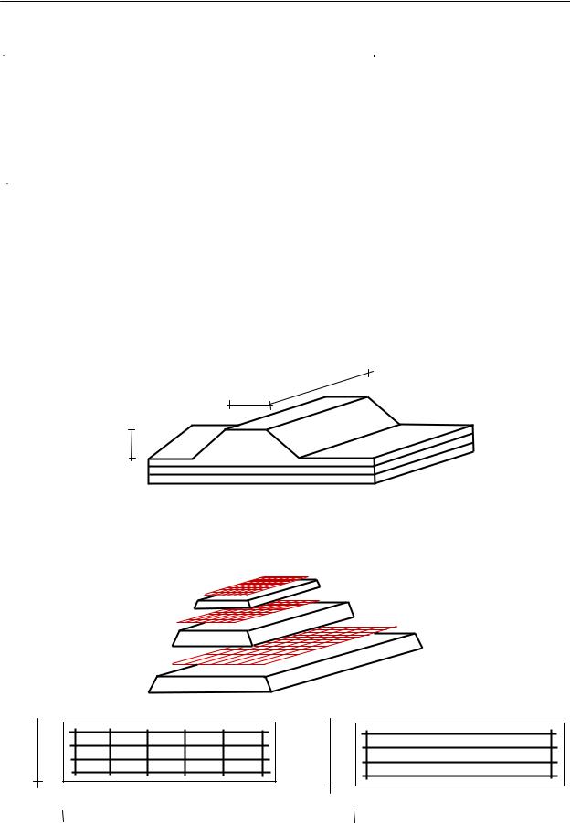
Circuit training model mound of soil layers with reinforcement is shown in Figure 3.
a)
380
350
320
b)
380
350
320
580, 550, 520 |
|
|
580, 550, 520 |
|
|
|
|
|
|
|
|
|
|
|
|
|
|
|
|
Figure 3. Schematic model of the dam reinforcement:
a – the general scheme of reinforcement, b – options reinforced grids
547
Раздел 3. Аналитические и численные методы исследований оснований и фундаментов
Figure 6
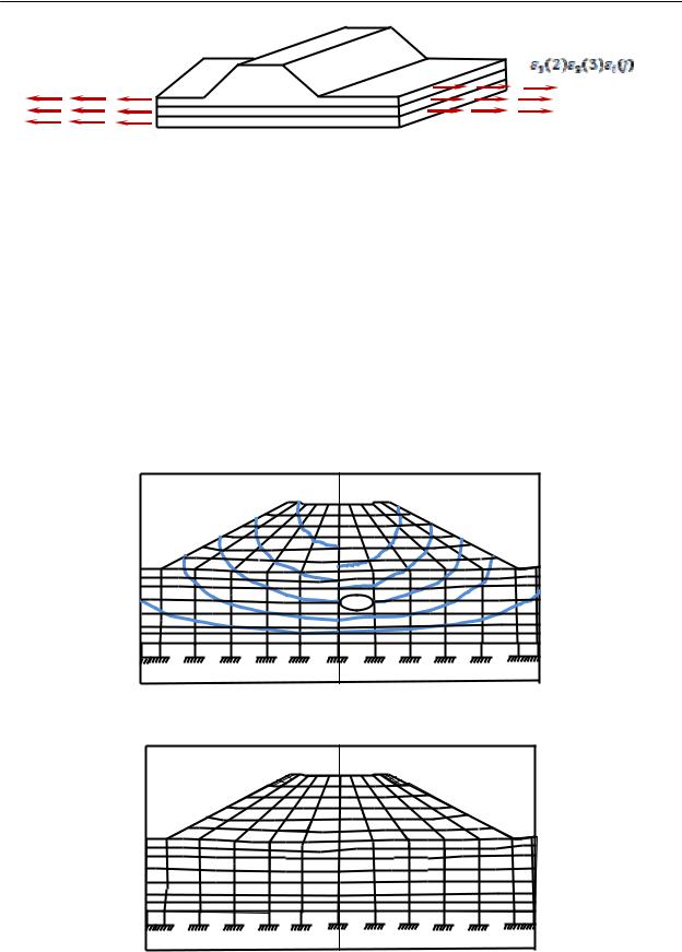
Numerical evaluation of the impact of part-time work on the territory of the stress-strain state of the dam. Consider the results of the performed numerical calculations of the stress-strain state of the dam height of 12 m using finite element method (FEM). The calculations are performed on the program of Prof. T.Tanaka [3] with using elastic-perfectly-plastic model of soil deformation under the scheme shown in Fig. 4. Data on the physical and mechanical properties of the soil are given in Table 1.
Figure 7 shows the contours of vertical displacements of the points of the dam, and Figure 8 – zone limit state in a mound of soil at various circuits horizontal deformation of foundation: a – in the absence of pre-deformation, b – under the
influence of pre-strain ε= 6 10-3. |
b) |
0.150 |
Figure 7. Contours of vertical displacements of the dam |
Figure 8. Develop zones limiting condition of soils in embankment
549

Современные геотехнологии в строительстве и их научно-техническое сопровождение
Their analysis shows that the pre-deformation of the base of the dam generated when undermined territory, has a significant impact on its stress-strain state.
Conclusion
1.Designed and manufactured construction laboratory bench allows for physical modeling of dams on undermined territories with different variants of deformation of their bases.
2.According to the results of numerical calculations confirmed the need for comprehensive studies of dams on undermined territories using the methods of the physical and mathematical modeling.
References
1 Жусупбеков А.Ж. Строительные свойства оснований фундаментов сооружений на подрабатываемых территориях – Алматы: Гылым, 1994. – 162 с.
2Моделирование проявлений горного давления / Г.Н. Кузнецов, М.Н. Будько, Ю.И. Васильев и др. – Л.:Недра, 1968. –280 с.
3Tanaka T., Zhussupbekov A., Okajima K., L.N. Gumilev The estimation of conditions of sheet piles and strut in the excavation work using sheet pile by Elasto-Plastic FEM/Сборник трудов научно-технической конференции: Актуальные вопросы геотехники при решении сложных задач нового строительства и реконструкции, Санкт-Петербург, 2010.- с.149-157.
УДК 624.151
S. Varaksin (Paris, ISSMGE TC21), Hamidi Curtin B. (University Perth, Australia)
CONTRIBUTIONS OF THE PRESSUREMETER TO GROUND IMPROVEMENT AND PERSPECTIVES FOR THE FUTURE
Abstract
Menard not only developed the pressuremeter as an industrial tool for measuring ground characteristics, but also introduced a new approach to directly utilize the measured values to calculate bearing capacity and ground deformations without the commonly implemented classical parameters and failure criteria. The pressuremeter has also proven to be a very precious tool for verification and evaluation of ground improvement results, and has more recently contributed to providing parameters for the increasingly popular numerical analyses approaches. In this paper, the authors will review the history of the pressuremeter test and its application in ground improvement projects.
1. Introduction
Louis Ménard was born on 4 May 1931 in the Bay of Mont-Saint-Michel, France. He attended the civil engineering school of the prestigious École des Ponts et Chaussées in 1952. During the summer that he was employed to carry out com-
550

Современные геотехнологии в строительстве и их научно-техническое сопровождение
Their analysis shows that the pre-deformation of the base of the dam generated when undermined territory, has a significant impact on its stress-strain state.
Conclusion
1.Designed and manufactured construction laboratory bench allows for physical modeling of dams on undermined territories with different variants of deformation of their bases.
2.According to the results of numerical calculations confirmed the need for comprehensive studies of dams on undermined territories using the methods of the physical and mathematical modeling.
References
1 Жусупбеков А.Ж. Строительные свойства оснований фундаментов сооружений на подрабатываемых территориях – Алматы: Гылым, 1994. – 162 с.
2 Моделирование проявлений горного давления / Г.Н. Кузнецов, М.Н. Будько, Ю.И. Васильев и др. – Л.:Недра, 1968. –280 с.
3 Tanaka T., Zhussupbekov A., Okajima K., L.N. Gumilev The estimation of conditions of sheet piles and strut in the excavation work using sheet pile by Elasto-Plastic FEM/Сборник трудов научно-технической конференции: Актуальные вопросы геотехники при решении сложных задач нового строительства и реконструкции, Санкт-Петербург, 2010.- с.149-157.
УДК 624.151
S. Varaksin (Paris, ISSMGE TC21), Hamidi Curtin B. (University, Perth, Australia)
CONTRIBUTIONS OF THE PRESSUREMETER TO GROUND IMPROVEMENT AND PERSPECTIVES FOR THE FUTURE
Abstract
Menard not only developed the pressuremeter as an industrial tool for measuring ground characteristics, but also introduced a new approach to directly utilize the measured values to calculate bearing capacity and ground deformations without the commonly implemented classical parameters and failure criteria. The pressuremeter has also proven to be a very precious tool for verification and evaluation of ground improvement results, and has more recently contributed to providing parameters for the increasingly popular numerical analyses approaches. In this paper, the authors will review the history of the pressuremeter test and its application in ground improvement projects.
1. Introduction
Louis Ménard was born on 4 May 1931 in the Bay of Mont-Saint-Michel, France. He attended the civil engineering school of the prestigious École des Ponts et Chaussées in 1952. During the summer that he was employed to carry out com-
550