

Параллельные Процессы и Параллельное Программирование / SNNSv4.2.Manual
.pdf4.3. WINDOWS OF XGUI |
39 |
Graph display, to explain the network error during teaching graphically.
Class panel to control the composition of the training pattern le.
Bignet panel to facilitate the creation of big regular networks.
Pruning panel for control of the pruning algorithm.
learning.Cascade panel for control of the learning phase of cascade correlation and TACOMA
Kohonen panel, an extension to the control panel for Kohonen networks.
Weight Display, to show the weight matrix as a WVor Hinton diagram.
Projection panel to clarify the in uence of two units onto a third one.
Analyzer for supervising recurrent (and other) networks.
Inversion display, to control the inversion method network analysing tool.
Print panel to generate a Postscript picture of one of the 2D displays.
Help windows to display the help text.
Of these windows only the Manager panel and possibly one or more 2D displays are open from the start, the other windows are opened with the corresponding buttons in the manager panel or by giving the corresponding key code while the mouse pointer is in one of the SNNS windows.
Additionally, there are several popup windows (transient shells) which only become visible when called and block all other XGUI windows. Among them are various Setup panels for adjustments of the graphical representation. (called with the button SETUP in the various windows)
There are a number of other popup windows which are invoked by pressing a button in one of the main windows or choosing a menu.
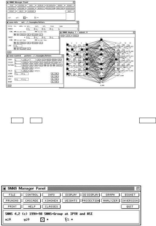
Figure 4.7 shows a typical screen setup. The Manager panel contains buttons to call all other windows of the interface and displays the status of SNNS. It should therefore always be kept visible.
The Info panel displays the attributes of two units and the data of the link between them. All attributes may also be changed here. The data displayed here is important for many editor commands.
In each of the Displays a part of the network is displayed, while all settings can be changed using Setup. These windows also allow access to the network editor using the keyboard (see also chapter 6).
The Control panel controls the simulator operations during learning and recall.
In the File panel a log le can be speci ed, where all XGUI output to stdout is copied to. A variety of data about the network can be displayed here. Also a record is kept on the load and save of les and on the teaching.
40 |
CHAPTER 4. USING THE GRAPHICAL USER INTERFACE |
Figure 4.7: Manager panel, info panel, control panel and a display.
The complete help text from the le help.hdoc is available in the text section of a help window. Information about a word can be retrieved by marking that word in the text and then clicking LOOK or MORE . A list of keywords can be obtained by a click to TOPICS . This window also allows context sensitive help, when the editor is used with the keyboard.
QUIT is used to leave XGUI. XGUI can also be left by pressing ALT-q in any SNNS window. Pressing ALT-Q will exit SNNS without asking further questions.
4.3.1Manager Panel
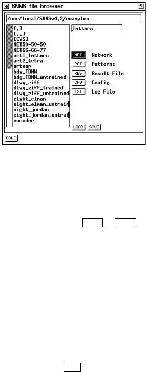
Figure 4.8 shows the manager panel. From the manager panel all other elements that have a di erent, independent window assigned can be called. Because this window is of such central importance, it is recommended to keep it visible all the time.
Figure 4.8: Manager panel
The user can request several displays or help windows, but only one control panel or text window. The windows called from the manager panel may also be called via key codes as follows (`Alt-' meaning the alternate key in conjunction with some other key).
4.3. WINDOWS OF XGUI |
|
|
41 |
|
|
|
|
|
|
|
FILE |
Alt-f |
CONTROL |
Alt-c |
|
|
|
|
|
|
INFO |
Alt-i |
DISPLAY |
Alt-d |
|
|
|
|
|
|
3D DISPLAY |
Alt-3 |
GRAPH |
Alt-g |
|
|
|
|
|
|
BIGNET |
Alt-b |
PRUNING |
|
|
|
|
|
|
|
CASCADE |
|
KOHONEN |
Alt-k |
|
|
|
|
|
|
WEIGHTS |
Alt-w |
PROJECTION |
Alt-p |
|
|
|
|
|
|
ANALYZER |
Alt-a |
INVERSION |
|
|
|
|
|
|
|
|
HELP |
Alt-h |
|
|
|
|
|
|
|
CLASSES |
|
QUIT |
Alt-q |
|
|
|
|
|
Below the buttons to open the SNNS windows are two lines that display the current status of the simulator.
SNNS Status Message:
This line features messages about a current operation or its termination. It is also the place of the command sequence display of the graphical network editor. When the command is activated, a message about the execution of the command is displayed. For a listing of the command sequences see chapter 6.
Status line:
This line shows the current position of the mouse in a display, the number of selected units, and the position of ags, set by the editor.
X:0 Y:0 gives the current position of the mouse in the display in SNNS unit coordinates.
The next icon shows a small selected unit. The corresponding value is the number of currently selected units. This is important, because there might be selected units not visible in the displays. The selection of units a ects only editor operations (see chapter 6 and 6.3).
The last icon shows a miniature ag. If safe appears next to the icon, the safety ag was set by the user (see chapter 6). In this case XGUI forces the user to con rm any delete actions.
4.3.2File Browser
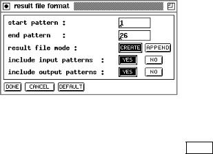
The le browser handles all load and save operations of networks, patterns, con gurations, and the contents of the text window. Con gurations include number, location and dimension of the displays as well as their setup values and the name of the layers.
In the top line, the path (without trailing slash) where the les are located is entered. This can be done either manually, or by double{clicking on the list of les and directories in the box on the left. A double click to [..] deletes the last part of the path, and a double click to a subdirectory appends that directory to the path. In the input eld below the path eld, the name for the desired le (without extension) is entered. Again, this can be done either manually, or by double{clicking on the list of les in the box on the left. Whether a pattern le, network le, or other le is loaded/saved depends on the settings
42 |
CHAPTER 4. USING THE GRAPHICAL USER INTERFACE |
Figure 4.9: File Panel.
of the corresponding buttons below. With the setting of picture 4.9 a network le would be selected. A le name beginning with a slash (/) is taken to be an absolute path.
Note: The extension .net for nets, .pat for patterns, .cfg for con gurations, and .txt for texts is added automatically and must not be speci ed. After the name is speci ed the desired operation is selected by clicking either LOAD or SAVE . In the case of an error the con rmer appears with an appropriate message. These errors might be:
Load: The le does not exist or has the wrong type
Save: A le with that name already exists
Depending upon the error and the response to the con rmer, the action is aborted or executed anyway.
NOTE: The directories must be executable in order to be processed properly by the program!
4.3.2.1Loading and Saving Networks
If the user wants to load a network which is to replace the net in main memory, the con rmer appears with the remark that the current network would be erased upon loading. If the question 'Load?' is answered with YES , the new network is loaded. The le name of the network loaded last appears in the window title of the manager panel.
Note 1: Upon saving the net, the kernel compacts its internal data structures if the units are not numbered consecutively. This happens if units are deleted during the creation of the network. All earlier listings with unit numbers then become invalid. The user is therefore advised to save and reload the network after creation, before continuing the work.
4.3. WINDOWS OF XGUI |
43 |
Note 2: The assignment of patterns to input or output units may be changed after a network save, if an input or output unit is deleted and is inserted again. This happens because the activation values in the pattern le are assigned to units in ascending order of the unit number. However, this order is no longer the same because the new input or output units may have been assigned higher unit numbers than the existing input or output units. So some components of the patterns may be assigned incorrectly.
4.3.2.2Loading and Saving Patterns
Patterns are combinations of activations of input or output units. Pattern les, like nets, are handled by the SNNS kernel. Upon loading the patterns, it is not checked whether the patterns t to the network. If the number of activation values does not t to the number of input, resp. output units, a sub-pattern shifting scheme has to be de ned later on in the sub-pattern panel. See chapter 5 for details. The lename of the patterns loaded last is displayed in the control panel.
Note: The activation values are read and assigned to the input and output units sequentially in ascending order of the unit numbers (see above).
4.3.2.3Loading and Saving Con gurations
A con guration contains the location and size of all displays with all setup parameters and the names of the various layers. This information can be loaded and saved separately, since it is independent from the networks. Thereby it is possible to de ne one con guration for several networks, as well as several con gurations for the same net. When xgui is started, the le default.cfg is loaded automatically if no other con guration le is speci ed on the command line.
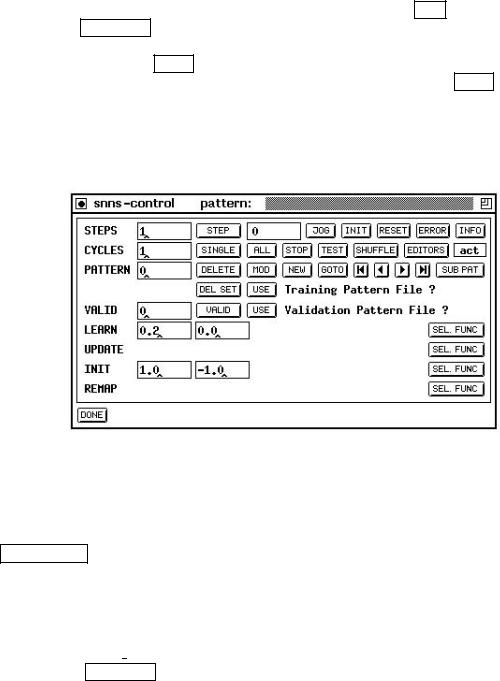
4.3.2.4Saving a Result le
Figure 4.10: Result File Popup
A result le contains the activations of all output units. These activations are obtained by performing one pass of forward propagation. After pressing the SAVE button a popup window lets the user select which patterns are to be tested and which patterns are to be saved in addition to the test output. Picture 4.10 shows that popup window. Since
44 |
CHAPTER 4. USING THE GRAPHICAL USER INTERFACE |
the result le has no meaning for the loaded network a load operation is not useful and therefore not supported.
4.3.2.5De ning the Log File
Messages that document the simulation run can be stored in the log le. The protocol contains le operations, de nitions of values set by clicking the SET button in the info panel or the SET FUNC button in the control panel, as well as a teaching protocol (cycles, parameters, errors). In addition, the user can output data about the network to the logle with the help of the INFO button in the control panel. If no log le is loaded, output takes place only on stdout. If no le name is speci ed when clicking LOAD , a possibly open log le is closed and further output is restricted to stdout.
4.3.3Control Panel
Figure 4.11: Control Panel
With this window the simulator is operated. Figure 4.11 shows this window. Table 4.1 lists all the input options with types and value ranges. The meaning of the learning, update, initialization, and remapping parameters depends upon the functions selected from the SEL. FUNC menu buttons.
The following pages describe the various text elds, buttons and menu buttons of this panel row by row starting in the upper left corner:
1.STEPS: This text eld speci es the number of update steps of the network. With Topological Order selected as update function (chosen with the menu from the button SEL FUNC in the update line of the control panel) one step is su cient to propagate information from input to output. With other update modes or with recursive networks, several steps might be needed.
4.3. WINDOWS OF XGUI |
|
|
45 |
||
|
|
|
|
|
|
|
Name |
Type |
Value Range |
|
|
|
|
|
|
|
|
|
STEPS (update-Steps) |
Text |
0 |
n |
|
|
COUNT (counter for steps) |
Label |
0 |
n |
|
|
CYCLES |
Text |
0 |
n |
|
|
PATTERN (number of current pattern) |
Label |
0 |
n |
|
|
VALID |
Text |
0 |
n |
|
|
LEARN (up to 5 parameters: , , d, . . . ) |
Text |
oat |
|
|
|
UPDATE (up to 5 parameters) |
Text |
oat |
|
|
|
INIT (up to 5 parameters) |
Text |
oat |
|
|
|
REMAP (up to 5 parameters) |
Text |
oat |
|
|
Table 4.1: Input elds of the control panel
2.STEP : When clicking this button, the simulator kernel executes the number of steps speci ed in the text eld STEPS. If STEPS is zero, the units are only redrawn. The update mode selected with the button MODE is used (see chapter 3.2). The rst update step in the mode topological takes longer than the following, because the net is sorted topologically rst. Then all units are redrawn.
3.COUNT: The text eld next to the STEP button displays the steps executed so far.
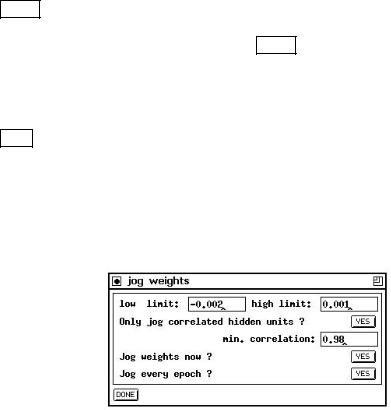
4.JOG : pops up a window to specify the value range (low limit .. high limit) of some random noise to be added to all links in the network. \Low limit" and \high limit" de ne the range of a random fraction of the current link weights. This individual fraction is used as a noise amount. For the given example in gure 4.12
every link changes its weight within the range of [-0.2% 0.1%] of its original value. We found that this often improves the performance of a network, since it helps to avoid local minima.
Figure 4.12: The jog-weights panel
Note, that when the same value is given for upper and lower limit, then the weights will be modi ed by exactly this amount. This means that specifying 1.0/1.0 will add 100% to the link weighs, i.e. doubbling them, while specifying -1.0/-1.0 will subtract 100% from each link weight, i.e. setting all the weights to 0.0.
When clicking the YES-button behind the question \Jog weights now ?" the noise is applied to all link weights only once. When clicking the YES-button behind the question \Jog every epoch ?" this noise will be added during training at the

46 |
|
CHAPTER 4. USING THE GRAPHICAL USER INTERFACE |
beginning of every single epoch. To remind you that jogging weights is activated, |
||
the |
JOG |
button will be displayed inverted as long as this option is enabled. |
It is also possible to jog only the weights of highly correlated non-special hidden units of a network by selecting the corresponding button in the panel. For a detailed description of this process please refer to the description of the function jogCorrWeights in chapter 12.
5.INIT : Initialises the network with values according to the function and parameters given in the initialization line of the panel.
6.RESET : The counter is reset and the units are assigned their initial activation.
7.ERROR : By pressing the error button in the control panel, SNNS will print out several statistics. The formulas were contributed by Warren Sarle from the SAS institute. Note that these criteria are for linear models they can sometimes be applied directly to nonlinear models if the sample size is large. A recommended reference for linear model selection criteria is [JGHL80].
Notation:
n = Number of observations (sample size)
p= Number of parameters, to be estimated (i.e. weights)
SSE |
= |
The sum of squared errors |
T SS |
= |
The total sum of squares corrected for the mean |
|
|
for the dependent variable |
Criteria for adequacy of the estimated model in the sample
Pearson's R2, the proportion of variance, is explained or accounted by the model:
|
2 |
|
SSE |
|
R |
|
:= 1 ; T SS |
||
Criteria for adequacy of the true model in the population |
||||
The mean square error [JGHL80] is de ned as: MSE := |
SSE |
, the root mean square |
||||||||
|
||||||||||
error as: RMSE := pMSE. |
|
|
|
|
|
|
|
n;p |
||
|
|
|
|
|
|
|
|
|
||
The R2 |
, the R2 [JGHL80] adjusted for degrees of freedom, is de ned as: |
|||||||||
adj |
|
|
|
n;1 |
|
|
|
R2) |
||
|
R2 |
:= 1 |
|
|
(1 |
; |
||||
|
adj |
|
; n;p |
|
|
|
|
|||
Criteria for adequacy of the estimated model in the population
Anemiya's prediction criterion [JGHL80] is similar to the Radj2 :
P C := 1 ; n+p (1 ; R2)
n;p
The estimated mean square error of prediction (Jp) assuming that the values of the regressors are xed and that the model is correct is:
Jp := (n + p) MSE=n
The conservative mean square error in prediction [Weh94] is:
CMSEP := SSE
n;2p
The generalised cross validation (GCV ) is given by Wahba [GHW79] as:
GCV := SSE n
(n;p)2
The estimated mean square error of prediction assuming that both independent and dependent variables are multivariate normal is de ned as:
4.3. WINDOWS OF XGUI |
47 |
GMSEP := MSE(n+1)(n;2)
n(n;p;1)
Shibata's criterion SHIBAT A := SSE(n+2p) can be found in [Shi68].
n
Finally, there is Akaikes information criterion [JGHL80]: AIC := n ln SSEn + 2p
and the Schwarz's Bayesian criterion [JGHL80]:
SBC := n ln SSEn + n ln p.
Obviously, most of these selection criteria do only make sense, if n >> p.
8.INFO : Information about the current condition of the simulation is written to the shell window.
9.CYCLES: This text eld speci es the number of learning cycles. It is mainly used in conjunction with the next two buttons. A cycle (also called an epoch sometimes) is a unit of training where all patterns of a pattern le are presented to the network once.
10.SINGLE : The net is trained with a single pattern for the number of training cycles de ned in the eld CYCLES. The shell window reports the error of the network every CYCLES=10 cycles, i.e. independent of the number of training cycles at most 10 numbers are generated. (This prevents ooding the user with network performance data and slowing down the training by le I/O).
The error reported in the shell window is the sum of the quadratic di erences between the teaching input and the real output over all output units, the average error per pattern, and the average error per output unit.
11. ALL : The net is trained with all patterns for the number of training cycles speci ed in the eld CYCLES. This is the usual way to train networks from the graphical user interface. Note, that if cycles has a value of, say, 100, the button ALL causes SNNS to train all patterns once (one cycle = one epoch) and repeat this 100 times (NOT training each pattern 100 times in a row and then applying the next pattern).
The error reported in the shell window is the sum of the quadratic di erences between the teaching input and the real output over all output units, the average error per pattern, and the average error per output unit.
12.STOP : Stops the teaching cycle. After completion of the current step or teaching cycle, the simulation is halted immediately.
13.TEST : With this button, the user can test the behavior of the net with all patterns loaded. The activation values of input and output units are copied into the net. (For output units see also button SHOW ). Then the number of update steps speci ed in STEPS are executed.
14.SHUFFLE : It is important for optimal learning that the various patterns are presented in di erent order in the di erent cycles. A random sequence of patterns is created automatically, if SHUFFLE is switched on.
15.EDITORS : O ers the following menu:

48 |
CHAPTER 4. USING THE GRAPHICAL USER INTERFACE |
|||
|
|
|
|
|
|
|
edit f-types |
edit/create f-types |
|
|
|
edit sites |
edit/create sites |
|
Both entries open subwindows to de ne and modify f-types and sites respectively. See section 4.8 for details
16. act : With this button, the user speci es the changes to the activation values of the output units when a pattern is applied with TEST . The following table gives the three possible alternatives:
None |
The output units remain unchanged. |
Out |
The output values are computed and set, |
|
activations remain unchanged. |
Act |
The activation values are set. |
|
|
The label of this button always displays the item selected from the menu.
17.PATTERN: This text eld displays the current pattern number.
18.DELETE : The pattern whose number is displayed in the text eld PATTERN is deleted from the pattern le when pressing this button.
19.MOD : The pattern whose number is displayed in the text eld PATTERN is modi ed in place when pressing this button.
The current activation of the input units and the current output values of output units of the network loaded make up the input and output pattern. These values might have been set with the network editor and the Info panel.
20.NEW : A new pattern is de ned that is added behind existing patterns. Input and output values are de ned as above. This button is disabled whenever the current pattern set has variable dimensions. When the current pattern set has class information, a popup window will appear to enter the class information for the newly created pattern.
21.GOTO : The simulator advances to the pattern whose number is displayed in the texteld PATTERN.
22.Arrow buttons  ,
,  ,
,  , and
, and  : With these buttons, the user can navigate through all patterns loaded, as well as jump directly to the rst and last pattern. Unlike with the button TEST no update steps are performed here.
23.SUB PAT : Opens the panel for sub-pattern handling. The button is inactive when the current pattern set has no variable dimensions. The sub-pattern panel is described in section 5.3.
24.DEL SET : Opens the menu of loaded pattern sets. The pattern set of the selected entry is removed from main memory. The corresponding pattern le remains untouched. When the current pattern set is deleted, the last in the list becomes current. When the last remaining pattern set is deleted, the current pattern set becomes unde ned and the menu shows the entry No Files.