

Параллельные Процессы и Параллельное Программирование / SNNSv4.2.Manual
.pdfChapter 4
Using the Graphical User Interface
This chapter describes how to use XGUI, the X-Window based graphical user interface to SNNS, which is the usual way to interact with SNNS on Unix workstations. It explains how to call SNNS and details the multiple windows and their buttons and menus. Together with the chapters 5 and 6 it is probably the most important chapter in this manual.
4.1Basic SNNS usage
SNNS is a very comprehensive package for the simulation of neural networks. It may look a little daunting for rst time users. This section is intended as a quick starter for using SNNS. Refer to the other chapters of this manual for more detailed information.
Before using SNNS your environment should be changed to include the relevant directories. This is done by :
1.copy the le SNNSv4.2/default.cfg to your favorite directory
2.copy the le SNNSv4.2/help.hdoc to your favorite directory
3.Set the environment variable XGUILOADPATH to this directory with the command setenv XGUILOADPATH your directory path. You could add this line to your .login le, so that the help and con guration les are available whenever SNNS is started.
4.1.1Startup
SNNS comes in two guises: It can be used via an X-windows user interface, or in 'batch mode', that is without user interaction. To run it with the X-GUI, type snns. You obviously need an X-terminal. The default setting for SNNS is to use colour screens, if you use a monochrome X-terminal start it up using snns -mono. You will loose no functionality - some things are actually clearer in black and white.
30 |
CHAPTER 4. USING THE GRAPHICAL USER INTERFACE |
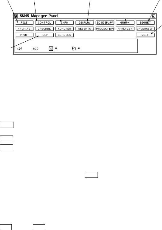
After starting the package a banner will appear which will vanish after you click the left mouse button in the panel. You are then left with the SNNS manager panel.
File |
Training & |
Information |
Network |
Error Graph |
Network |
||
handling |
testing control |
about single units |
Diagram |
|
|
Definition |
|
|
|
or weights |
|
|
|
|
|
|
|
|
|
|
|
|
|
|
|
|
|
|
|
|
|
|
|
|
|
|
|
|
|
Exit
Help
Figure 4.1: The SNNS manager panel
The SNNS manager allows you to access all functions o ered by the package. It is a professional tool and you may nd it a little intimidating. You will not need to use the majority of the options. You should read this introduction while running the simulator - the whole thing is quite intuitive and you will nd your way around it very quickly.
4.1.2Reading and Writing Files
SNNS supports ve types of les, the most important ones are:
NET Network de nition les containing information on network topology and learning rules. The les end in the extension '.net'.
PAT Pattern les, containing the training and test data. All pattern les end in '.pat'.
RES Results les. Network output is interpreted in many possible ways, depending on the problem. SNNS allows the user to dump the network outputs into a separatele for later analysis.
The other two le types are not important for a rst exploration of SNNS.
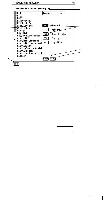
The rst thing you are likely to use is the FILE option in the manager panel to read network and pattern de nition les. The window that will appear is given in gure 4.2.
The top text eld shows the current directory. The main eld shows all les for each of the le types that SNNS can read/write. Directories are marked by square brackets. To load an example network change the directory by entering the example directory path in the top eld (do not press return):
SNNSv4.2/examples
Changes will only be apparent after one of the le selectors has been touched:click on PAT and then NET again. You should now see a list of all network de nition les
4.1. BASIC SNNS USAGE |
31 |
current directory
 file name
file type selectors
list of existing files
scrollbar 
click here to
load save
click here when done
Figure 4.2: The SNNS le browser
currently available. Double-clicking on one of the lenames, say 'letters' will copy the network name into the le name window. To load the network simply click on LOAD . You can also enter the lename directly into the le name window (top left).
4.1.3Creating New Networks
You will need to create your own networks. SNNS allows the creation of many di erent network types. Here is an example of how to create a conventional (fully connected) feed-forward network.
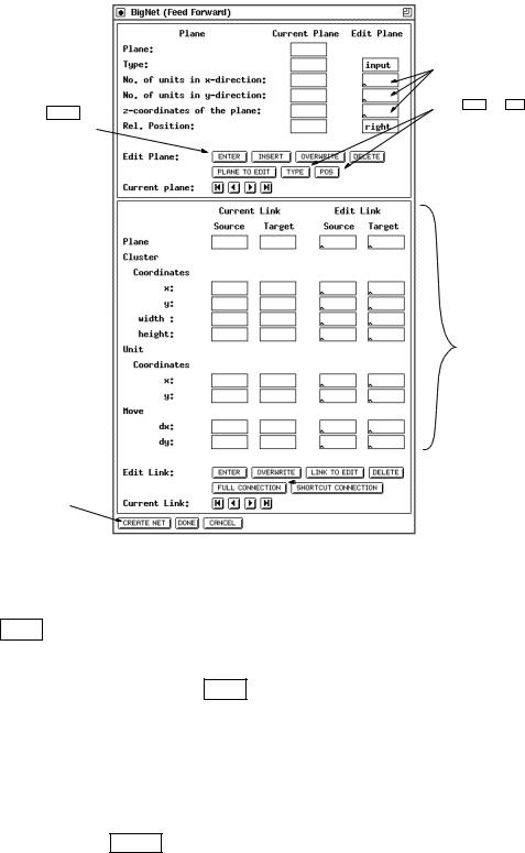
First select the GENERAL option, hidden under the BIGNET button in the manager panel. You are then faced with the panel in gure 4.3. Only two parts of the panel are required.
The top allows the de nition of the network topology, that is how many units are required in each layer and how they should appear if the network is displayed on the screen. The lower part allows you to fully connect the layers and to create the network.
Note that much of what you are de ning here is purely cosmetic. The pattern les contain a given number of inputs and outputs, they have to match the network topology how they are arranged in the display is not important for the functionality.
First you have to de ne the input layer by lling the blanks in the top right hand corner (edit plane) of the panel. The panel shows the current settings for each group of units (a plane in SNNS terminology). Each group is of a given type (i.e. input, hidden or output), and each plane contains a number of units arranged in an x-y-z coordinate system. This is used for drawing networks only!
You can change the entries by entering values into the boxes or by clicking on TYPE and
32 |
CHAPTER 4. USING THE GRAPHICAL USER INTERFACE |
ENTER defines plane
as the last step create network here
enter layer topology here
select TYPE and POS to change unit types and relative position
at the moment ignore all this
 click here to fully connect all layers
Figure 4.3: The SNNS BigNet Feedforward network designer panel
POS to change the unit type and relative position. The relative position is not used for the rst plane of units (there is nothing to position it relatively to). The layers will, for instance, be positioned below the previous layers if the 'Rel. Position' has been changed to 'below' by clicking on the POS button.
Here is an example of how to create a simple pattern associator network with a 5x7 matrix of inputs inputs, 10 hidden units and 26 outputs:
Leave 'Type' as input set no 'x' direction to 5 set no 'y' direction to 7 and click on ENTER
If the input is acceptable it will be copied to the column to the left. The next step is to de ne the hidden layer, containing 10 units, positioned to the right the inputs.
4.1. BASIC SNNS USAGE |
33 |
|||||
|
|
|
|
|
|
|
Change 'Type' from input to hidden by clicking on |
TYPE |
once. |
||||
set no 'x' direction to 1 |
|
|||||
set no 'y' direction to 10 |
|
|||||
change 'Rel.Position' to 'below' by clicking on |
POS |
|
|
|||
and click on |
ENTER |
|
|
|||
You are now ready to de ne the output plane, here you want 26 output units to the right of the input. You may want to save space and arrange the 26 outputs as two columns of 13 units each.
Change 'Type' from hidden to output by clicking on TYPE again. set no 'x' direction to 2
set no 'y' direction to 13 and click on ENTER
After de ning the layer topology the connections have to be made. Simply click on FULL CONNECTION (bottom left of lower panel). Then select CREATE NET and
DONE . You may have to con rm the destruction of any network already present.
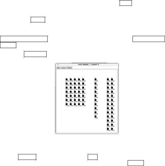
Selection of DISPLAY from the SNNS-manager panel should result in gure 4.4.
Figure 4.4: SNNS network display panel
The lines showing the weights are not normally visible, you have to switch them on by selecting SETUP , and then clicking on the ON button next to 'links' option. You will
nd that SNNS refuses any further input until you have selected DONE .
After creating the network and loading in the pattern le(s) - which have to t the network topology - you can start training the net. The network you have just created should t the \letters" patterns in the SNNS examples directory.
An alternate way to construct a network is via the graphical network editor build into SNNS. It is best suited to alter an existing large network or to create a new small one. For the creation of large networks use bignet. The network editor is described in chapter 6.
34 |
CHAPTER 4. USING THE GRAPHICAL USER INTERFACE |
4.1.4Training Networks
Load the 'letters' pattern le (in the SNNS examples directory) at this stage. The network is a pattern associator that can be trained to map an input image (5x7 pixel representation of letters) into output units where each letter is represented by an output unit.
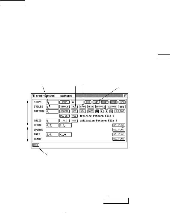
All training and testing is done via the control panel. It is opened by clicking on the CONTROL button of the manager panel. The most important features of this panel will now be discussed one by one. The panel consists of two parts. The top part controls the parameters de ning the training process, the bottom four rows are blanks that have to belled in to de ne the learning rates and the range over which weights will be randomly distributed when the network is initialised, etc. The defaults for the learning parameters are (0.2 0) while the default weight setting is between 1 and -1 (1.0 -1.0).
4.1.4.1Initialization
Many networks have to be initialised before they can be used. To do this, click on INIT (top line of buttons in control). You can change the range of random numbers used in the initialization by entering appropriate values into the elds to the right of \INIT" at the lower end of the control panel.
enter no of cycles here |
start / stop training |
Training
Control
Parameters
Learning
Parameters
click here when done
initialize network
 click here to present patterns in random order
 Select learning function from this button
Figure 4.5: SNNS network training and testing control panel
4.1.4.2Selecting a learning function
The default learning function for feed-forward nets is Std Backpropagation, you may want something a little more extravagant. Simply click on SEL FUNC (Select function next to the learning parameters, see gure 4.5) and pick what you want to use. The routines you may want to consider are Std Backpropagation, BackpropMomentum or Rprop). Use BackpropMomentum for the letters example.
4.1. BASIC SNNS USAGE |
35 |
Each learning function requires a di erent parameter set: here are the important ones, details are given in the manual:
Std Backpropagation 1: learning rate (0-1), 2: dmax , the maximum error that is tolerated. use 0 or a small value.
BackpropMomentum 1: learning rate (0-1), 2: momentum term (0-0.99), 3: c at spot elimination (ignore) and 4: dmax max ignored error.
Rprop 1: starting values of ij (0-0.2) 2: max maximum update value (30 works well..) 3: the weight decay term as an exponent (5 works for most problems) x = 10; = 0:00001.
Once all parameters are set you are ready to do some training. Training is done for a number of 'CYCLES' or epochs (enter a number, say 200 - see g. 4.5). All training patterns are presented once during each cycle. It is sometimes preferable to select the patterns randomly for presentation rather than in order: Click on SHUFFLE to do this.
For the pattern associator example leave the learning rate at 0.2 and set the momentum term (second eld) to 0.5 leave everything else at 0.
Before starting the learning process you may like to open a GRAPH panel (from the manager panel) to monitor the progress during training.1
Click on ALL to start training and STOP to interrupt training at any time. The graph will start on the left whenever the network is initialised so that it is easy to compare di erent learning parameters. The current errors are also displayed on the screen so that they could be used in any graph plotting package (like xmgr).
It is impossible to judge the network performance from the training data alone. It is therefore sensible to load in a 'test' set once in a while to ensure that the net is not over-training and generalising correctly. There is no test set for the letters example. You can have up to 5 di erent data sets active at any one time. The two USE buttons on the control panel allow you to select which data sets to use for training and validation. The top button selects the training set, the bottom one the 'validation set'. If you enter a non-zero value into the box next to VALID a validation data set will be tested and the root-mean-square error will be plotted on the graph in red every N cycles (N is the number you entered in the box).
You can also step through all the patterns in a data set and, without updating any weight, calculate the output activations. To step through the patterns click on TEST .
You can go to any pattern in the training data set by either specifying the pattern number in the eld next to 'PATTERN' and clicking on GOTO or by using the 'tape player
controls' positioned to the right of GOTO . The outputs given by the network when stepping though the data are the targets, not the calculated outputs (!).
1If you do this scale the y-range to lie between 0 and 26 by clicking on the 'right-arrow' next the 'Scale Y:' a few times. You can also resize the window containing the graph.
36 |
CHAPTER 4. USING THE GRAPHICAL USER INTERFACE |
4.1.5Saving Results for Testing
Network performance measures depend on the problem. If the network has to perform a classi cation task it is common to calculate the error as a percentage of correct classi cations. It is possible to tolerate quite high errors in the output activations. If the network has to match a smooth function it may be most sensible to calculate the RMS error over all output units etc.
The most sensible way to progress is to save the output activations together with target values for the test data and to write a little program that does whatever testing is required. The RES les under FILE are just the ticket: Note that the output patterns are always saved. The 'include output patterns' actually means 'include target (!) patterns'.
4.1.6Further Explorations
It is possible to visualize the weights by plotting them, just like the output values as boxes of di erent sizes/colour. Sometimes examining the weights gives helpful insights into how
the networks work. Select WEIGHTS from the manager panel to see the weight diagram.
4.1.7SNNS File Formats
4.1.7.1Pattern les
To train a network on your own data you rst have to massage the data into a format that SNNS can understand. Fortunately this is quite easy. SNNS data les have a header component and a data component. The header de nes how many patterns the le contains as well as the dimensionality of the input and target vectors. The les are saved as ASCII test. An example is given in gure 4.6.
The header has to conform exactly to the SNNS format, so watch out for extra spaces etc. You may copy the header from one of the example pattern les and to edit the numbers, or use the tool mkhead from the tools directory. The data component of the pattern le is simply a listing of numbers that represent the activations of the input and output units. For each pattern the number of values has to match the number of input plus the number of output units of the network as de ned in the header. For clarity you may wish to put comments (lines starting with a hash (#)) between your patterns like shown in gure 4.6. They are ignored by SNNS but may be used by some pattern processing tools. The pattern de nitions may have 'CR' characters (Carriage Return) in them.
Note that while the results saved by SNNS use (almost) the same le format as used for the pattern les, the label values de ned in the pattern les are not used.
4.1.7.2Network les
The networks les, just as the pattern and result les are stored as ASCII les, they are relatively easy to read and you may nd it easier to hand-edit the network de nition le

4.2. XGUI FILES |
37 |
SNNS pattern definition file V3.2 generated at Wed Aug 9 11:01:29 1995
No. of patterns : 4772
No. of input units : 16
No. of output units : 1
# 2
0 2 2 0 -1 -1 0.91 0.91 0 1 0 0 0.01 0.01 0.34 -0.09 0.0
#4
12 2 1 -1 4 2.93 2.93 0 0.95 0 0 0 0 0 0.75 1.0
#10
02 2 0 1 2 3.43 2.15 0 0.94 0 0 0 0 0 0.65 1.0
#12
00 2 0 1 -1 2.89 2.89 0 0.95 0 0 0 0 0 0.78 0.0
#14
02 0 0 -1 -1 2.59 ...
Figure 4.6: Pattern le diagram
File header
data
every new pattern starts with #label
could also use
#input 0 1 0 0 1
#target
1 etc
than to use the graphical user interface to perform tasks such as changing the unit transfer function or to change the network topology.
4.2XGUI Files
The graphical user interface consists of the following les:
xgui |
SNNS simulator program (XGUI and simulator kernel |
|
linked together into one executable program) |
default.cfg |
default con guration (see chapter 4.3.2) |
help.hdoc |
help text used by XGUI |
The le Readme xgui contains changes performed after printing of this document. The user is urged to read it, prior to using XGUI. The le help.hdoc is explained in chapter 4.3.11.
XGUI looks for the les default.cfg and help.hdoc rst in the current directory. If not found there, it looks in the directory speci ed by the environment variable XGUILOADPATH. By the command
setenv XGUILOADPATH Path
this variable can be set to the path where default.cfg and help.hdoc are located. This is best done by an entry to the les .login or .cshrc. Advanced users may change the help le or the default con guration for their own purposes. This should be done, however, only on a copy of the les in a private directory.
SNNS uses the following extensions for its les:
38 |
CHAPTER 4. USING THE GRAPHICAL USER INTERFACE |
.net network les (units and link weights)
.pat pattern les
.cfg con guration settings les
.txt text les (log les)
.res result les (unit activations)
A simulator run is started by the command
xgui [<netfile>.net] [<pattern>.pat] [<config>.cfg] [options] Return where valid options are
-font <name> : font for the simulator -dfont <name> : font for the displays -mono : black & white on color screens -help : help screen to explain the options
in the installation directory of SNNS or by directly calling
<SNNS-directory>/xgui/bin/<architecture>/xgui
from any directory. Note that the shell variable XGUILOADPATH must be set properly before, or SNNS will complain about missing les default.cfg and help.hdoc.
The executable xgui may also be called with X-Window parameters as arguments.
Setting the display font can be advisable, if the font selected by the SNNS automatic font detection looks ugly. The following example starts the display with the 7x13bold font
snns -font 7x13bold Return
The fonts which are available can be detected with the program xfontsel (not part of this distribution).
4.3Windows of XGUI
The graphical user interface has the following windows, which can be positioned and handled independently (toplevel shells):
Manager panel with buttons to open other windows, a message line, and a line with status information at the bottom .
File browser for loading and saving networks and pattern les.
Control panel for simulator operations.
Info panel for setting and getting information about unit and link attributes.
several Displays, to display the network graphically in two dimensions.
3D View panel to control the three dimensional network visualization component.