

Параллельные Процессы и Параллельное Программирование / SNNSv4.2.Manual
.pdf11.2. USE OF THE 3D-INTERFACE |
229 |
Figure 11.8: Control Panel
SETUP : basic settings like rotation angles are selected
MODEL : switch between solid model and wireframe model
PROJECT : selects parallel or central projection
LIGHT : chooses lighting parameter
UNITS : selects various unit display options
LINKS : selects link display options
RESET : resets all 3D settings to their original values
FREEZE : freezes the 3D-display
3.the panel with the buttons
DISPLAY : opens the 3D-display (max. one)
DONE : closes the 3D-display window and the 3D-control window and exits the 3D visualization component
4.the z-value panel: used for input of z-values either directly or incrementally with the arrow buttons
11.2.4.1Transformation Panels
With the transformation panels, the position and size of the network can be controlled.
In the rotate panel, the net is rotated around the x-, y-, or z-axis. The + buttons rotate clockwise, the - buttons counterclockwise. The center elds X, Y and Z are no buttons but framed in similar way for pleasant viewing.
In the trans panel, the net is moved along the x-, y-, or z-axis. The + buttons move to the right, the - buttons to the left. The center elds X, Y and Z are no buttons but framed in similar way for pleasant viewing.
In the scale panel, the net can be shrunk or enlarged.
230 |
CHAPTER 11. 3D-VISUALIZATION OF NEURAL NETWORKS |
11.2.4.2Setup Panel
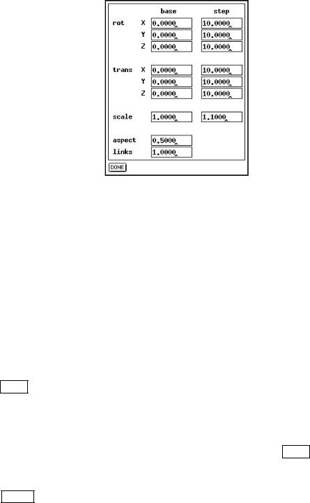
Figure 11.9: Setup Panel
In the base column of the setup panel, the transformation parameters can be set explicitly to certain values. The rotation angle is given in degrees as a nine digit oat number, the transposition is given in pixels, the scale factor relative to 1. Upon opening the window, the elds contain the values set by the transformation panels, or the values read from the con guration le. The default value for all elds is zero. The net is then displayed just as in the 2D-display.
In the step column the step size for the transformations can be set. The default for rotation is ten degrees, the default for moving is 10 pixel. The scaling factor is set to 1.1.
In the aspect eld the ratio between edge length of the units and distance between units is set. Default is edge length equals distance.
With links the scale factor for drawing links can be set. It is set to 1.0 by default.
The DONE button closes the panel and redraws the net.
11.2.4.3Model Panel
In the model panel the representation of the units is set. With the WIRE button a wire frame model representation is selected. The units then consist only of edges and appear transparent.
The SOLID button creates a solid representation of the net. Here all hidden lines are eliminated. The units' surfaces are shaded according to the illumination parameters if no other value determines the color of the units.
When the net is to be changed, the user is advised to use the wire frame model until the desired con guration is reached. This speeds up the display by an order of magnitude.
11.2. USE OF THE 3D-INTERFACE |
231 |
11.2.4.4Project Panel
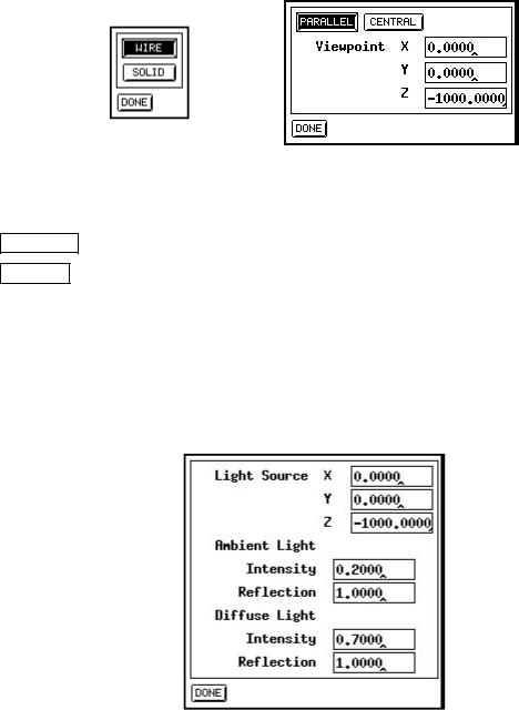
Figure 11.10: Model Panel (left) and Project Panel (right)
Here the kind of projection is selected.
PARALLEL selects parallel projection, i.e. parallels in the original space remain parallel.
CENTRAL selects central projection, i.e. parallels in original original space intersect in the
display.
With the Viewpoint elds, the position of the viewer can be set. Default is the point (0, 0, -1000) which is on the negative z-axis. When the viewer approaches the origin the network appears more distorted.
11.2.4.5Light Panel
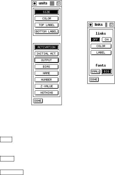
Figure 11.11: Light Panel
In the light panel, position and parameters of the light source can be set. The elds Position determine the location of the source. It is set to (0, 0, -1000) by default, which is the point of the viewer. This means that the net is illuminated exactly from the front. A point in positive z-range is not advisable, since all surfaces would then be shaded.
With the Ambient Light elds, the parameters for the background light are set.
232 |
CHAPTER 11. 3D-VISUALIZATION OF NEURAL NETWORKS |
Intensity sets the intensity of the background brightness.
Reflection is the re ection constant for the background re ection. (0 Ref. 1) The elds Diffuse Light determine the parameters for di use re ection.
Intensity sets the intensity of the light source.
Reflection is the re ection constant for di use re ection. (0 Ref. 1)
11.2.4.6Unit Panel
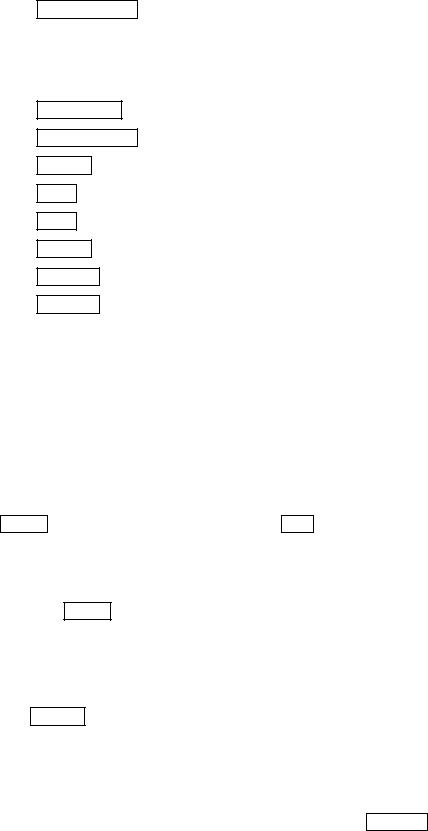
Figure 11.12: Unit Panel (left) and Link Panel (right)
With the unit panel the representation of the units can be set. The upper part shows the various properties that can be used to display the values:
SIZE : a value is represented by the size of the unit. The maximum size is de ned by the Aspect eld in the setup panel. Negative and small positive values are not displayed.
COLOR : a value is represented by the color of the unit. A positive value is displayed green, a negative red. This option is available only on color terminals.
TOP LABEL : a value is described by a string in the upper right corner of the unit.
11.2. USE OF THE 3D-INTERFACE |
233 |
unit.BOTTOM LABEL : a value is described by a string in the lower right corner of the
In the lower part the type of the displayed value, selected by a button in the upper part, can be set. It is displayed by
ACTIVATION : the current activation of the unit.
INITIAL ACT. : the initial activation of the unit.
OUTPUT : the output value of the unit.
BIAS : the threshold of the unit.
NAME : the name of the unit.
NUMBER : the number of the unit.
Z-VALUE : the z-coordinate of the unit.
NOTHING : no value.
The options NAME, NUMBER and Z-value can be used only with the top or bottom label. The other values can be combined freely, so that four values can be displayed simultaneously.
11.2.4.7Links Panel
In the links panel the representation of the links can be switched on and o with the
buttons |
ON |
and |
OFF |
. The button |
|
COLOR |
|
forces color representation of the links (only |
with color monitors), and the button |
|
LABEL |
|
writes the weights of the links in the middle. |
||||
In the fonts part of the panel, the fonts for labeling the links can be selected. The button SMALL activates the 5 8 font, the button BIG the 8 14 font
11.2.4.8Reset Button
With the RESET button the values for moving and rotating are set to zero. The scaling factor is set to one.
11.2.4.9Freeze Button
The FREEZE button keeps the network from being redrawn.
11.2.53D-Display Window
In the display window the network is shown (see gure 11.7). It has no buttons, since it is fully controlled by the control panel. It is opened by the DISPLAY button of the control panel. When the control panel is closed, the display window is closed as well.
234 |
CHAPTER 11. 3D-VISUALIZATION OF NEURAL NETWORKS |
Note: The 3D-display is only a display window, while the 2D-display windows have a graphical editor integrated. There is also no possibility to print the 3D-display via the print panel.
Chapter 12
Batchman
Since training a neural network may require several hours of CPU time, it is advisable to perform this task as a batch job during low usage times. SNNS o ers the program batchman for this purpose. It is basically an additional interface to the kernel that allows easy background execution.
12.1Introduction
This newly implemented batch language is to replace the old snnsbat. Programs which are written in the old snnsbat language will not be able to run on the newly designed interpreter. Snnsbat is not supported any longer, but we keep the program for those users who are comfortable with it and do not want to switch to batchman. The new language supports all functions which are necessary to train and test neural nets. All non-graphical features which are o ered by the graphical user interface (XGUI) may be accessed with the help of this language as well.
The new batch language was modeled after languages like AWK, Pascal, Modula2 and C. It is an advantage to have some knowledge in one of the described languages. The language will enable the user to get the desired result without investing a lot of time in learning its syntactical structure. For most operators multiple spellings are possible and variables don't have to be declared before they are used. If an error occurs in the written batch program the user will be informed by a displayed meaningful error message (warning) and the corresponding line number.
12.1.1Styling Conventions
Here is a description of the style conventions used:
Input which occurs on a Unix command line or which is part of the batch program will be displayed in typewriter writing. Such an input should be adopted without any mod- i cation.
236 |
CHAPTER 12. BATCHMAN |
For example:
/Unix> batchman -h
This is an instruction which should be entered in the Unix command line, where /Unix> is the shell prompt which expects input from the user. Its appearance may change depending on the Unix-system installed. The instruction batchman -h starts the interpreter with the -h help option which tells the interpreter to display a help message. Every form of input has to be con rmed with Enter (Return). Batch programs or part of batch programs will also be displayed in typewriter writing. Batch programs can be written with a conventional text editor and saved in a le. Commands can also be entered in the interactive mode of the interpreter. If a le is used as a source to enter instructions, the name of the le has to be provided when starting the interpreter. Typewriter writing is also used for wild cards. Those wild cards have to be replaced by real names.
12.1.2Calling the Batch Interpreter
The Interpreter can be used in an interactive mode or with the help of a le, containing the batch program. When using a le no input from the keyboard is necessary. The interactive mode can be activated by just calling the interpreter:
/Unix> batchman
which produces:
SNNS Batch Interpreter V1.0. Type batchman -h for help. No input file specified, reading input from stdin. batchman>
Now the interpreter is ready to accept the user's instructions, which can be entered with the help of the keyboard. Once the input is completed the interpreter can be put to work with Ctrl-D. The interpreter can be aborted with Ctrl-C. The instructions entered are only invoked after Ctrl-D is pressed.
If the user decides to use a le for input the command line option -f has to be given together with the name of the interpreter:
/Unix> batchman -f myprog.bat
Once this is completed, the interpreter starts the program contained in the le myprog.bat and executes its commands.
The standard output is usually the screen but with the command line option -l the output can be redirected in a protocol le. The name of the le has to follow the command line option:
/Unix> batchman -l logfile
Usually the output is redirected in combination with the reading of the program out of ale:
12.2. DESCRIPTION OF THE BATCH LANGUAGE |
237 |
/Unix> batchman -f myprog.bat -l logfile
The order of the command line options is arbitrary. Note, that all output lines of batchman that are generated automatically (e.g. Information about with pattern le is loaded or saved) are preceded by the hash sign \#". This way any produced log le can be processed directly by all programms that treat \#" as a comment delimiter, e.g. gnuplot.
The other command line options are:
-p: Programs should only be parsed but not executed. This option tells the interpreter to check the correctness of the program without executing the instructions contained in the program. Run time errors can not be detected. Such a run time error could be an invalid SNNS function call.
-q: No messages should be displayed except those caused by the print()- function.
-s: No warnings should be displayed.
-h: A help message should be displayed which describes the available command line options.
All following input will be printed without the shell-text.
12.2Description of the Batch Language
This section explains the general structure of a batch program, the usage of variables of the di erent data types and usage of the print function. After this an introduction to control structures follows.
12.2.1Structure of a Batch Program
The structure of a batch program is not predetermined. There is no declaration section for variables in the program. All instructions are speci ed in the program according to their execution order. Multiple blanks are allowed between instructions. Even no blanks between instructions are possible if the semantics are clear. Single instructions in a line don't have to be completed by a semicolon. In such a case the end of line character (Ctrl-D) is separating two di erent instructions in two lines. Also key words which have the responsibility of determining the end of a block (endwhile, endif, endfor, until and else) don't have to be completed by a semicolon. Multiple semicolons are possible between two instructions. However if there are more than two instructions in a line the semicolon is necessary. Comments in the source code of the programs start with a '#' character. Then the rest of the line will be regarded as a comment.
A comment could have the following appearance:
#This is a comment
a:=4 #This is another comment

238 |
CHAPTER 12. BATCHMAN |
The second line begins with an instruction and ends with a comment.
12.2.2Data Types and Variables
The batch language is able to recognize the following data types:
Integer numbers
Floating point numbers
Boolean type 'TRUE' and 'FALSE'
Strings
The creation of oat numbers is similar to a creation of such numbers in the language C because they both use the exponential representation. Float numbers would be: 0.42,
3e3, or 0.7E-12. The value of 0.7E-12 would be 0:7 10;12 and the value of 3e3 would be 3 103
Boolean values are entered as shown above and without any kind of modi cation.
Strings have to be enclosed by " and can not contain the tabulator character. Strings also have to contain at least one character and can not be longer than one line. Such strings could be:
"This is a string"
"This is also a string (0.7E-12)"
The following example would yield an error
"But this
is not a string"
12.2.3Variables
In order to save values it is possible to use variables in the batch language. A variable is introduced to the interpreter automatically once it is used for the rst time. No previous declaration is required. Names of variables must start with a letter or an underscore. Digits, letters or more underscores could follow. Names could be:
a, num1, test, first net, k17 u, Test buffer 1
The interpreter distinguishes between lower and upper case letters. The type of a variable is not known until a value is assigned to it. The variable has the same type as the assigned value:
a = 5
filename := "first.net" init flag := TRUE