

Параллельные Процессы и Параллельное Программирование / SNNSv4.2.Manual
.pdfChapter 7
Graphical Network Creation Tools
SNNS provides ten tools for easy creation of large, regular networks. All these tools carry the common name BigNet. They are called by clicking the button BIGNET in the manager panel. This invokes the selection menu given below, where the individual tools can be selected. This chapter gives a short indroduction to the handling of each of them.
general
time delay
art 1
art 2
artmap
kohonen
jordan
elman
hopfield
auto assoz
Note, that there are other network creation tools to be called from the Unix command line. Those tools are described in chapter 13.
7.1BigNet for Feed-Forward and Recurrent Networks
7.1.1Terminology of the Tool BigNet
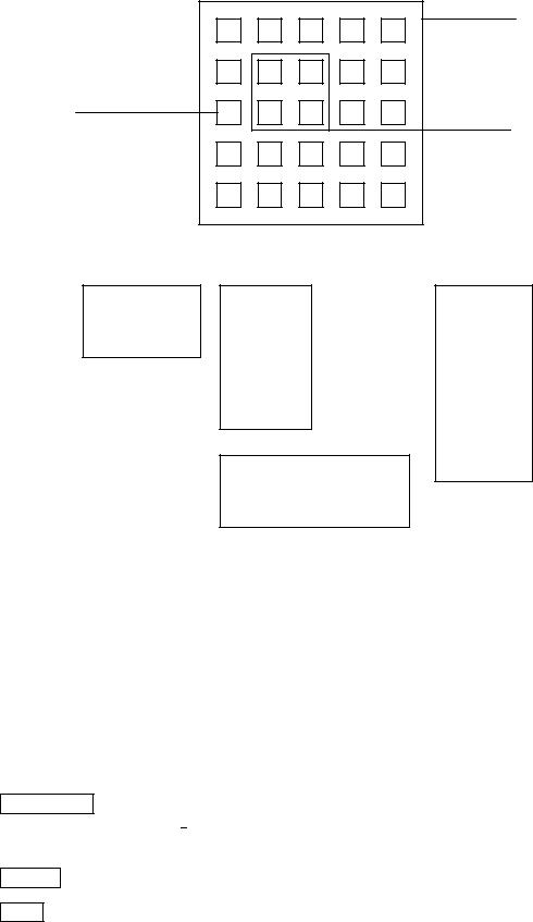
BigNet subdivides a net into several planes. The input layer, the output layer and every hidden layer are called a plane in the notation of BigNet. A plane is a two-dimensional array of units. Every single unit within a plane can be addressed by its coordinates. The unit in the upper left corner of every plane has the coordinates (1,1). A group of units within a plane, ordered in the shape of a square, is called a cluster. The position of a cluster is determined by the coordinates of its upper left corner and its expansion in the x direction (width) and y direction (height) ( g. 7.2).
120 |
CHAPTER 7. GRAPHICAL NETWORK CREATION TOOLS |
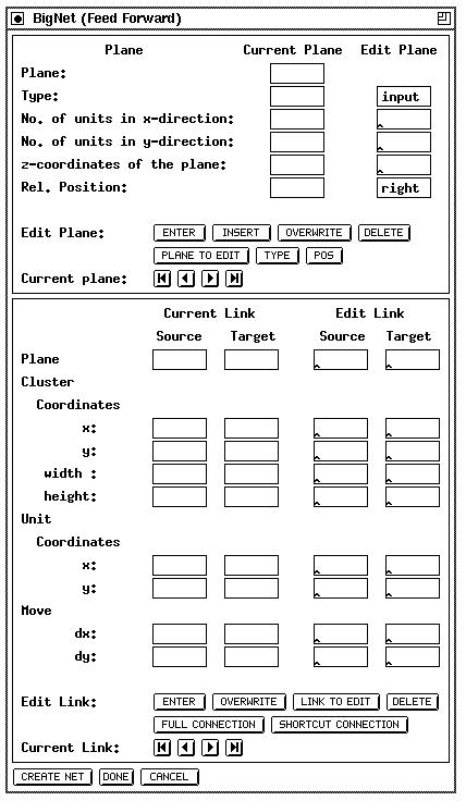
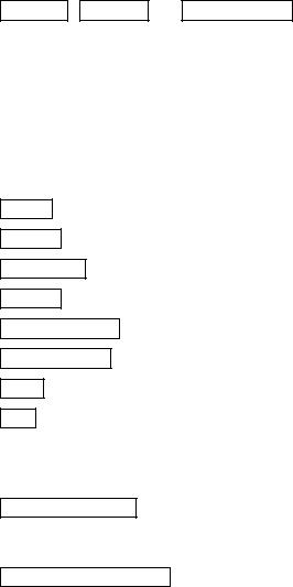
Figure 7.1: The BigNet window for Feed-Forward and recurrent Networks
7.1. BIGNET FOR FEED-FORWARD AND RECURRENT NETWORKS |
121 |
BigNet creates a net in two steps:
1.Edit net: This generates internal data structures in BigNet which describe the network but doesn't generate the network yet. This allows for easy modi cation of the network parameters before creation of the net.
The net editor consists of two parts:
(a)The plane editing part for editing planes. The input data is stored in the plane list.
(b)The link editing part for editing links between planes. The input data is stored in the link list.
2.Generate net in SNNS: This generates the network from the internal data structures in BigNet.
Both editor parts are subdivided into an input part (Edit plane, Edit link) and into a display part for control purposes (Current plane, Current link). The input data of both editors is stored, as described above, in the plane list and in the link list. After pressing ENTER , INSERT , or OVERWRITE the input data is added to the corresponding
editor list. In the control part one list element is always visible. The buttons  ,
,  ,
,  , and
, and  enable moving around in the list. The operations DELETE, INSERT, OVERWRITE, CURRENT PLANE TO EDITOR and CURRENT LINK TO EDITOR refer to the current element. Input data is only entered in the editor list if it is correct, otherwise nothing happens.
7.1.2Buttons of BigNet
ENTER : Input data is entered at the end of the plane or the link list.
INSERT : Input data is inserted in the plane list in front of the current plane.
OVERWRITE : The current element is replaced by the input data.
DELETE : The current element is deleted.
PLANE TO EDIT : The data of the current plane is written to the edit plane.
LINK TO EDIT : The data of the current link is written to the edit link.
TYPE : The type (input, hidden, output) of the units of a plane is determined.
POS : The position of a plane is always described relative (left, right, below) to the position of the previous plane. The upper left corner of the rst plane is positioned at the coordinates (1,1) as described in Figure 7.3. BigNet then automatically generates the coordinates of the units.
FULL CONNECTION : A fully connected feed forward net is generated. If there are n planes numbered 1::n then every unit in plane i with i > 0 is connected with every unit in plane i + 1 for all 1 i n ; 1.
SHORTCUT CONNECTION : If there exist n planes 1 : : : n then every unit in plane i with 1 i < n is connected with every unit in all planes j with i < j n.
122
Unit :
x : 1
y : 3
CHAPTER 7. GRAPHICAL NETWORK CREATION TOOLS
Plane : x : 5 y : 5
Cluster : |
|
|
x |
: |
2 |
y |
: |
2 |
width |
: |
2 |
height : |
2 |
|
Figure 7.2: Clusters and units in BigNet
Plane 1 |
Plane 2 |
Plane 4 |
|
|
right
right
Plane 3
below
Plane 5 |
|
|
Plane 6 |
|
|
|
|
|
left |
|
|
|
|
|
right |
|
|
|
|
Figure 7.3: Positioning of the planes
CREATE NET : The net described by the two editors is generated by SNNS. The default name of the net is SNNS NET.net. If a net with this name already exists a warning is issued before it is replaced.
CANCEL : All internal data of the editors is deleted.
DONE : Exit BigNet and return to the simulator windows.
7.1. BIGNET FOR FEED-FORWARD AND RECURRENT NETWORKS |
123 |
7.1.3Plane Editor
Every plane is characterized by the number of units in x and y direction. The unit type of a plane can be de ned and changed by TYPE . The position of the planes is determined relative to the previous plane. The upper left corner of plane no. 1 is always positioned at the coordinates (1 1). Pressing POS , one can choose between `left', `right' and `below'. Figure 7.3 shows the layout of a network with 6 planes which were positioned relative to their predecessors as indicated starting with plane 1.
Every plane is associated with a plane number. This number is introduced to address the planes in a clear way. The number is important for the link editor. The user cannot change this number.
In the current implementation the z coordinate is not used by BIGNET. It has been implemented for future use with the 3D visualization component.
7.1.4Link Editor
A link always leads from a source to a target. To generate a fully connected net (connections from each layer to its succeeding layer, no shortcut connections), it is only su cient to press the button FULL CONNECTION after the planes of the net are de ned. Scrolling through the link list, one can see that every plane i is connected with the plane i + 1. The plane number shown in the link editor is the same as the plane number given by the plane editor.
If one wants more complicated links between the planes one can edit them directly. There are nine di erent combinations to specify link connectivity patterns:
> |
all units of a plane |
> |
> |
all units of a plane |
> |
|
|
|
|
|
|
||||
Links from8 all units of a cluster 9to 8 all units of a cluster 9 |
: |
||||||
< |
|
a single unit |
= |
< |
a single unit |
= |
|
> |
|
|
> |
> |
|
> |
|
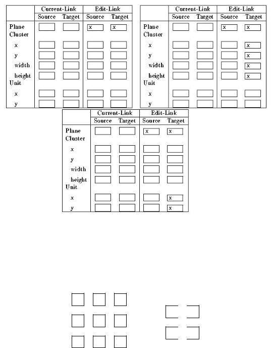
Figure 7.4 shows: |
the display for the three: possible input combinations with (all units of) |
||||||
a plane as source. The other combinations are similar. Note that both source plane and target plane must be speci ed in all cases, even if source or target consists of a cluster of units or a single unit. If the input data is inconsistent with the above rules it is rejected with a warning and not entered into the link list after pressing ENTER or OVERWRITE .
With the Move parameters one can declare how many steps a cluster or a unit will be moved in x or y direction within a plane after the cluster or the unit is connected with a target or a source. This facilitates the construction of receptive elds where all units of a cluster feed into a single target unit and this connectivity pattern is repeated in both directions with a displacement of one unit.
The parameter dx (delta-x) de nes the step width in the x direction and dy (delta-y) de nes the step width in the y direction. If there is no entry in dx or dy there is no movement in this direction. Movements within the source plane and the target plane is independent from each other. Since this feature is very powerful and versatile it will be illustrated with some examples.
124 |
CHAPTER 7. GRAPHICAL NETWORK CREATION TOOLS |
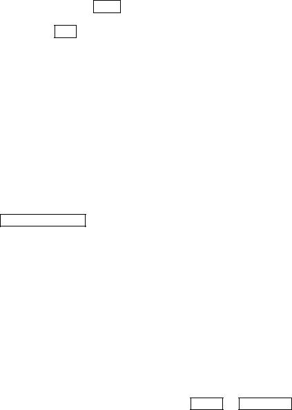
Figure 7.4: possible input combinations with (all units of) a plane as source, between 1) a plane and a plane, 2) a plane and a cluster, 3) a plane and a unit. Note that the target plane is speci ed in all three cases since it is necessary to indicate the target cluster or target unit.
Example 1: Receptive Fields in Two Dimensions
1,1 1,2 1,3
1,1
 1,2
1,2
2,1 2,2 2,3
2,1
 2,2
2,2
3,1 3,2 3,3
Figure 7.5: The net of example 1
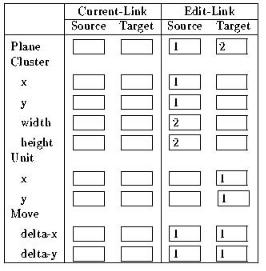
There are two planes given ( g. 7.5). To realize the links
source: plane 1 (1,1), (1,2), (2,1) (2,2) ;! target: plane 2 (1,1) source: plane 1 (1,2), (1,3), (2,2) (2,3) ;! target: plane 2 (1,2) source: plane 1 (2,1), (2,2), (3,1) (3,2) ;! target: plane 2 (2,1) source: plane 1 (2,2), (2,3), (3,2) (3,3) ;! target: plane 2 (2,2)
7.1. BIGNET FOR FEED-FORWARD AND RECURRENT NETWORKS |
125 |
between the two planes, the move data shown in gure 7.6 must be inserted in the link editor.
Figure 7.6: Example 1
First, the cluster (1,1), (1,2), (2,1) (2,2) is connected with the unit (1,1). After this step the source cluster and the target unit are moved right one step (this corresponds to dx = 1 for the source plane and the target plane). The new cluster is now connected with the new unit. The movement and connection building is repeated until either the source cluster or the target unit has reached the greatest possible x value. Then the internal unit pointer moves moves down one unit (this corresponds to dy = 1 for both planes) and back to the beginning of the planes. The \moving" continues in both directions until the boundaries of the two planes are reached.
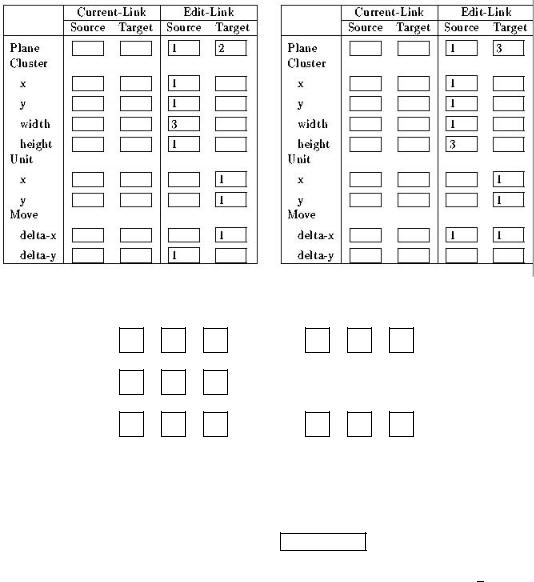
Example 2: Moving in Di erent Dimensions
This time the net consists of three planes ( g. 7.8). To create the links
source: plane1 (1,1), (1,2), (1,3) ;! target: plane 2 (1,1) source: plane1 (2,1), (2,2), (2,3) ;! target: plane 2 (1,2) source: plane1 (3,1), (3,2), (3,3) ;! target: plane 2 (1,3) source: plane1 (1,1), (2,1), (3,1) ;! target: plane 3 (1,1) source: plane1 (1,2), (2,2), (3,2) ;! target: plane 3 (1,2) source: plane1 (1,3), (2,3), (3,3) ;! target: plane 3 (1,3)
between the units one must insert the move data shown in gure 7.7. Every line of plane 1 is a cluster of width 3 and height 1 and is connected with a unit of plane 2, and every column of plane 1 is a cluster of width 1 and height 3 and is connected with a unit of plane 3. In this special case one can ll the empty input elds of \move" with any data because a movement in this directions is not possible and therefore these data is neglected.
126 |
CHAPTER 7. GRAPHICAL NETWORK CREATION TOOLS |
Figure 7.7: Example 2
1,1 |
1,2 |
1,3 |
1,1 |
1,2 |
1,3 |
2,1 |
2,2 |
2,3 |
|
|
|
3,1 |
3,2 |
3,3 |
1,1 |
1,2 |
1,3 |
Figure 7.8: The net of example 2
7.1.5Create Net
After one has described the net one must press CREATE NET to generate the net in SNNS. The weights of the links are set to the default value 0:5. Therefore one must initialize the net before one starts learning. The net created has the default name SNNS NET.net. If a net already exists in SNNS a warning is issued before it is replaced. If the network generated happens to have two units with more than one connection in the same direction between them then SNNS sends the error message \Invalid Target".
7.2. BIGNET FOR TIME-DELAY NETWORKS |
127 |
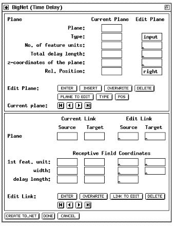
7.2BigNet for Time-Delay Networks
The BigNet window for Time Delay networks ( gure 7.9) consists of three parts: The Plane editor where the number, placement, and type of the units are de ned, the link editor, where the connectivity between the layer is de ned, and three control buttons at the bottom, to create the network, cancel editing, and close the window.
Figure 7.9: The BigNet window for Time Delay Networks
Since the buttons of this window carry mostly the same functionality as in the feed-forward case, refer to the previous section for a description of their use.
7.2.1Terminology of Time-Delay BigNet
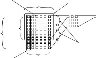
The following naming conventions have been adopted for the BigNet window. Their meaning may be clari ed by gure 7.10.
Receptive Field: The cluster of units in a layer totally connected to one row of units in the next layer.
1st feature unit: The starting row of the receptive eld.
128 |
CHAPTER 7. GRAPHICAL NETWORK CREATION TOOLS |
width: The width of the receptive eld.
delay length: The number of signi cant delay steps of the receptive eld. Must be the same value for all receptive elds in this layer.
No. of feature units: The width of the current layer
Total delay length: The length of the current layer. Total delay length times the number of feature units equals the number of units in this layer. Note that the total delay length must be the same as the delay length plus the total delay length of the next layer minus one!
z-coordinates of the plane: gives the placing of the plane in space. This value may be omitted (default = 0).
3rd Feature Unit
Receptive Field
width
Delay
Total Delay Length
Length
Couppled Weights
"One" Feature Unit |
Number of Feature Units |
Figure 7.10: The naming conventions
7.2.2Plane Editor
Just as in BigNet for feed-forward networks, the net is divided into several planes. The input layer, the output layer and every hidden layer are called a plane in the notation of BigNet. A plane is a two-dimensional array of units. Every single unit within a plane can be addressed by its coordinates. The unit in the upper left corner of every plane has the coordinates (1,1).
See 7.1.3 for a detailed description.
7.2.3Link Editor
In the link panel the connections special to TDNNs can be de ned. In TDNNs links always lead from the receptive eld in a source plane to one or more units of a target plane. Note, that a receptive eld has to be speci ed only once for each plane and is automatically applied to all possible delay steps in that plane. gure 7.11 gives an example of a receptive eld speci cation and the network created thereby.