

Параллельные Процессы и Параллельное Программирование / SNNSv4.2.Manual
.pdf6.4. SHORT COMMAND REFERENCE |
109 |
Units Copy Structure ...: copies all selected units and the link structure between these units, i.e. a whole subnet is copied
Units Copy Structure All: copies all selected units, all links between them, and all input and output links to and from these units
Units Copy Structure Input: copies all selected units, all links between them, and all input links to these units
Units Copy Structure Output: copies all selected units, all links between them, and all output links from these units
Unitsthem Copy Structure None: copies all selected units and all links between
Units Copy Structure Back binding: copies all selected units and all links between them and inserts additional links from the new to the corresponding original units (Sites!)
Units Copy Structure Forward binding: copies all selected units and all links between them and inserts additional links from the original to the corresponding new units (Sites!)
Units Copy Structure Double binding: ditto, but inserts additional links from the original to the new units and vice versa (Sites!)
4.Mode Commands:
Mode Units: unit mode, shortens command sequence if one wants to work with unit commands only. All subsequences after the Units command are valid then
Mode Links: analogous to Mode Units, but for link commands
5.Graphics Commands:
Graphics All: redraws the local window
Graphics Complete: redraws all windows
Graphics Direction: draws all links from and to a unit with arrows in the local window
Graphics Links: redraws all links in the local window
Graphics Move: moves the origin of the local window such that the Target unit is displayed at the position of the mouse pointer
Graphicscated Origin: moves the origin of the local window to the position indi-
Graphicswindow Grid: displays a graphic grid at the raster positions in the localGraphics Units: redraws all units in the local window
110 |
CHAPTER 6. GRAPHICAL NETWORK EDITOR |
6.5Editor Commands
We now describe the editor commands in more detail. The description has the following form that is shown in two examples:
Links Make Clique (selection LINK : site-popup)
First comes the command sequence (Links Make Clique) which is invoked by pressing the keys L, M, and C in this order. The items in parentheses indicate that the command depends on the objects of a previous selection of a group of units with the mouse (selection), that it depends on the value of the LINK eld in the info panel, and that a site-popup appears if there are sites de ned in the network. The options are given in their temporal order, the colon ':' stands for the moment when the last character of the command sequence is pressed, i.e. the selection and the input of the value must precede the last key of the command sequence.
Units Set Activation (selection TARGET :)
The command sequence Units Set Activation is invoked by pressing the keys U, S, A, in that order. The items in parentheses indicate that the command depends on the selection of a group of units with the mouse (selection) which it depends on the value of the TARGET eld and that these two things must be done before the last key of the command sequence is pressed.
The following table displays the meaning of the symbols in parenthesis:
selection |
all selected units |
: |
now the last key of a command sequence is pressed |
[unit] |
the raster cursor is placed on a unit |
[empty] |
the raster cursor is placed on an empty position |
default |
the default values are used |
TARGET |
the TARGET unit eld in the info panel must be set |
LINK |
the LINK eld in the info panel must be set |
site-links |
only links to the current site in the info panel play a role |
site |
the current site in the info panel must be set |
popup |
a popup menu appears to ask for a value |
site-popup |
if there are sites de ned in the network, a popup |
|
appears to choose the site for the operation |
dest? |
a raster position for a destination must be clicked |
|
with the mouse (e.g. in Units Move) |
|
|
In the case of a site-popup a site for the operation can be chosen from this popup window. However, if one clicks the DONE button immediately afterwards, only the direct input without sites is chosen. In the following description, this direct input should be regarded as a special case of a site.
All newly generated units are assigned to all active layers in the display in which the command for their creation was issued.
The following keys are always possible within a command sequence:
6.5. EDITOR COMMANDS |
111 |
Quit: quit a command
Return: quit and return to normal mode
Help: get help information to the commands
A detailed description of the commands follows:
1.Flags Safety (:)
If the SAFETY-Flag is set, then with every operation which deletes units, sites or links (Units Delete ... or Links Delete ...) a con rmer asks if the units, sites or links should really be deleted. If the ag is set, this is shown in the manager panel with a safe after the little ag icon. If the ag is not set, units, sites or links are deleted immediately. There is no undo operation for these deletions.
2.Links Set (selection LINK :)
All link weights between the selected units are set to the value of the LINK eld in the info panel.
3.Links Make Clique (selection LINK : site-popup)
A full connection between all selected units is generated. Since links may be deleted selectively afterwards, this function is useful in many cases where many links in both directions are to be generated.
If a site is selected, a complete connection is only possible if all units have a site with the same name.
4.Links Make from Source unit (selection [unit] : site-popup) Links Make to Target unit (selection [unit] : site-popup)
Both operations connect all selected units with a single unit under the mouse pointer. In the rst case, this unit is the source, in the second, it is the target. All links get the value of the LINK eld in the info panel.
If sites are used, only links to the selected site are generated.
5.Links Make Double (selection :)
All unidirectional links become double (bidirectional) links. That is, new links in the opposite direction are generated. Immediately after creation the new links possess the same weights as the original links. However, the two links do not share the weight, i.e. subsequent training usually changes the similarity.
Connections impinging on a site only become bidirectional, if the original source units has a site with the same name.
6.Links Make Inverse (selection :)
All unidirectional links between all selected units change their direction. They keep their original value.
112 |
CHAPTER 6. GRAPHICAL NETWORK EDITOR |
Connections leading to a site are only reversed, if the original source unit has a site of the same name. Otherwise they remain as they are.
7.Links Delete Clique (selection : site-popup)
Links Delete from Source unit (selection [unit] : site-popup) Links Delete to Target unit (selection [unit] : site-popup)
These three operations are the reverse of Links Make in that they delete the connections. If the safety ag is set (the word safe appears behind the ag symbol in the manager panel), a con rmer window forces the user to con rm the deletion.
8.Links Copy Input (selection [unit] :) Links Copy Output (selection [unit] :) Links Copy All (selection [unit] :)
Links Copy Input copies all input links of the selected group of units to the single unit under the mouse pointer. If sites are used, incoming links are only copied if a site with the same name as in the original units exists.
Links Copy Output copies all output links of the selected group of units to the single unit under the mouse pointer.
Links Copy All Does both of the two operations above
9.Links Copy Environment (selection TARGET site-links [unit] :)
This is a rather complex operation: Links Copy Environment tries to duplicate the links between all selected units and the current TARGET unit in the info panel at the place of the unit under the mouse pointer. The relative position of the selected units to the TARGET unit plays an important role: if a unit exists that has the same relative position to the unit under the mouse cursor as the TARGET unit has to one of the selected units, then a link between this unit and the unit under the mouse pointer is created.
The result of this operation is a copy of the structure of links between the selected units and the TARGET unit at the place of the unit under the mouse pointer. That is, one obtains the same topological structure at the unit under the mouse pointer.
This is shown in gure 6.1. In this gure the structure of the TARGET unit and the four Env units is copied to the unit UnderMousePtr. However, only two units are in the same relative position to the UnderMousePtr as the Env units are to the Target unit, namely corrEnv3 corresponding to Env3 and corrEnv4 corresponding to Env4. So only those two links from the units corrEnv3 to UnderMousePtr and from corrEnv4 to UnderMousePtr are generated.
10.Sites Add (selection : Popup)
A site which is chosen in a popup window is added to all selected units. The command has no e ect for all units which already have a site of this name (because the names of all sites of a unit must be di erent)

6.5. EDITOR COMMANDS |
113 |
Figure 6.1: Example to Links Copy Environment
11.Sites Delete (selection : Popup)
The site that is chosen in the popup window is deleted at all selected units that possess a site of this name. Also all links to this site are deleted. If the safety ag is set (in the manager panel the word safe is displayed behind the ag icon at the bottom), then a con rmer window forces the user to con rm the deletion rst.
12.Sites Copy with No links (selection SITE :) Sites Copy with All links (selection SITE :)
The current site of the Target unit is added to all selected units which do not have this site yet. Links are copied together with the site only with the command Site Copy with All links. If a unit already has a site of that name, only the links are copied.
13.Units Freeze (selection :)
Units Unfreeze (selection :)
These commands are used to freeze or unfreeze all selected units. Freezing means, that the unit does not get updated anymore, and therefore keeps its activation and output. Upon loading input units change only their activation, while keeping their output. For output units, this depends upon the setting of the pattern load mode. In the load mode Output only the output is set. Therefore, if frozen output units are to keep their output, another mode (None or Activation) has to be selected. A learning cycle, on the other hand, executes as if no units have been frozen.
14.Units Set Name (selection TARGET :)
Units Set Initial activation (selection TARGET :)
Units Set Output (selection TARGET :) Units Set Bias (selection TARGET :) Units Set io-Type (selection : Popup)
Units Set Function Activation (selection : Popup) Units Set Function Output (selection : Popup)

114 |
CHAPTER 6. GRAPHICAL NETWORK EDITOR |
Units Set Function F-type (selection : Popup)
Sets the speci c attribute of all selected units to a common value. Types and functions are de ned by a popup window. The operations can be aborted by immediately clicking the DONE button in the popup without selecting an element of the list.
The list item special X for the command Units Set io-Type makes all selected units special while keeping their topologic type, .i.e.: a selected hidden unit becomes a special-hidden, a selected output becomes a special-output unit. The list item non-special X performs the reverse procedure.
The remaining attributes are read from the corresponding elds of the Target unit in the info panel. The user can of course change the values there (without clicking the SET button) and then execute Units Set .... A di erent approach would be to make a unit target unit (click on it with the middle mouse button) which already has the desired values. This procedure is very convenient, but works only if appropriate units already exist. A good idea might be to create a couple of such model unitsrst, to be able to quickly set di erent attribute sets in the info panel.
15.Units Insert Default ([empty] default :) Units Insert Target ([empty] TARGET :) Units Insert F-type ([empty] : popup)
This command is used to insert a unit with the IO-type hidden. It has no connections and its attributes are set according to the default values and the Target unit. With the command Units Insert Default, the unit gets no F-type and no sites. With Units Insert F-type an F-type and sites have to be selected in a popup window. Units Insert Target creates a copy of the target unit in the info panel. If sites/connections are to be copied as well, the command Units Copy All has to be used instead.
16.Units Delete (selection :)
All selected units are deleted. If the safety ag is set (safe appears in the manager panel behind the ag symbol) the deletion has to be con rmed with the con rmer.
17.Units Move (selection TARGET : dest?)
All selected units are moved. The Target unit is moved to the position at which the mouse button is clicked. It is therefore recommended to make one of the units to be moved target unit and position the mouse cursor over the target unit before beginning the move. Otherwise all moving units will have an o set from the cursor. This new position must not be occupied by an unselected unit, because a position con ict will result otherwise. All other units move in the same way relative to that position. The command is ignored, if:
(a)the target position is occupied by an unselected unit, or
(b)units would be moved to grid positions already taken by unselected units.
6.5. EDITOR COMMANDS |
115 |
It might happen that units are moved beyond the right or lower border of the display. These units remain selected, as long as not all units are deselected (click the right mouse button to an empty grid position).
As long as no target is selected, the editor reacts only to Return, Quit or Help. Positioning is eased by displaying the unit outlines during the move. The user may also switch to another display. If this display has a di erent subnet number, the subnet number of the units changes accordingly. Depending upon layer and subnet parameters, it can happen that the moved units are not visible at the target.
If networks are generated externally, it might happen that several units lie on the same grid position. Upon selection of this position, only the unit with the smallest number is selected. With \Units Move" the user can thereby clarify the situation.
18.Units Copy . . . (selection : dest?)
Units Copy All Units Copy Input Units Copy Output Units Copy None
This command is similar to Units Move. Copy creates copies of the selected units at the positions that would be assigned by Move. Another di erence is that if units are moved to grid positions of selected units the command is ignored. The units created have the same attributes as their originals, but di erent numbers. Since unit types are copied as well the new units also inherit the activation function, output function and sites. There are four options regarding the copying of the links. If no links are copied, the new unit has no connections. If, for example, the input links are copied, the new units have the same predecessors as their originals.
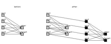
19.Units Copy Structure . . . (selection : dest?) Units Copy Structure All
Units Copy Structure Input Units Copy Structure Output Units Copy Structure None
Units Copy Structure . . . binding (selection : dest? site-popup) Units Copy Structure Back binding
Units Copy Structure Forward binding Units Copy Structure Double binding
These commands are re nements of the general Copy command. Here, all links between the selected units are always copied as well. This means that the substructure is copied form the originals to the new units. On a copy without Structure
116 |
CHAPTER 6. GRAPHICAL NETWORK EDITOR |
these links would go unnoticed. There are also options, which additional links are to be copied. If only the substructure is to be copied, the command Units Copy Structure None is used.
Figure 6.2: An Example for Units Copy Structure with Forward binding
The options with binding present a special feature. There, links between original and copied units are inserted automatically, in addition to the copied structure links. Back, Forward and Double specify thereby the direction of the links, where \back" means the direction towards the original unit. An example is shown in picture 6.2. If sites are used, the connections to the originals are assigned to the site selected in the popup. If not all originals have a site with that name, not all new units are linked to their predecessors.
With these various copy options, large, complicated nets with the same or similar substructures can be created very easily.
20.Mode Units (:) Mode Links (:)
Switches to the mode Units or Links. All sequences of the normal modes are available. The keys U and L need not be pressed anymore. This shortens all sequences by one key.
21.Units . . . Return (:) Links . . . Return (:)
Returns to normal mode after executing Mode Units.
22.Graphics All (:) Graphics Complete (:) Graphics Units (:) Graphics Links (:)
6.6. EXAMPLE DIALOGUE |
117 |
These commands initiate redrawing of the whole net, or parts of the net. With the exception of Graphics Complete, all commands a ect only the current display. They are especially useful after links have been deleted.
23.Graphic Direction ([unit] : )
This command assigns arrowheads to all links leading to/from the unit selected by the mouse. This is done independently from the setup values. XGUI, however, does not recall that links have been drawn. This means that, after moving a unit, these links remain in the window, if the display of links is switched o in the SETUP.
24.Graphics Move (TARGET [empty]/[unit] :)
The origin of the window (upper left corner) is moved in a way that the target unit in the info panel becomes visible at the position speci ed by the mouse.
25.Graphics Origin ([empty]/[unit] :)
The position speci ed by the mouse becomes new origin of the display (upper left corner).
26.Graphics Grid (:)
This command draws a point at each grid position. The grid, however, is not refreshed, therefore one might have to redo the command from time to time.
6.6Example Dialogue
A short example dialogue for the construction of an XOR network might clarify the use of the editor. First the four units are created. In the info panel the target name \input" and the Target bias \0" is entered.
Status Display |
Command |
Remark |
> |
Mode Units |
switch on mode units |
Units> |
|
set mouse to position (3,5) |
Units> |
Insert Target |
insert unit 1 with the attributes |
|
|
of the Target unit here. |
|
|
repeat for position (5,5). |
Units> |
|
name = \hidden", bias = ;2:88 |
Units> |
Insert Target |
position (3,3) insert unit 3 |
Units> |
|
name = \output", bias = ;3:41 |
Units> |
Insert Target |
position (3,1) insert unit 4 |
Units> |
Return |
return to normal mode |
> |
Mode Links |
switch on mode links |
Links> |
|
select both input units |
|
|
and set mouse to third unit |
118 |
|
CHAPTER 6. GRAPHICAL NETWORK EDITOR |
|
|
(\hidden") |
Links> |
|
specify weight \6:97" |
Links> |
Make to Target |
create links |
Links> |
|
set mouse to unit 4 (\output") |
|
|
specify weight \;5:24" |
Links> |
Make to Target |
create links |
Links> |
|
deselect all units and |
|
|
select unit 3 |
Links> |
|
set mouse to unit 4 and |
|
|
specify \11:71" as weight. |
Links> |
Make to Target |
create links |
Now the topology is de ned. The only actions remaining are to set the IO types and the four patterns. To set the IO types, one can either use the command Units Set Default io-type, which sets the types according to the topological position of the units, or repeatedly use the command Units Set io-Type. The second option can be aborted by pressing the Done button in the popup window before making a selection.