

Параллельные Процессы и Параллельное Программирование / SNNSv4.2.Manual
.pdf5.4. PATTERNS WITH CLASS INFORMATION AND VIRTUAL PATTERN SETS99
Example
The Pattern le
SNNS pattern definition file V4.2 generated at Tue Aug 3 00:00:44 1999
No. of patterns : 6
No. of input units : 3
No. of output units : 3
No. of classes : 2
Class redistribution : [ 2 1 ]
#Pattern 1: 0 0 1 1 0 0
#Class:
B
#Pattern 2: 0 1 0 1 0 1
#Class:
A
#Pattern 3: 0 1 1 0 0 0
#Class:
A
#Pattern 4: 1 0 0 0 0 1
#Class:
A
#Pattern 5: 1 0 1 1 1 0
#Class:
B
#Pattern 6: 1 1 0 1 1 1
#Class:
B
Would de ne a virtual pattern set with 12 patterns. There are 4 patterns of class B and 2 patterns of class A. Since the string A is alpha-numerically smaller than B it gets the rst redistribution value (\2") assigned, B gets assigned \1" respectively. Since now for each 1

100 |
CHAPTER 5. HANDLING PATTERNS WITH SNNS |
B there must be 2 As and each pattern has to be used at least once, this makes for a total of 2*4 A + 4 B = 12 patterns. Since there are only 6 patterns physically present, some of the patterns will be trained multiple times in each epoch (here the two A patterns are used 4 times).
Each group of patterns with the given class redistribution is called a \chunk group". This term is used during further explanations. For the given example and without pattern shu ing, the virtual pattern le would look like a pattern le with 12 patterns, occuring in the following order:
virtual (user visible) pattern number |
1 |
2 |
3 |
4 |
5 |
6 |
7 |
8 |
9 |
10 |
11 |
12 |
physical ( led) pattern number |
3 |
1 |
4 |
3 |
2 |
4 |
3 |
5 |
4 |
3 |
6 |
4 |
|
|
|
|
|
|
|
|
|
|
|
|
|
class |
A |
B |
A |
A |
B |
A |
A |
B |
A |
A |
B |
A |
|
|
|
|
|
|
|
|
|
|
|
|
|
Within each chunk group the patterns are arranged in such an order, that that classes are intermixed as much as possible.
With pattern shu ing enabled, the composition of 2 As and 1 B within one chunk group remains the same. In addition, the order of all As and Bs is shu ed, which could lead to the following virtual training order (shu ing is not visible to the user and takes place only during training):
virtual (user visible) pattern number |
1 |
2 |
3 |
4 |
5 |
6 |
7 |
8 |
9 |
10 |
11 |
12 |
physical ( led) pattern number |
3 |
5 |
4 |
4 |
1 |
3 |
4 |
2 |
3 |
3 |
6 |
4 |
|
|
|
|
|
|
|
|
|
|
|
|
|
class |
A |
B |
A |
A |
B |
A |
A |
B |
A |
A |
B |
A |
|
|
|
|
|
|
|
|
|
|
|
|
|
Note, that also during shu ing, a pattern is never used twice unless all other patterns within the same class were used at least once. This means that an order like
3 |
1 |
3 |
4 |
2 |
4 |
. . . |
A |
B |
A |
A |
B |
A |
A B A |
|
|
|
|
|
|
|
can never occur because the second A (physical pattern 3) is used twice before using pattern 4 once.
The unshu ed, virtual pattern order is visible to the user if class redistribution is activated, either through the optional Class redistribution eld in the pattern le or through the CLASSES panel. Activation of class redistribution results in a dynamic, virtual change
of the pattern set size whenever values from the CLASSES panel are altered. Also the virtual pattern order changes after alteration.
All virtualization is transparent to the user interface (e.g.  ,
,  buttons in the CONTROL panel) to all learn, update, and init functions of SNNS, as well as to the result le creation. Saving pattern les, however, results in a physical pattern composition together with de ned values in the Class redistribution eld.
Without the Class redistribution in the pattern le, or when switching the class usage o in xgui or batchman, the virtual (visible) pattern set will be identical to the patterns given in the physical pattern le.
5.5. PATTERN REMAPPING |
101 |
PLEASE NOTE:
At this time, the classical applications for class information, namely Kohonen and DLVQ learning, do not take advantage of this class information within the learning algorithm! This is due to the fact that classes were introduced to SNNS long after those learning schemes were implemented. Look for future releases of SNNS where there might be new implementations of these algorithms with classes.
Currently, class information is used only to de ne virtual pattern sets where the size of the virtual set is di erent from the size of the physical set.
5.5Pattern Remapping
Output values of patterns in SNNS main memory can also be dynamically altered. This is done with the help of the pattern remapping functions. Default is no remapping, i.e. the pattern values are taken as read from the pattern le.
When remapping patterns, the number of output values always stays constant. Also the input values are never altered. Only the values for the output patterns can be changed.
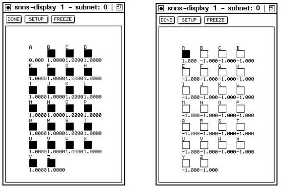
Figure 5.3: The e ect of invers pattern remapping
Figure 5.4: An example of threshold pattern remapping
With this remapping it becomes possible to quickly change a continuous output value pattern set to a binary one. Also patterns can easily be ipped, i.e. 0-s become 1-s and
102 |
CHAPTER 5. HANDLING PATTERNS WITH SNNS |
vice versa. Another possibility is to normalise the output pattern if necessary.
For the well known letters example (see also gure 3.4 and gure 4.7) the application of Invers pattern remapping is depicted in gure 5.3, the application of threshold remapping with parameters 0.5, 0.5, -1, 1 in gure 5.4.
SNNS comes with a set of prede ned remapping function we found to be useful. See section 4.7 for a description of the already implemented functions. For other purposes, this set can be easily extended, with almost unlimited possibilities. See chapter 15 of the implementation manual for details.
Chapter 6
Graphical Network Editor
The graphical user interface of SNNS has a network editor built in. With the network editor it is possible to generate a new network or to modify an existing network in various ways. There also exist commands to change the display style of the network.
As an introduction, operations on networks without sites will be discussed rst, since they are easier to learn and understand. Operations that have a restricted or slightly di erent meaning for networks with sites are displayed with the extension (Sites!) in the following overview. These changes are discussed in detail in section 6.5.
As usual with most applications of X-Windows, the mouse must be in the window in which an input is to appear. This means that the mouse must be in the display window for editor operations to occur. If the mouse is moved in a display, the status indicator of the manager panel changes each time a new raster position in the display is reached.
Di erent displays of a network can be seen as di erent views of the same object. This means that all commands in one display may a ect objects (units, links) in the other displays. Objects are moved or copied in a second display window in the same way as they are moved or copied in the rst display window.
The editor operations are usually invoked by a sequence of 2 to 4 keys on the keyboard. They only take place when the last key of the command (e.g. deletion of units) is pressed. We found that for some of us, the fastest way to work with the editor was to move the mouse with one hand and to type on the keyboard with the other hand. Keyboard actions and mouse movement may occur at the same time, the mouse position is only relevant when the last key of the sequence is pressed.
The keys that are su cient to invoke a part of a command are written in capital letters in the commands. The message line in the manager panel indicates the completed parts of the command sequence. Invalid keys are ignored by the editor.
As an example, if one presses the keys U for Units and C for Copy the status line changes as follows:
status line |
command |
comment |
> |
Units |
operation on units |
104 |
|
CHAPTER 6. GRAPHICAL NETWORK EDITOR |
Units> |
Copy |
copying of units |
Units Copy> |
|
(the sequence is not completed yet) |
To the left of the caret the fully expanded input sequence is displayed. At this place also a message is displayed when a command sequence is accepted and the corresponding operation is called. This serves as feedback, especially if the operation takes some time. If the operation completes quickly, only a short icker of the text displayed can be seen. Some error messages appear in the con rmer, others in the message line.
6.1Editor Modes
To work faster, three editor modes have been introduced which render the rst key unnecessary. In normal mode all sequences are possible, in unit mode all sequences that deal with units (that start with U), and in link mode all command sequences that refer to links (i.e. start with L).
Example (continued from above):
status line |
command |
comment |
Units Copy> |
Quit |
the input command may be cancelled |
|
|
any time |
> |
Mode |
|
Mode> |
Units |
enter unit mode |
Units> |
Copy |
copying . . . |
Units Copy> |
Quit |
cancel again |
Units> |
|
Quit leaves the current mode unchanged |
Units> |
Copy |
copying . . . |
Units Copy> |
Return |
return to normal mode |
> |
|
|
The mode command is useful, if several unit or link commands are given in sequence. Return cancels a command, like Quit does, but also returns to normal mode.
6.2Selection
6.2.1Selection of Units
Units are selected by clicking on the unit with the left mouse button. On Black&White terminals, selected units are shown with crosses, on color terminals in a special, user de ned, color. The default is yellow. By pressing and holding the mouse button down and moving the mouse, all units within a rectangular area can be selected, like in a number of popular drawing programs. It is not signi cant in what direction the rectangle is opened.
6.3. USE OF THE MOUSE |
105 |
To remove a unit or group of units from a selection, one presses the SHIFT key on the keyboard while selecting the unit or group of units again. This undoes the previous selection for the speci ed unit or group of units. Alternatively, a single unit can be deselected with the right mouse button.
If the whole selection should be reset, one clicks in an empty raster position. The number of selected units is displayed at the bottom of the manager panel next to a stylized selection icon.
Example (setting activations of a group of units):
The activations of a group of units can be set to a speci c value as follows: Enter the value in the activation value eld of the target unit in the info panel. Select all units that should obtain the new value. Then enter the command to set the activation (Units Set Activation).
6.2.2Selection of Links
Since it is often very hard to select a single link with the mouse in a dense web of links, in this simulator all selections of links are done with the reference to units. That is, links are selected via their source and target units. To select a link or a number of links, rst a unit or a group of units must be selected in the usual way with the left mouse button (indicated by crosses through the units). Then the mouse pointer is moved to another unit. All links between the selected set of units and the unit under the mouse pointer during the last key stroke of the link command are then selected.
Example (deleting a group of links):
All links from one unit to several other units are deleted as follows: First select all target units, then point to the source unit with the mouse. Now the command Links Delete from Source unit deletes all the speci ed links.
As can be seen from the examples, for many operations three types of information are relevant: rst a group of selected units, second the position of the mouse and the unit associated with this position and third some attributes of this unit which are displayed in the info panel. Therefore it is good practise to keep the info panel visible all the time.
In section 6.6 a longer example dialogue to build the well known XOR network (see alsogure 3.1) is given which shows the main interaction principles.
6.3Use of the Mouse
Besides the usual use of the mouse to control the elements of a graphical user interface (buttons, scroll bars etc.) the mouse is heavily used in the network editor. Many important functions like selection of units and links need the use of the mouse. The mouse buttons of the standard 3 button mouse are used in the following way within a graphic window:
left mouse button:
106 |
CHAPTER 6. GRAPHICAL NETWORK EDITOR |
Selects a unit. If the mouse is moved with the button pressed down, a group of units in a rectangular area is selected. If the SHIFT key is pressed at the same time, the units are deselected. The direction of movement with the mouse to open the rectangular area is not signi cant, i.e. one can open the rectangle from bottom right to top left, if convenient.
If the left mouse button is pressed together with the CONTROL key, a menu appears with all alternatives to complete the current command sequence. The menu items that display a trailing '!' indicate that the mouse position of the last command of a command sequence is important. The letter 'T' indicates that the target unit in the info panel plays a role. A (~) denotes that the command sequence is not yet completed.
right mouse button:
Undo of a selection. Clicking on a selected unit with the right mouse button only deselects this unit. Clicking on an empty raster position resets the whole selection.
middle mouse button:
Selects the source unit (on pressing the button down) and the target unit (on releasing the button) and displays them both in the info panel. If there is no connection between the two units, the target unit is displayed with its rst source unit. If the button is pressed on a source unit and released over an empty target position, the link between the source and the current (last) target is displayed. If there is no such link the display remains unchanged. Conversely, if the button is pressed on an empty source position and released on an existing target unit, the link between the current (last) source unit and the selected target unit is displayed, if one exists. This is a convenient way to inspect links.
In order to indicate the position of the mouse even with a small raster size, there is always a sensitive area of at least 16x16 pixels wide.
6.4Short Command Reference
The following section brie y describes the commands of the network editor. Capital letters denote the keys that must be hit to invoke the command in a command sequence.
The following commands are possible within any command sequence
Quit: quit a command
Return: quit a command and return to normal mode (see chapter 6.1)
Help: get help information. A help window pops up (see chapter 4.3.11)
As already mentioned, some operations have a di erent meaning if there exist units with sites in a network. These operations are indicated with the su x (Sites!) and are described in more detail in chapter 6.5. Commands that manipulate sites are also included in this overview. They start with the rst command Sites.
6.4. SHORT COMMAND REFERENCE |
107 |
Flags Safety: sets/resets safety ag (a ag to prompt the user before units or links are deleted additional question, if units with di erent subnet numbers are selected.)
1.Link Commands:
Links Set: sets all links between the selected units to the weight displayed in the info panel (independent of sites)
Links Make ...: creates or modi es connections
Links Make Clique: connects every selected unit with every other selected unit (Sites!)
Links Make to Target unit: creates links from all selected source units to a single target unit (under the mouse pointer) (Sites!)
Links Make from Source unit: creates links from a single source unit (under the mouse pointer) to all selected target units (Sites!)
Links Make Double: doubles all links between the selected units, i.e. generates two links (from source to target and from target to source) from each single link) (Sites!)
Links Make Invers: changes the direction of all links between the selected units (Sites!)
Links Delete Clique: deletes all links between all selected units (Sites!)
Links Delete to Target unit: deletes all incoming links from a selected group of units to a single target unit (under the mouse pointer) (Sites!)
Links Delete from Source unit: deletes all outgoing links from a single source unit (under the mouse pointer) to a selected group of units (Sites!)
Links Copy Input: copies all input links leading into the selected group of units as new input links to the target unit (under the mouse pointer) (Sites!)
Links Copy Output: copies all output links starting from the selected group of units as new output links of the source unit (under the mouse pointer) (Sites!).
Links Copy All: copies all input and output links from the selected group of units as new input or output links to the unit under the mouse pointer (Sites!)
Links Copy Environment: copies all links between the selected units and the TARGET unit to the actual unit, if there exist units with the same relative distance (Sites!)
2.Site Commands:
Sites Add: add a site to all selected units
Sites Delete: delete a site from all selected units
108 |
CHAPTER 6. GRAPHICAL NETWORK EDITOR |
Sites Copy with No links: copies the current site of the Target unit to all selected units. Links are not copied
Sites Copy with All links: ditto, but with all links
3.Unit Commands:
Units Freeze: freeze all selected units
Units Unfreeze: reset freeze for all selected units
Units Set Name: sets name to the name of Target
Units Set io-Type: sets I/O type to the type of Target
Units Set Activation: sets activation to the activation of Target
Units Set Initial activation: sets initial activation to the initial activation of Target
Units Set Output: sets output to the output of Target
Units Set Bias: sets bias to the bias of Target
Units Set Function Activation: sets activation function. Note: all selected units loose their default type (f-type)
Units Set Function Output: sets output function Note: all selected units loose their default type (f-type)
Units Set Function Ftype: sets default type (f-type)
Unitslinks Insert Default: inserts a unit with default values. The unit has no
Units Insert Target: inserts a unit with the same values as the Target unit. The unit has no links
Units Insert Ftype: inserts a unit of a certain default type (f-type) which is determined in a popup window
Units Delete: deletes all selected units
Units Move: all selected units are moved. The mouse determines the destination position of the TARGET unit (info-panel). The selected units and their position after the move are shown as outlines.
Units Copy ...: copies all selected units to a new position. The mouse position determines the destination position of the TARGET unit (info-panel).
Units Copy All: copies all selected units with all links
Units Copy Input: copies all selected units with their input links
Units Copy Output: copies all selected units and their output links
Units Copy None: copies all selected units, but no links