

2004-bomber-en
.pdf
|
|
|
|
Technical information |
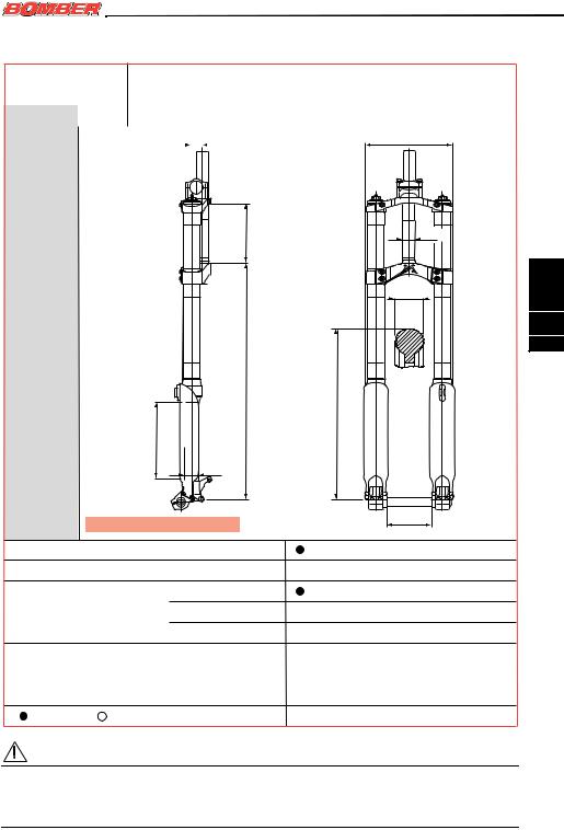
Table 9: Shiver SC |
|
|
|
|
|
|
|
|
|
TRAVEL (C) |
mm |
|
100 |
|
A (max) |
mm |
|
482 |
|
|
|
|
|
|
A (min) |
mm |
|
382 |
|
|
|
15 |
187 |
|
ø 30
Max 68
Shiver SC |
A |
345 |
ø 30 |
|
Max |
C |
|
|
|
|
|
|
|
|
112 |
||
|
|
|
|
|
|
135 |
||
|
|
|
|
|
|
|
|
|
|
Disk brake mounts |
|
|
|
XC International Standard for 6” disk |
|||
|
V-brake fit |
|
|
|
|
|
|
|
|
|
|
|
|
|
|
|
|
|
|
|
|
|
|
|
|
|
|
Drop out type |
|
|
Standard |
Ø 20 mm dedicated axle |
|||
|
|
|
|
QR 20 Plus |
|
|
|
|
|
|
|
|
|
|
|
||
|
|
|
|
|
|
|
|
|
|
|
|
|
QR 20 With Bolt |
|
|
|
|
|
|
|
|
|
|
|
||
|
Accessories |
|
|
|
|
|
|
|
|
|
|
|
|
|
|
|
|
|
|
|
|
|
|
|
|
|
|
= current |
= option |
|
|
= not available |
|
|
|
|
|
|
|
|
|
|||
|
ATTENTION |
|
|
|
|
|
|
|
|
Marzocchi reserves the right to modify data and features quoted in the table here above, if |
|||||||
1 |
needed for technical and/or commercial requirements. The dimensions indicated in the |
|||||||
_ |
drawing are only given as indicative. |
|
|
|
||||
MZ009 |
Please check on the internet page www.marzocchi.com for updated information. |
|||||||
|
||||||||
English
2
109

English
2
110
Technical information |
|
|
|
|
Table 10: Junior T & Super T PRO |
|
|
|
|
TRAVEL (C) |
mm |
|
|
170 |
A (max) |
mm |
|
|
558 |
A (min) |
mm |
|
|
388 |
|
18 |
|
|
181 |
|
|
|
|
ø 30 |
PRO |
|
Max184 |
|
|
T |
|
|
|
|
Super |
C |
|
|
|
|
ø 32 |
|
|
Max 68 |
|
|
|
|
|
Junior T & |
|
A |
352 |
Max345 |
|
|
|
|
100 * |
|
*: 110 with QR20 Drop outs |
|
|
130 |
|
|
|
|
|
Disk brake mounts |
|
|
|
XC International Standard for 6” disk |
|
|
||||||
V-brake fit |
|
|
|
|
|
|
|
|
|
|
|
|
|
|
|
|
|
|
|
|
|
|
|
|
|
|
|
|
|
|
|
|
|
|
|
|
|
|
Drop out type |
|
|
Standard |
|
|
|
|
|
|
|
|
|
|
|
|
|
|
|
|
|
|
|
|||
|
|
|
QR 20 Plus |
|
|
|
|
|
|
|
|
|
|
|
|
|
|
|
|
|
|
|
|
|
|
|
|
|
QR 20 With Bolt |
|
|
|
|
|
|
|
|
|
Accessories |
|
|
|
|
Integrated fender |
|
||||||
|
|
|
|
|
Direct mount handlebar clamp |
|
||||||
|
|
|
|
|
|
(long or short) |
|
|||||
|
|
|
|
|
|
|
|
|
|
|
|
|
= current |
= option |
|
|
= not available |
Junior T |
|
|
Super T PRO |
|
|
||
|
|
|
|
|
||||||||
ATTENTION |
|
|
|
|
|
|
|
|
|
|
|
|
Marzocchi reserves the right to modify data and features quoted in the table here above, if |
|
|
||||||||||
needed for technical and/or commercial requirements. The dimensions indicated in the |
1 |
|||||||||||
drawing are only given as indicative. |
|
|
|
|
|
|
|
_ |
||||
Please check on the internet page www.marzocchi.com for updated information. |
|
MZ009 |
||||||||||
|
||||||||||||
|
|
|
|
|
|
|
|
Technical information |
Table 11: Shiver DC |
|
|
|
|
|
|
|
|
|
|
|
|
|
||||
|
TRAVEL (C) |
mm |
|
|
|
|
|
190 |
|
A (max) |
mm |
|
572 |
||||
|
|
|
|
|
||||
|
A (min) |
mm |
|
382 |
||||
|
|
|
|
|
|
|
25 |
208 |
|
|
|
|
|
|
|
|
|
145* |
ø 30 |
|
Max |
||
|
Shiver DC |
Max 68 |
|
A |
||
|
||
|
Max345 |
|
|
C |
|
|
ø 35 |
English
2
111
* : 163 with high crown
110
Disk brake mounts |
|
|
|
XC International Standard for 6” disk |
|||
V-brake fit |
|
|
|
|
|
|
|
|
|
|
|
|
|
|
|
|
|
|
|
|
|
|
|
Drop out type |
|
|
Standard |
Ø 20 mm dedicated axle |
|||
|
|
|
QR 20 Plus |
|
|
|
|
|
|
|
|
|
|
||
|
|
|
|
|
|
|
|
|
|
|
QR 20 With Bolt |
|
|
|
|
|
|
|
|
|
|
||
Accessories |
|
|
|
|
Direct mount handlebar clamp |
||
|
|
|
|
|
(long or short) |
||
|
|
|
|
|
|
|
|
= current |
= option |
|
|
= not available |
|
|
|
|
|
|
|
|
|||
|
|
|
|
|
|
|
|
MZ009_1
ATTENTION
Marzocchi reserves the right to modify data and features quoted in the table here above, if needed for technical and/or commercial requirements. The dimensions indicated in the drawing are only given as indicative.
Please check on the internet page www.marzocchi.com for updated information.

English
2
112
Technical information
Table 12: 888 Series
TRAVEL (C) |
mm |
170 |
200 |
A (max) |
mm |
575 |
605 |
A (min) |
mm |
405 |
405 |
|
|
17,5 |
202 |
|
|
|
|
|
|
|
ø 30 |
|
|
Max160 |
|
Series |
ø 35 |
C |
|
|
|
|
|
|
|
|
|
|
Max 73 |
|
888 |
|
A |
|
|
|
|
|
Max357 |
|
|
|
|
110 |
|
|
|
|
145 |
|
Disk brake mounts |
|
XC International Standard for 6” disk |
|
|
V-brake fit |
|
|
|
|
Drop out type |
|
Standard |
Ø 20 mm dedicated axle |
|
|
|
QR 20 Plus |
|
|
|
|
QR 20 With Bolt |
|
|
Accessories |
|
|
Direct mount handlebar clamp |
|
|
|
|
Integrated fender |
|
= current |
= option |
= not available |
|
|
ATTENTION |
|
|
|
|
Marzocchi reserves the right to modify data and features quoted in the table here above, if |
|
|||
needed for technical and/or commercial requirements. The dimensions indicated in the |
1 |
|||
drawing are only given as indicative. |
|
_ |
||
Please check on the internet page www.marzocchi.com for updated information. |
MZ009 |
|||
|
||||

|
|
|
Technical information |
Table 13: Monster Series |
|
|
|
TRAVEL (C) |
mm |
200 (Monster) |
300 (Super Monster) |
A (max) |
mm |
593 |
693 |
A (min) |
mm |
393 |
393 |
|
|
34 |
225 |
|
|
190 |
|
|
|
Max |
ø 30 |
|
|
|
|
Series |
|
|
ø 40 |
|
C |
Max 73 |
|
|
|
|
|
Monster |
|
A |
357 |
|
|
|
Max |
|
|
|
|
|
|
|
|
|
110 |
|
|
|
|
|
|
|
|
|
|
|
|
|
|
|
|
|
|
|
|
||
|
|
|
|
|
|
|
|
|
|
|
|
|
|
||
|
|
|
|
|
|
|
|
175 |
|
|
|
|
|
||
|
|
|
|
|
|
|
|
|
|
|
|||||
|
|
Disk brake mounts |
|
|
|
DH International Standard for 8” disk |
|
||||||||
|
|
|
|
|
|
|
Rear calliper mount |
|
|||||||
|
|
|
|
|
|
|
|
|
|
|
|
|
|
|
|
|
|
V-brake fit |
|
|
|
|
|
|
|
|
|
|
|
|
|
|
|
|
|
|
|
|
|
|
|
|
|
|
|
|
|
|
|
|
|
|
|
|
|
|
|
|
|
||||
|
|
Drop out type |
|
|
Standard |
Ø 20 mm dedicated axle |
|
||||||||
|
|
|
|
|
QR 20 Plus |
|
|
|
|
|
|
|
|
|
|
|
|
|
|
|
|
|
|
|
|
|
|
|
|
||
|
|
|
|
|
|
|
|
|
|
|
|||||
|
|
|
|
|
QR 20 With Bolt |
|
|
|
|||||||
|
|
|
|
|
|
|
|||||||||
|
|
Accessories |
|
|
|
|
Direct mount handlebar clamp |
||||||||
|
|
|
|
|
|
|
|
(long or short) |
|||||||
|
|
|
|
|
|
|
|
|
|
|
|||||
|
|
= current |
= option |
|
|
= not available |
|
|
|
||||||
|
|
|
|
|
|||||||||||
|
|
ATTENTION |
|
|
|
|
|
|
|
|
|
|
|
|
|
|
Marzocchi reserves the right to modify data and features quoted in the table here above, if |
|
|||||||||||||
1 |
needed for technical and/or commercial |
requirements. The dimensions indicated in the |
|||||||||||||
_ |
drawing are only given as indicative. |
|
|
|
|
|
|
|
|
|
|||||
MZ009 |
Please check on the internet page www.marzocchi.com for updated information. |
|
|||||||||||||
|
|||||||||||||||
English
2
113

English
2
114
Technical information
2.2Fork’s internal components and fork’s operation
Inside MARZOCCHI forks you will find coil springs or air as a spring system.
The damping load that is generated during the fork legs compression and rebound, can be adjusted by cartridges, controlled by external adjusters, or by special hydraulic valve pumping rods, which operate according to compression speed (Speed Sensitive Valving).
Pumping rods can be controlled by external or internal adjusters, or they can have a fixed setting.
Cartridges and pumping rods are fully plunged in oil (Open Bath System). This system provides proper lubrication and cooling of the inner sliding parts; furthermore, the oil volume works as a damping and setting element.
The Open Bath system reduces the maintenance frequency compared to a sealed cartridge system.
Stanchion tubes are guided in the sliders by two teflon-coated bushings, free from static friction.
The seal system prevents oil leaks and contamination from particles entering the fork. It uses a special dual-lip oil seal and a dust seal at the top of each slider.
You will find here below the different fork damping systems:
ECC5: the new Extension Control Cartridge offers on-the-fly adjustment of the rebound damping with a 5-position clicker. Use the fast rebound position for downhilling, the 3 middle positions for race start sprints and rough climbing and the fully closed ECC position for steep dirt switchback climbs or Marathon style road climbs.
ETA: the new Extension Travel Adjustment locks down the rebound damping like the standard ECC, but still allows 25 - 30 mm of travel.
HSCV: the High-Speed Compression Valve (HSCV) allows lighter damping for better trail sensitivity but still resists bottoming. It is the best
way to provide a controlled damping environment for consistent and perfect damping. The moving valve on the shaft controls rebound and low-speed compression damping. The special valve in the bottom of the cartridge (HSCV), takes the edge of any hard hit to maintain control.
SSV: the Speed Sensitive Valve (SSV) uses 5 valve circuits to control damping rates based on the fork’s compression and rebound speed as well as the fork’s position in the travel.
SSVF: The latest version of our Speed Sensitive Valve has a new Floating valve and spring design. It incorporates a spring-loaded valve, which is more responsive and uses an external rebound adjuster.
MZ009_1

|
|
Technical information |
|
Table 14: BOMBER forks damping systems |
|
||
|
|
|
|
Fork |
Damping system |
||
Right leg |
Left leg |
||
|
|||
Dirt Jumper I |
SSV pumping rod with external adjustment |
SSV non-adjustable pumping rod |
|
Dirt Jumper II |
SSV pumping rod with internal adjustment |
SSV non-adjustable pumping rod |
|
Dirt Jumper III |
SSV non-adjustable pumping rod |
SSV non-adjustable pumping rod |
|
Junior T |
SSV non-adjustable pumping rod |
SSV non-adjustable pumping rod |
|
Marathon S |
HSCV F/R hydraulic cartridge |
ETA cartridge |
|
Marathon SL |
ECC5 hydraulic cartridge |
Negative air cartridge |
|
Monster T |
F/R adjustment cartridge in the upper area |
Final F/A external adjustment |
|
and F/A in the lower area |
cartridge |
||
|
|||
MX Comp AIR |
SSV pumping rod with internal adjustment |
Non-adjustable pumping rod |
|
MX Comp COIL |
SSV pumping rod with internal adjustment |
SSV pumping rod with internal |
|
adjustment |
|||
|
|
||
MX Comp + ETA |
SSV pumping rod with internal adjustment |
ETA Cartridge |
|
MX Pro AIR |
SSVF pumping rod with external adjustment |
Non-adjustable pumping rod |
|
MX Pro COIL |
SSVF pumping rod with external adjustment |
Non-adjustable pumping rod |
|
MX Pro + ETA |
SSVF pumping rod with external adjustment |
ETA cartridge |
|
888 R |
HSCV F/R hydraulic cartridge |
Final F/A HSCV hydraulic |
|
cartridge |
|||
|
|
||
888 RR |
HSCV F/R hydraulic cartridge |
SSVF non-adjustable pumping |
|
rod |
|||
|
|
||
888 RT |
SSVF non-adjustable pumping rod |
SSVF non-adjustable pumping |
|
rod |
|||
|
|
||
Shiver DC |
HSCV F/R hydraulic cartridge |
HSCV F/R hydraulic cartridge |
|
Shiver SC |
HSCV F/R hydraulic cartridge |
HSCV F/R hydraulic cartridge |
|
Street DJ |
SSV non-adjustable pumping rod |
SSV non-adjustable pumping rod |
|
Super Monster |
F/R adjustment cartridge in the upper area |
Final F/A external adjustment |
|
and F/A in the lower area |
cartridge |
||
|
|||
Super T PRO |
HSCV F/R hydraulic cartridge |
HSCV F/R hydraulic cartridge |
|
Z1 Drop-Off I |
SSVF pumping rod with external adjustment |
ETA cartridge |
|
Z1 Drop-Off II |
SSV pumping rod with external adjustment |
Non-adjustable pumping rod |
|
Z1 Wedge |
SSV non-adjustable pumping rod |
SSV non-adjustable pumping rod |
|
Z1 FR |
HSCV F/R hydraulic cartridge |
ETA cartridge |
|
Z1 FR SL |
ECC5 hydraulic cartridge |
Negative air cartridge |
|
Z-150 DO |
SSVF pumping rod with external adjustment |
ETA cartridge |
|
Z-150 FR |
HSCV F/R hydraulic cartridge |
ETA cartridge |
|
Z-150 FR SL |
ECC5 hydraulic cartridge |
Negative air cartridge |
|
|
|
|
|
English
2
115
MZ009_1
F/A= compression braking
F/R= rebound (or extension) braking

English
3
116
Installation
33 INSTALLATION
3.1 Installing on the frame
The fork is supplied with “A-Head Set” (threadless) steer tube to be cut according to frame size it will be used on.
Installing the fork on the bicycle frame is a very delicate operation that must be carried out by specialized personnel.
ATTENTION
The assembling on the frame and the steer tube adjustment must be carried out in compliance with the manufacturer’s instructions. Improper installation may jeopardize the safety of the rider.
Marzocchi does not guarantee the installation and refuses all responsibility for damages and/or accidents that may be caused by an incorrect installation.
The steer tube must be pressed into the crown; its replacement must be carried out by one of our service centers only, using the required tools.
ATTENTION
In case of improper installation of the steer tube into the crown, the rider might lose control of his/her bicycle, thus jeopardizing his/her safety.
ATTENTION
On all dual crown MY 2004 BOMBER models, the lower crown is clamped to the stanchions (or to the sliders in the upsidedown models) through some bolts. In this case, you will have to respect following precautions during installing:
•In case of oversized diameter areas on the stanchions or on the sliders, the crowns clamping can only be done in these areas (as shown in the picture).
•In case of reference notches on the stanchions or on the sliders, the lower part of the lower crown must be positioned over the notch.
MZ002011

bottom face of the steering crown shall be greater than 4 mm.
•On the Monster forks the distance between the lower part of the lower crown and the dust seal must be bigger than 4 mm.
•In the dual crown models, the maximum length of the steering tube between the two crowns shall be less than the values
indicated in the following table
888 |
160 mm |
|
Junior T e Super T PRO |
184 mm |
|
Shiver DC (with standard steering |
145 mm |
|
crown) |
||
|
||
Shiver DC (with high steering crown) |
163 mm |
|
Monster Series |
190 mm |
|
|
|
•With the fork fully compressed, the distance between the inflated tyre and the
MZ009_1

|
|
|
|
|
|
|
|
|
Installation |
|
3.2 Installing the brake system |
|
|
• |
The transformation from one braking |
||||||
Installing the |
brake |
system is |
a very delicate |
|
system to the other must be done by |
|||||
|
qualified personnel. |
|||||||||
operation that must be carried out by |
|
|||||||||
• |
In the forks with assembled arch-slider |
|||||||||
specialized personnel. |
|
|
|
|||||||
|
|
|
|
|
|
|
|
|
(models for 29" wheel and Z1 Wedge), |
|
ATTENTION |
|
|
|
|
|
bolts (A) are not only used to fix the V- |
||||
Marzocchi does not guarantee the |
|
brake levers; they also contribute to lock |
||||||||
installation and accepts no liability for |
|
the upper part of the slider to the arch. In |
||||||||
damage and/or accidents arising from a |
|
the case of installation of a disk brake |
||||||||
wrong installation. |
|
|
|
|
|
system, the service centres can replace |
||||
Improper installation of the disk brake |
|
bolts (A) with screws (B). |
||||||||
system can overstress the caliper |
• |
The user is not allowed to remove bolts (A) |
||||||||
mountings, which may break. The |
|
or screws (B). |
||||||||
installation of |
the |
brake system |
must |
be |
• Do not replace screws (B) with commercial |
|||||
carried out following the instructions of the |
||||||||||
|
bolts. |
|||||||||
brake |
system |
manufacturer. |
Improper |
|
||||||
• |
On the thread of bolts (A, C) and screws |
|||||||||
installation can be dangerous for the rider. |
||||||||||
Use only brake systems in accordance with |
|
(B) a special anti-unscrewing treatment |
||||||||
the fork’s specifications considering that: |
|
|
has been applied; as a result, the removed |
|||||||
• All forks with ø32mm legs can only mount |
|
bolts cannot be re-used as they lose such |
||||||||
|
treatment. |
|||||||||
disk brakes. |
|
|
|
|
|
|
||||
|
|
|
|
|
• |
When a disk braking system is mounted, |
||||
• The |
forks |
with |
ø30mm |
legs |
can |
be |
||||
|
before any use, check that the brake tube |
|||||||||
equipped before delivery with disk brake |
|
|||||||||
mounts or V-brake mounts. |
is correctly fixed to the special mount (D, |
|
E). |
||
|
A
A
B |
C |
B
E
1 |
D |
MZ009 |
|
English
3
117

English
3
118
Installation
3.3Wheel installing with a standard fork’s end
ATTENTION
Install the wheel in compliance with the manufacturer’s instructions.
For correct fork function after wheel installing you will need to:
•check the correct fork-wheel alignment by fully compressing the fork a few times.
•lift the front wheel above the ground; turn the wheel a few times to verify the correct alignment with the disk brake or the V-brake pads.
3.4Wheel installing with a QR20 Plus fork
For correct fork function, please follow the instructions here below when installing the wheel:
•Release the securing system on both legs by pushing the levers (A) downwards and open the flap (P)
•For quick-release hubs, open the release lever (B).
•For threaded cap hubs, unscrew the cap (C) as much as needed to insert the wheel axle through the fork wheel axle clamp.
•Insert the wheel axle (D) through the fork wheel axle clamp.
•Make sure that the wheel axle supporting bushings (E) are centered in the sliders’ seat
•If the wheel axle is provided with quickrelease system, lock the wheel with the quickrelease lever (B); otherwise, tighten the cap positioned on the axle side using a 6 mm Allen key to the required tightening torque (see Table - Tightening Torques).
•Verify the correct settling of the supporting bushings (E)
•Check the correct fork-wheel alignment, by fully compressing the fork a few times.
•Lift the front wheel; turn the wheel a few times to verify the correct alignment with the disk brake.
•Lock the securing system by pulling the levers (A) upwards and adjust clearance through the adjusters (H), if needed.
|
P |
|
A |
|
E |
C |
B |
|
|
MZ001037 |
D |
|
|
E |
|
C |
A |
|
MZ001038 |
B |
|
H |
||
|
MZ009_1