

- •Features
- •Disclaimer
- •Overview
- •Block Diagram
- •Pin Descriptions
- •Port A (PA7..PA0)
- •Port B (PB7..PB0)
- •Port C (PC7..PC0)
- •Port D (PD7..PD0)
- •RESET
- •XTAL1
- •XTAL2
- •AVCC
- •AREF
- •Resources
- •Data Retention
- •AVR CPU Core
- •Introduction
- •Status Register
- •Stack Pointer
- •I/O Memory
- •Clock Systems and their Distribution
- •Clock Sources
- •Crystal Oscillator
- •External Clock
- •Idle Mode
- •Power-down Mode
- •Power-save Mode
- •Standby Mode
- •Analog Comparator
- •Brown-out Detector
- •Watchdog Timer
- •Port Pins
- •Resetting the AVR
- •Reset Sources
- •Power-on Reset
- •External Reset
- •Watchdog Reset
- •Watchdog Timer
- •Interrupts
- •I/O Ports
- •Introduction
- •Configuring the Pin
- •Reading the Pin Value
- •Unconnected pins
- •Alternate Port Functions
- •Register Description for I/O Ports
- •8-bit Timer/Counter0 with PWM
- •Overview
- •Registers
- •Definitions
- •Counter Unit
- •Normal Mode
- •Fast PWM Mode
- •8-bit Timer/Counter Register Description
- •Timer/Counter0 and Timer/Counter1 Prescalers
- •Internal Clock Source
- •Prescaler Reset
- •External Clock Source
- •16-bit Timer/Counter1
- •Overview
- •Registers
- •Definitions
- •Compatibility
- •Counter Unit
- •Input Capture Unit
- •Noise Canceler
- •Force Output Compare
- •Normal Mode
- •Fast PWM Mode
- •16-bit Timer/Counter Register Description
- •8-bit Timer/Counter2 with PWM and Asynchronous Operation
- •Overview
- •Registers
- •Definitions
- •Counter Unit
- •Normal Mode
- •Fast PWM Mode
- •8-bit Timer/Counter Register Description
- •Slave Mode
- •Master Mode
- •Data Modes
- •USART
- •Overview
- •Clock Generation
- •External Clock
- •Frame Formats
- •Parity Bit Calculation
- •Parity Generator
- •Receiver Error Flags
- •Parity Checker
- •Disabling the Receiver
- •Using MPCM
- •Write Access
- •Read Access
- •Features
- •TWI Terminology
- •Transferring Bits
- •Address Packet Format
- •Data Packet Format
- •Overview of the TWI Module
- •SCL and SDA Pins
- •Bus Interface Unit
- •Address Match Unit
- •Control Unit
- •Using the TWI
- •Master Receiver Mode
- •Slave Receiver Mode
- •Miscellaneous States
- •Analog Comparator Multiplexed Input
- •Analog to Digital Converter
- •Features
- •Operation
- •Changing Channel or Reference Selection
- •ADC Input Channels
- •Analog Input Circuitry
- •Features
- •Overview
- •TAP Controller
- •PRIVATE0; $8
- •PRIVATE1; $9
- •PRIVATE2; $A
- •PRIVATE3; $B
- •Bibliography
- •IEEE 1149.1 (JTAG) Boundary-scan
- •Features
- •System Overview
- •Data Registers
- •Bypass Register
- •Reset Register
- •EXTEST; $0
- •IDCODE; $1
- •AVR_RESET; $C
- •BYPASS; $F
- •Scanning the ADC
- •ATmega16 Boundary-scan Order
- •Features
- •Application Section
- •Read-While-Write and no Read- While-Write Flash Sections
- •Prevent Reading the RWW Section during Self-Programming
- •Simple Assembly Code Example for a Boot Loader
- •Fuse Bits
- •Latching of Fuses
- •Signature Bytes
- •Calibration Byte
- •Page Size
- •Signal Names
- •Chip Erase
- •Reading the Flash
- •Reading the EEPROM
- •Data Polling Flash
- •Data Polling EEPROM
- •AVR_RESET ($C)
- •PROG_ENABLE ($4)
- •Data Registers
- •Reset Register
- •Programming Enable Register
- •Programming Command Register
- •Virtual Flash Page Read Register
- •Performing Chip Erase
- •Reading the Flash
- •Reading the EEPROM
- •Electrical Characteristics
- •Absolute Maximum Ratings*
- •DC Characteristics
- •External Clock Drive Waveforms
- •External Clock Drive
- •Two-wire Serial Interface Characteristics
- •ADC Characteristics
- •Idle Supply Current
- •Pin Pullup
- •Pin Driver Strength
- •Register Summary
- •Instruction Set Summary
- •Ordering Information
- •Packaging Information
- •Errata
 ATmega16(L)
Table 106. Fuse Low Byte
Fuse Low |
Bit |
|
|
|
Byte |
No. |
Description |
Default Value |
|
|
|
|
|
|
BODLEVEL |
7 |
Brown-out Detector trigger level |
1 |
(unprogrammed) |
|
|
|
|
|
BODEN |
6 |
Brown-out Detector enable |
1 |
(unprogrammed, BOD disabled) |
|
|
|
|
|
SUT1 |
5 |
Select start-up time |
1 |
(unprogrammed)(1) |
SUT0 |
4 |
Select start-up time |
0 |
(programmed)(1) |
CKSEL3 |
3 |
Select Clock source |
0 |
(programmed)(2) |
CKSEL2 |
2 |
Select Clock source |
0 |
(programmed)(2) |
CKSEL1 |
1 |
Select Clock source |
0 |
(programmed)(2) |
CKSEL0 |
0 |
Select Clock source |
1 |
(unprogrammed)(2) |
Notes: 1. The default value of SUT1..0 results in maximum start-up time. SeeTable 10 on page 29 for details.
2.The default setting of CKSEL3..0 results in internal RC Oscillator @ 1MHz. See Table 2 on page 25 for details.
The status of the Fuse bits is not affected by Chip Erase. Note that the Fuse bits are locked if Lock bit1 (LB1) is programmed. Program the Fuse bits before programming the Lock bits.
Latching of Fuses The Fuse values are latched when the device enters programming mode and changes of the Fuse values will have no effect until the part leaves Programming mode. This does not apply to the EESAVE Fuse which will take effect once it is programmed. The fuses are also latched on Power-up in Normal mode.
Signature Bytes
Calibration Byte
All Atmel microcontrollers have a three-byte signature code which identifies the device. This code can be read in both serial and parallel mode, also when the device is locked. The three bytes reside in a separate address space.
For the ATmega16 the signature bytes are:
1.$000: $1E (indicates manufactured by Atmel)
2.$001: $94 (indicates 16KB Flash memory)
3.$002: $03 (indicates ATmega16 device when $001 is $94)
The ATmega16 stores four different calibration values for the internal RC Oscillator. These bytes resides in the signature row High Byte of the addresses 0x0000, 0x0001, 0x0002, and 0x0003 for 1, 2, 4, and 8 Mhz respectively. During Reset, the 1 MHz value is automatically loaded into the OSCCAL Register. If other frequencies are used, the calibration value has to be loaded manually, see “Oscillator Calibration Register – OSCCAL” on page 30 for details.
261
2466P–AVR–08/07
Page Size
Parallel
Programming
Parameters, Pin
Mapping, and
Commands
Signal Names
Table 107. No. of Words in a Page and no. of Pages in the Flash
Flash Size |
Page Size |
PCWORD |
No. of Pages |
PCPAGE |
PCMSB |
|
|
|
|
|
|
8K words (16K bytes) |
64 words |
PC[5:0] |
128 |
PC[12:6] |
12 |
|
|
|
|
|
|
Table 108. No. of Words in a Page and no. of Pages in the EEPROM
EEPROM Size |
Page Size |
PCWORD |
No. of Pages |
PCPAGE |
EEAMSB |
|
|
|
|
|
|
512 bytes |
4 bytes |
EEA[1:0] |
128 |
EEA[8:2] |
8 |
|
|
|
|
|
|
This section describes how to parallel program and verify Flash Program memory, EEPROM Data memory, Memory Lock bits, and Fuse bits in the ATmega16. Pulses are assumed to be at least 250 ns unless otherwise noted.
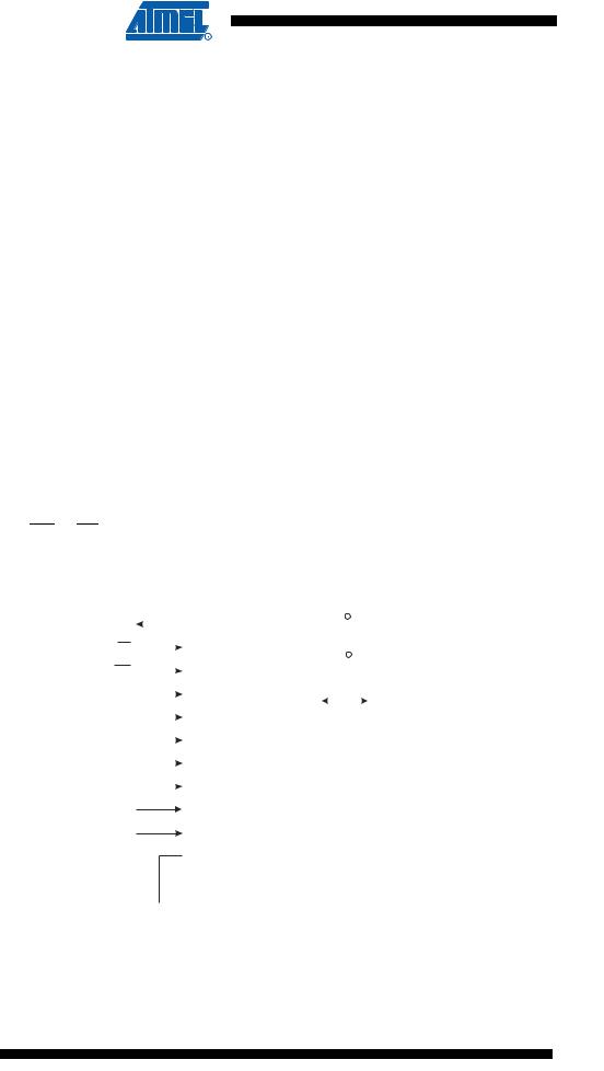
In this section, some pins of the ATmega16 are referenced by signal names describing their functionality during parallel programming, see Figure 127 and Table 109. Pins not described in the following table are referenced by pin names.
The XA1/XA0 pins determine the action executed when the XTAL1 pin is given a positive pulse. The bit coding is shown in Table 111.
When pulsing WR or OE, the command loaded determines the action executed. The different Commands are shown in Table 112.
Figure 127. Parallel Programming
|
|
|
|
|
|
|
|
|
|
|
|
|
|
|
|
|
|
|
|
|
|
+5V |
||
|
|
|
|
|
|
|
|
|
|
|
|
|
|
|
|
|
|
PD1 |
|
|||||
|
|
|
|
|
|
|
|
|
|
|||||||||||||||
RDY/BSY |
|
|
VCC |
|
|
|
|
|||||||||||||||||
|
|
|
|
|
|
|
|
|
|
|
|
|
|
|
|
|
|
|
|
|
|
|
|
|
|
|
|
|
|
|
|
|
|
|
|
|
|
|
|
|
|
|
|
|
|
+5V |
|||
|
|
|
|
|
|
|
|
|
|
|
|
|
|
|
|
|
|
|
|
|
|
|||
|
|
|
OE |
PD2 |
|
|
||||||||||||||||||
|
|
|
|
|
|
|
|
|||||||||||||||||
|
|
|
WR |
|
|
|
|
|
|
|
|
|
|
|
PD3 |
AVCC |
|
|
|
|
||||
|
|
|
|
|
|
|
|
|
|
|
|
|
|
|
|
|
|
|||||||
|
|
|
BS1 |
|
|
|
|
PD4 |
PB7 - PB0 |
|
|
|
DATA |
|||||||||||
|
|
|
|
|
||||||||||||||||||||
|
|
|
XA0 |
|
|
|
|
|
|
|
|
|
|
|
PD5 |
|
|
|
||||||
|
|
|
|
|
|
|
|
|
|
|
|
|||||||||||||
|
|
|
|
|
|
|
||||||||||||||||||
|
|
|
XA1 |
|
|
|
|
PD6 |
|
|
|
|
|
|||||||||||
|
|
|
|
|
|
|
||||||||||||||||||
|
PAGEL |
|
|
|
PD7 |
|
|
|
|
|
||||||||||||||
|
|
|
|
|
|
|
||||||||||||||||||
|
+12 V |
|
|
|
|
|
|
|
|
|
|
|
|
|||||||||||
|
|
|
|
|
|
|
|
|
|
|
|
RESET |
|
|
|
|
|
|||||||
|
|
|
|
|
|
|
|
|||||||||||||||||
|
|
|
BS2 |
|
PA0 |
|
|
|
|
|
||||||||||||||
|
|
|
|
|
|
|
|
|
|
|
|
|
|
|
|
|
|
XTAL1 |
|
|
|
|
|
|
|
|
|
|
|
|
|
|
|
|
|
|
|
|
|
|
|
|
|
|
|
|
|
||
|
|
|
|
|
|
|
|
|
|
|
|
|
|
|
|
|
|
GND |
|
|
|
|
|
|
|
|
|
|
|
|
|
|
|
|
|
|
|
|
|
|
|
|
|
|
|
|
|
|
|
|
|
|
|
|
|
|
|
|
|
|
|
|
|
|
|
|
|
|
|
|
|
|
|
|
|
|
|
|
|
|
|
|
|
|
|
|
|
|
|
|
|
|
|
|
|
|
|
|
|
|
|
|
|
|
|
|
|
|
|
|
|
|
|
|
|
|
|
|
|
|
|
|
|
|
262 ATmega16(L)
2466P–AVR–08/07

 ATmega16(L)
Table 109. Pin Name Mapping
|
Signal Name in |
|
|
|
|
|
||||
|
Programming Mode |
Pin Name |
I/O |
Function |
||||||
|
|
|
|
|
|
|
|
|
||
|
|
|
|
|
|
|
|
0: Device is busy programming, 1: Device is ready |
||
|
RDY/BSY |
PD1 |
O |
|||||||
|
for new command |
|||||||||
|
|
|
|
|
|
|
|
|||
|
|
|
|
|
|
|
||||
|
|
|
|
PD2 |
I |
Output Enable (Active low) |
||||
|
OE |
|||||||||
|
|
|
|
|
|
|||||
|
|
|
|
PD3 |
I |
Write Pulse (Active low) |
||||
|
WR |
|||||||||
|
|
|
|
|
|
|
|
|
||
|
BS1 |
PD4 |
I |
Byte Select 1 (“0” selects Low byte, “1” selects |
||||||
|
High byte) |
|||||||||
|
|
|
|
|
|
|
|
|||
|
|
|
|
|
||||||
|
XA0 |
PD5 |
I |
XTAL Action Bit 0 |
||||||
|
|
|
|
|
||||||
|
XA1 |
PD6 |
I |
XTAL Action Bit 1 |
||||||
|
|
|
|
|
||||||
|
PAGEL |
PD7 |
I |
Program Memory and EEPROM data Page Load |
||||||
|
|
|
|
|
|
|
|
|
||
|
BS2 |
PA0 |
I |
Byte Select 2 (“0” selects Low byte, “1” selects |
||||||
|
2’nd High byte) |
|||||||||
|
|
|
|
|
|
|
|
|||
|
|
|
|
|
|
|
||||
|
DATA |
PB7-0 |
I/O |
Bidirectional Data bus (Output when |
|
is low) |
||||
|
OE |
|||||||||
|
|
|
|
|
|
|
|
|
|
|
Table 110. Pin Values used to Enter Programming Mode
Pin |
Symbol |
Value |
|
|
|
PAGEL |
Prog_enable[3] |
0 |
|
|
|
XA1 |
Prog_enable[2] |
0 |
|
|
|
XA0 |
Prog_enable[1] |
0 |
|
|
|
BS1 |
Prog_enable[0] |
0 |
|
|
|
Table 111. XA1 and XA0 Coding
XA1 |
XA0 |
Action when XTAL1 is Pulsed |
|
|
|
0 |
0 |
Load Flash or EEPROM Address (High or low address byte determined by BS1) |
|
|
|
0 |
1 |
Load Data (High or Low data byte for Flash determined by BS1) |
|
|
|
1 |
0 |
Load Command |
|
|
|
1 |
1 |
No Action, Idle |
|
|
|
Table 112. Command Byte Bit Coding
Command Byte |
Command Executed |
|
|
1000 0000 |
Chip Erase |
|
|
0100 0000 |
Write Fuse Bits |
|
|
0010 0000 |
Write Lock Bits |
|
|
0001 0000 |
Write Flash |
|
|
0001 0001 |
Write EEPROM |
|
|
263
2466P–AVR–08/07

Table 112. Command Byte Bit Coding
Command Byte |
Command Executed |
|
|
0000 1000 |
Read Signature Bytes and Calibration byte |
|
|
0000 0100 |
Read Fuse and Lock bits |
|
|
0000 0010 |
Read Flash |
|
|
0000 0011 |
Read EEPROM |
|
|
264 ATmega16(L) 
2466P–AVR–08/07