

|
|
|
ATmega8(L) |
|
|
|
|
|
Slave Transmitter Mode |
|
|
|
In the Slave Transmitter mode, a number of data bytes are transmitted to a Master |
||
|
|||
|
|
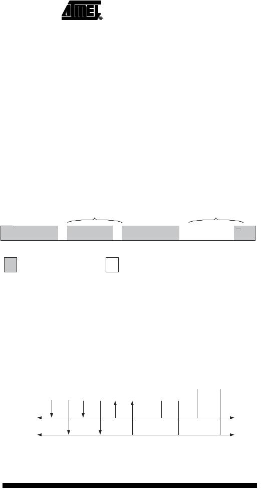
Receiver (see Figure 84). All the status codes mentioned in this section assume that the |
|
prescaler bits are zero or are masked to zero.
Figure 84. Data Transfer in Slave Transmitter Mode
|
|
|
|
|
|
|
|
|
|
|
|
|
|
|
VCC |
|
|
|
|
|
|
|
|
|
|
|
|
|
|
|
|
|
|
|
|
|
|
|
|
|
|
|
|
|
|
|
|
|
|
||
|
|
|
|
|
|
|
|
|
|
|
|
|
|
|
|
|
|
|
|
|
|
|
|
|
|
|
|
Device 1 |
|
Device 2 |
|
Device 3 |
........ |
|
|
|
|
|
|
|
|
|
|
|
|
||||||
|
|
|
|
Device n |
|
|
R1 |
|
R2 |
|
|
||||||||||||||
|
|
|
SLAVE |
|
|
MASTER |
|
|
|
|
|
|
|||||||||||||
|
|
TRANSMITTER |
|
|
RECEIVER |
|
|
|
|
|
|
|
|
|
|
|
|
|
|
|
|
|
|||
SDA |
|
|
|
|
|
|
|
|
|
|
|
|
|
|
|
|
|
|
|
|
|
|
|
|
|
|
|
|
|
|
|
|
|
|
|
|
|
|
|
|
|
|
|
|
|
|
|
|
|
|
|
|
|
|
|
|
|
|
|
|
|
|
|
|
|
|
|
|
|
|
|
|
|
|
|
|
|
|
|
|
|
|
|
|
|
|
|
|
|
|
|
|
|
|
|
|
|
|
|
|
|
|
|
|
|
|
|
|
|
|
|
|
|
|
|
|
|
|
|
|
|
|
|
|
|
|
|
|
|
|
|
|
|
|
|
|
|
|
|
|
|
|
|
|
|
|
|
|
|
|
|
|
|
|
|
SCL |
|
|
|
|
|
|
|
|
|
|
|
|
|
|
|
|
|
|
|
|
|
|
|
|
|
|
|
|
|
|
|
|
|
|
|
|
|
|
|
|
|
|
|
|
|
|
|
|
|
|
|
|
|
|
|
|
|
|
|
|
|
|
|
|
|
|
|
|
|
|
|
|
|
|
|
|
|
To initiate the Slave Transmitter mode, TWAR and TWCR must be initialized as follows:
TWAR |
|
TWA6 |
TWA5 |
TWA4 |
TWA3 |
TWA2 |
TWA1 |
TWA0 |
TWGCE |
|
|
|
|
|
|
|
|
|
|
value |
|
|
Device’s Own Slave Address |
|
|
|
|||
|
|
|
|
|
|
|
|
|
|
The upper seven bits are the address to which the Two-wire Serial Interface will respond when addressed by a Master. If the LSB is set, the TWI will respond to the general call address (0x00), otherwise it will ignore the general call address.
TWCR |
TWINT |
TWEA |
TWSTA |
TWSTO |
TWWC |
TWEN |
– |
TWIE |
value |
0 |
1 |
0 |
0 |
0 |
1 |
0 |
X |
|
|
|
|
|
|
|
|
|
TWEN must be written to one to enable the TWI. The TWEA bit must be written to one to enable the acknowledgement of the device’s own slave address or the general call address. TWSTA and TWSTO must be written to zero.
When TWAR and TWCR have been initialized, the TWI waits until it is addressed by its own slave address (or the general call address if enabled) followed by the data direction bit. If the direction bit is “1” (read), the TWI will operate in ST mode, otherwise SR mode is entered. After its own slave address and the write bit have been received, the TWINT Flag is set and a valid status code can be read from TWSR. The status code is used to determine the appropriate software action. The appropriate action to be taken for each status code is detailed in Table 69. The Slave Transmitter mode may also be entered if arbitration is lost while the TWI is in the Master mode (see state 0xB0).
If the TWEA bit is written to zero during a transfer, the TWI will transmit the last byte of the transfer. State 0xC0 or state 0xC8 will be entered, depending on whether the Master Receiver transmits a NACK or ACK after the final byte. The TWI is switched to the not addressed Slave mode, and will ignore the Master if it continues the transfer. Thus the Master Receiver receives all “1” as serial data. State 0xC8 is entered if the Master demands additional data bytes (by transmitting ACK), even though the Slave has transmitted the last byte (TWEA zero and expecting NACK from the Master).
While TWEA is zero, the TWI does not respond to its own slave address. However, the Two-wire Serial Bus is still monitored and address recognition may resume at any time by setting TWEA. This implies that the TWEA bit may be used to temporarily isolate the TWI from the Two-wire Serial Bus.
185
2486M–AVR–12/03

|
|
|
|
|
|
|
|
|
|
|
|
|
|
|
|
|
|
|
|
|
|
|
|
|
In all sleep modes other than Idle mode, the clock system to the TWI is turned off. If the |
||||||||||
|
TWEA bit is set, the interface can still acknowledge its own slave address or the general |
||||||||||
|
call address by using the Two-wire Serial Bus clock as a clock source. The part will then |
||||||||||
|
wake up from sleep and the TWI will hold the SCL clock will low during the wake up and |
||||||||||
|
until the TWINT Flag is cleared (by writing it to one). Further data transmission will be |
||||||||||
|
carried out as normal, with the AVR clocks running as normal. Observe that if the AVR is |
||||||||||
|
set up with a long start-up time, the SCL line may be held low for a long time, blocking |
||||||||||
|
other data transmissions. |
|
|
|
|
|
|
|
|
||
|
Note that the Two-wire Serial Interface Data Register – TWDR does not reflect the last |
||||||||||
|
byte present on the bus when waking up from these sleep modes. |
||||||||||
Table 69. Status Codes for Slave Transmitter Mode |
|
|
|
|
|
|
|
|
|
||
|
|
|
|
|
|
|
|
||||
Status Code |
|
Application Software Response |
|
|
|||||||
(TWSR) |
Status of the Two-wire Serial Bus |
|
|
To TWCR |
|
|
|||||
Prescaler Bits |
and Two-wire Serial Interface |
|
|
|
|
||||||
To/from TWDR |
STA |
STO |
|
TWINT |
TWEA |
|
|||||
are 0 |
Hardware |
|
Next Action Taken by TWI Hardware |
||||||||
|
|
||||||||||
|
|
|
|
|
|
|
|
|
|||
0xA8 |
Own SLA+R has been received; |
Load data byte or |
X |
0 |
|
|
|
1 |
|
0 |
Last data byte will be transmitted and NOT ACK should |
|
ACK has been returned |
|
|
|
|
|
|
|
|
|
be received |
|
|
Load data byte |
X |
0 |
|
|
|
1 |
|
1 |
Data byte will be transmitted and ACK should be re- |
|
|
|
|
|
|
|
|
|
|
|
ceived |
0xB0 |
Arbitration lost in SLA+R/W as |
Load data byte or |
X |
0 |
|
|
|
1 |
|
0 |
Last data byte will be transmitted and NOT ACK should |
|
Master; own SLA+R has been |
|
|
|
|
|
|
|
|
|
be received |
|
received; ACK has been returned |
Load data byte |
X |
0 |
|
|
|
1 |
|
1 |
Data byte will be transmitted and ACK should be re- |
|
|
|
|
|
|
|
|
|
|
|
ceived |
0xB8 |
Data byte in TWDR has been |
Load data byte or |
X |
0 |
|
|
|
1 |
|
0 |
Last data byte will be transmitted and NOT ACK should |
|
transmitted; ACK has been |
|
|
|
|
|
|
|
|
|
be received |
|
received |
Load data byte |
X |
0 |
|
|
|
1 |
|
1 |
Data byte will be transmitted and ACK should be re- |
|
|
|
|
|
|
|
|
|
|
|
ceived |
0xC0 |
Data byte in TWDR has been |
No TWDR action or |
0 |
0 |
|
|
|
1 |
|
0 |
Switched to the not addressed Slave mode; |
|
transmitted; NOT ACK has been |
|
|
|
|
|
|
|
|
|
no recognition of own SLA or GCA |
|
received |
No TWDR action or |
0 |
0 |
|
|
|
1 |
|
1 |
Switched to the not addressed Slave mode; |
|
|
|
|
|
|
|
|
|
|
|
own SLA will be recognized; |
|
|
|
|
|
|
|
|
|
|
|
GCA will be recognized if TWGCE = “1” |
|
|
No TWDR action or |
1 |
0 |
|
|
|
1 |
|
0 |
Switched to the not addressed Slave mode; |
|
|
|
|
|
|
|
|
|
|
|
no recognition of own SLA or GCA; |
|
|
|
|
|
|
|
|
|
|
|
a START condition will be transmitted when the bus |
|
|
|
|
|
|
|
|
|
|
|
becomes free |
|
|
No TWDR action |
1 |
0 |
|
|
|
1 |
|
1 |
Switched to the not addressed Slave mode; |
|
|
|
|
|
|
|
|
|
|
|
own SLA will be recognized; |
|
|
|
|
|
|
|
|
|
|
|
GCA will be recognized if TWGCE = “1”; |
|
|
|
|
|
|
|
|
|
|
|
a START condition will be transmitted when the bus |
|
|
|
|
|
|
|
|
|
|
|
becomes free |
0xC8 |
Last data byte in TWDR has been |
No TWDR action or |
0 |
0 |
|
|
|
1 |
|
0 |
Switched to the not addressed Slave mode; |
|
transmitted (TWEA = “0”); ACK |
|
|
|
|
|
|
|
|
|
no recognition of own SLA or GCA |
|
has been received |
No TWDR action or |
0 |
0 |
|
|
|
1 |
|
1 |
Switched to the not addressed Slave mode; |
|
|
|
|
|
|
|
|
|
|
|
own SLA will be recognized; |
|
|
|
|
|
|
|
|
|
|
|
GCA will be recognized if TWGCE = “1” |
|
|
No TWDR action or |
1 |
0 |
|
|
|
1 |
|
0 |
Switched to the not addressed Slave mode; |
|
|
|
|
|
|
|
|
|
|
|
no recognition of own SLA or GCA; |
|
|
|
|
|
|
|
|
|
|
|
a START condition will be transmitted when the bus |
|
|
|
|
|
|
|
|
|
|
|
becomes free |
|
|
No TWDR action |
1 |
0 |
|
|
|
1 |
|
1 |
Switched to the not addressed Slave mode; |
|
|
|
|
|
|
|
|
|
|
|
own SLA will be recognized; |
|
|
|
|
|
|
|
|
|
|
|
GCA will be recognized if TWGCE = “1”; |
|
|
|
|
|
|
|
|
|
|
|
a START condition will be transmitted when the bus |
|
|
|
|
|
|
|
|
|
|
|
becomes free |
186 ATmega8(L)
2486M–AVR–12/03
 ATmega8(L)
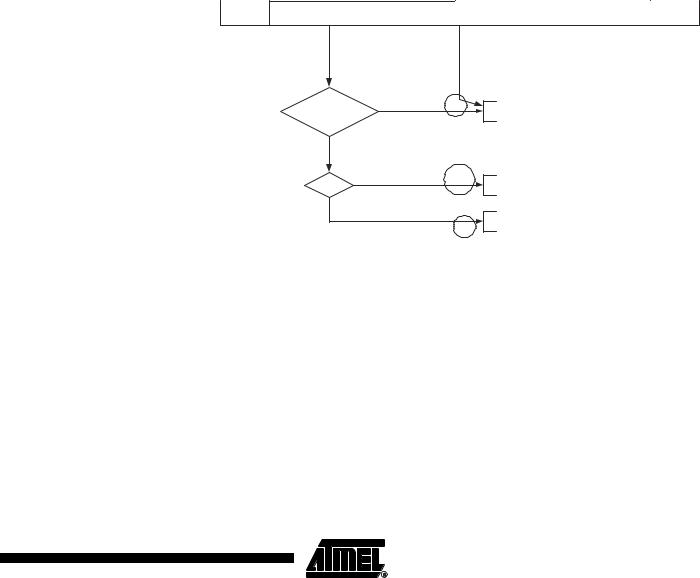
Figure 85. Formats and States in the Slave Transmitter Mode
|
|
Reception of the own |
S |
SLA |
R |
|
A |
|
DATA |
A |
|
DATA |
|
|
|
|
|
|
P or S |
|
|
|
|||
|
|
slave address and one or |
|
|
|
|
|
A |
|
|
|
|
|
||||||||||||
|
|
more data bytes |
|
|
|
|
|
|
|
|
|
|
|
|
|
|
|
|
|
|
|
|
|
|
|
|
|
|
|
|
|
|
|
|
|
|
|
|
|
|
|
|
|
|
|
|
|
|
|
|
|
|
|
|
|
|
|
|
|
$A8 |
|
|
$B8 |
|
|
$C0 |
|
|
|
|
|||||||
|
|
Arbitration lost as master |
|
|
|
|
|
|
|
|
|
|
|
|
|
|
|
|
|
|
|
|
|
|
|
|
|
|
|
|
|
|
|
|
|
|
|
|
|
|
|
|
|
|
|
|
|
|
|
||
|
|
|
|
|
|
A |
|
|
|
|
|
|
|
|
|
|
|
|
|
|
|
|
|||
|
|
and addressed as slave |
|
|
|
|
|
|
|
|
|
|
|
|
|
|
|
|
|
|
|
|
|||
|
|
|
|
|
|
|
|
|
|
|
|
|
|
|
|
|
|
|
|
|
|
|
|
|
|
|
|
|
|
|
|
|
|
|
|
|
|
|
|
|
|
|
|
|
|
|
|
|
|
|
|
|
|
|
|
|
|
|
|
$B0 |
|
|
|
|
|
|
|
|
|
|
|
|
|
|
|
|
|
|
|
Last data byte transmitted. |
|
|
|
|
|
|
|
|
|
|
|
|
|
|
|
|
|
|
|
|
|
|
|
|
|
|
|
|
|
|
|
|
|
|
|
|
|
|
|
|
|
|
|
|
|
|
|
||
|
|
|
|
|
|
|
|
|
|
|
|
|
|
|
|
A |
|
All 1's |
P or S |
|
|||||
|
|
Switched to not addressed |
|
|
|
|
|
|
|
|
|
|
|
|
|
|
|
|
|||||||
|
|
slave (TWEA = '0') |
|
|
|
|
|
|
|
|
|
|
|
|
|
|
|
|
|
|
|
|
|
|
|
|
|
|
|
|
|
|
|
|
|
|
|
|
|
|
|
|
|
|
|
|
|
|
|
|
|
|
|
|
|
|
|
|
|
|
|
|
|
|
|
|
|
|
$C8 |
|
|
|
|
||||
|
|
|
|
|
|
|
|
|
|
|
|
|
|
|
|
|
|
|
|
|
|
|
|||
|
|
|
|
|
|
|
|
|
|
|
Any number of data bytes |
|
|
|
|
|
|
|
|
|
|
|
|||
|
|
|
From master to slave |
|
DATA |
|
|
A |
|
|
|
|
|
|
|
|
|
|
|
||||||
|
|
|
|
|
|
and their associated acknowledge bits |
|
|
|
|
|
|
|
|
|
||||||||||
|
|
|
From slave to master |
|
|
|
|
n |
|
This number (contained in TWSR) corresponds |
|
|
|
|
|||||||||||
|
|
|
|
|
|
|
|
|
|
|
|
||||||||||||||
|
|
|
|
|
|
|
|
|
|
to a defined state of the Two-Wire Serial Bus. The |
|
|
|
|
|||||||||||
|
|
|
|
|
|
|
|
|
|
|
|
|
|
||||||||||||
|
|
|
|
|
|
|
|
|
|
|
prescaler bits are zero or masked to zero |
|
|
|
|
||||||||||
Miscellaneous States |
There are two status codes that do not correspond to a defined TWI state, see Table 70. |
||||||||||||||||||||||||
Status 0xF8 indicates that no relevant information is available because the TWINT Flag is not set. This occurs between other states, and when the TWI is not involved in a serial transfer.
Status 0x00 indicates that a bus error has occurred during a Two-wire Serial Bus transfer. A bus error occurs when a START or STOP condition occurs at an illegal position in the format frame. Examples of such illegal positions are during the serial transfer of an address byte, a data byte, or an acknowledge bit. When a bus error occurs, TWINT is set. To recover from a bus error, the TWSTO Flag must set and TWINT must be cleared by writing a logic one to it. This causes the TWI to enter the not addressed Slave mode and to clear the TWSTO Flag (no other bits in TWCR are affected). The SDA and SCL lines are released, and no STOP condition is transmitted.
Table 70. |
Miscellaneous States |
|
|
|
|
|
|
||
Status Code |
|
|
|
Application Software Response |
|
|
|||
(TWSR) |
|
Status of the Two-wire Serial |
|
|
To TWCR |
|
|
||
Prescaler Bits |
|
Bus and Two-wire |
Serial Inter- |
|
|
|
|
||
|
To/from TWDR |
STA |
STO |
TWINT |
TWEA |
|
|||
are 0 |
|
face Hardware |
|
Next Action Taken by TWI Hardware |
|||||
|
|
|
|||||||
|
|
|
|
|
|
|
|||
0xF8 |
|
No relevant state |
information |
No TWDR action |
|
No TWCR action |
|
Wait or proceed current transfer |
|
|
|
available; TWINT = “0” |
|
|
|
|
|
|
|
0x00 |
|
Bus error due to an illegal |
No TWDR action |
0 |
1 |
1 |
X |
Only the internal hardware is affected, no STOP condi- |
|
|
|
START or STOP condition |
|
|
|
|
|
tion is sent on the bus. In all cases, the bus is released |
|
|
|
|
|
|
|
|
|
|
and TWSTO is cleared. |
187
2486M–AVR–12/03
 ATmega8(L)