

14 - 134 FUEL SYSTEMS |
|
Ä |
|
Fig. 16 Servicing Fuel Injector
(2)Being careful not to damage O-ring, install injector nozzle end into fuel rail receiver cap (Fig. 16).
(3)Install injector clip by sliding open end into top slot of the injector. The edge of the receiver cup will slide into the side slots of clip (Fig. 15).
(4)Repeat steps for remaining injectors.
(5)Install fuel rail assembly. Refer to Fuel Rail Assembly Installation in this section.
(6)Connect electrical connectors to injectors in correct order.
(7)Connect negative battery cable.
CAUTION: When using the ASD Fuel System Test, the Auto Shutdown (ASD) Relay remains energized for either 7 minutes, until the test is stopped, or until the ignition switch is turned to the Off position.
(8) With the ignition key in ON position, access the DRB II ASD Fuel System Test to pressurize the fuel system. Check for leaks.
MANIFOLD ABSOLUTE PRESSURE (MAP) SENSOR
(1)Remove vacuum hose and mounting screws from manifold absolute pressure (MAP) sensor (Fig. 17).
(2)Disconnect electrical connector from sensor. Remove sensor.
(3)Reverse the above procedure for installation.
CANISTER PURGE SOLENOID SERVICE
(1)Remove vacuum hose and electrical connector from solenoid (Fig. 18).
(2)Depress tab on top of solenoid and slide the solenoid downward out of mounting bracket.
(3)Reverse above procedure to install.
ENGINE CONTROLLER
(1)Remove air cleaner duct from engine controller.
(2)Disconnect negative cable from battery. Disconnect positive cable from battery.
(3)Remove battery holddown. Remove battery.
Fig. 17 Manifold Absolute Pressure Sensor
Fig. 18 Canister Purge Solenoid
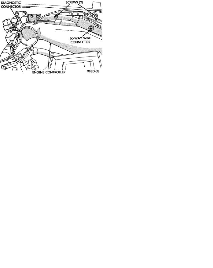
(4)Remove engine controller mounting screws (Fig. 19, Fig. 20 or Fig. 21).
(5)Remove the electrical connector from engine controller. Remove engine controller.
(6)Reverse the above procedure for installation.
Fig. 19 Engine ControllerÐAA Body

Ä
Fig. 20 Engine ControllerÐAC Body
Fig. 21 Engine ControllerÐAG and AJ Bodies
HEATED OXYGEN SENSOR (O2 SENSOR)
The oxygen sensor is installed in the exhaust manifold (Fig. 22).
CAUTION: Do not pull on the oxygen sensor wires when disconnecting the electrical connector.
FUEL SYSTEMS 14 - 135
Fig. 22 Heated Oxygen Sensor
WARNING: THE EXHAUST MANIFOLD MAY BE EXTREMELY HOT. USE CARE WHEN SERVICING THE OXYGEN SENSOR.
(1)Disconnect oxygen sensor electrical connector.
(2)Remove sensor using Tool C-4907 (Fig. 23).
Fig. 23 Oxygen Sensor Socket
When the sensor is removed, the exhaust manifold threads must be cleaned with an 18 mm X 1.5 + 6E tap. If using original sensor, coat the threads with Loctite 771-64 anti-seize compound or equivalent. New sensors are packaged with compound on the threads and do not require additional compound. The sensor must be tightened to 27 NIm (20 ft. lbs.) torque.