


Ä |
|
FUEL SYSTEMS 14 - 117 |
|
3.0L MULTI-POINT FUEL INJECTIONÐGENERAL DIAGNOSIS
INDEX
|
page |
60-Way Engine Controller Wiring Connector |
. . . . 127 |
Circuit Actuation Test Mode . . . . . . . . . . . . |
. . . . 125 |
Fault Code Description . . . . . . . . . . . . . . . . . |
. . . 122 |
Fuel System Diagram . . . . . . . . . . . . . . . . . . |
. . . 117 |
On Board Diagnostics . . . . . . . . . . . . . . . . . |
. . . 121 |
FUEL SYSTEM DIAGRAM
The 3.0L MPI system is managed by the engine controller. The controller receives inputs from various switches and sensors (Fig. 1). Based on these inputs, the engine controller adjusts ignition timing and idle speed through various output devices. Refer to the Multi-Point Fuel InjectionÐ3.0L Engine section of this group for system and component descriptions.
VISUAL INSPECTION
Perform a visual inspection for loose, disconnected, or misrouted wires and hoses before diagnosing or servicing the fuel injection system. A visual check saves unnecessary test and diagnostic time. A thorough visual inspection includes the following checks:
|
page |
State Display Test Mode . . . . . . . . . . . . . . . . . . |
. 125 |
System Tests . . . . . . . . . . . . . . . . . . . . . . . . . . . |
124 |
Throttle Body Minimum Air Flow Check Procedure |
. 125 |
Visual Inspection . . . . . . . . . . . . . . . . . . . . . . . . |
117 |
(1)Check for correct spark plug cable routing. Ensure the cables are completely connected to the spark plugs and distributor.
(2)Check ignition coil electrical connections (Fig. 2).
(3)Verify the electrical connector is attached to the Purge Solenoid (Fig. 3).
(4)Verify vacuum connection at Purge Solenoid is secure and not leaking (Fig. 3).
(5)Verify the electrical connector is attached to the MAP sensor (Fig. 4).
(6)Check MAP sensor hose at MAP Sensor Assembly (Fig. 4), and at Vacuum Connection at Intake Plenum Fitting.
(7)Check alternator wiring connections. Ensure the accessory drive belt has proper tension.
Fig. 1 Multi-Point Fuel Injection Components

14 - 118 FUEL SYSTEMS
Fig. 2 Ignition Coil Electrical Connection
Fig. 3 Electrical Connector Canister Purge Solenoid
Fig. 4 Map Sensor Electrical and Vacuum Connec-
tions
(8)Verify hoses are securely attached to the vapor canister (Fig. 5).
(9)Verify the engine ground strap is attached at the engine and dash panel (Fig. 6).
Ä
Fig. 5 Vapor Canister
Fig. 6 Oxygen Sensor Connector
(10)Ensure the heated oxygen sensor connector is connected to the harness connector (Fig. 6).
(11)Verify the distributor connector is connected to the harness connector (Fig. 7).
Fig. 7 Distributor Connector
Ä |
|
FUEL SYSTEMS 14 - 119 |
|
(12)Verify the coolant temperature sensor connector is connected to the harness connector (Fig. 8).
(13)Check vacuum hose connection at fuel pressure regulator and intake plenum connector (Fig. 8).
Fig. 10 Throttle Body Electrical and Vacuum Hose
Connections
Fig. 8 Coolant Temperature Sensor and Vacuum
Connections
(14)Ensure the harness connector is securely attached to each fuel injector.
(15)Check the oil pressure sending unit electrical connection (Fig. 9).
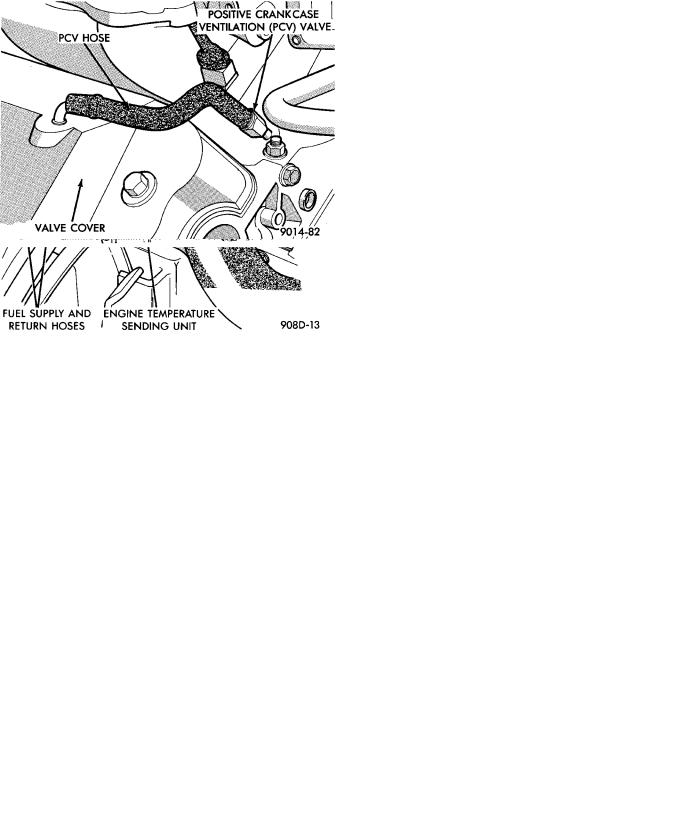
Fig. 11 Positive Crankcase Ventilation (PCV) System
Fig. 9 Oil Pressure Sending Unit Electrical Connec-
tion
(16)Check hose connections at throttle body (Fig.
10).
(17)Check throttle body electrical connections (Fig.
10).
(18)Check PCV hose connections (Fig. 11).
Fig. 12 EGR System Vacuum Hose Connections
(19)If equipped, check EGR system vacuum hose connections (Fig. 12).
(20)If equipped, check EGR tube to intake plenum connections (Fig. 12).

14 - 120 FUEL SYSTEMS |
|
Ä |
|
(21)Inspect the electronic EGR transducer solenoid electrical connector.
(22)Ensure the vacuum connections at the electronic EGR transducer is secure and not leaking.
(23)Check Power Brake Booster and Speed Connections (Figs. 13 and 14).
Fig. 15 Automatic Transmission Electrical Connec-
tions
Fig. 13 Power Brake Booster and Speed Control
Vacuum Hose Connections (Without Anti-lock
Brakes)
Fig. 14 Speed Control Vacuum Hose Connection
(With Anti-lock Brakes)
(24)Inspect engine harness to main harness connections.
(25)Check all automatic transmission electrical connections (Fig. 15).
(26)Check the distance sensor electrical connection (Fig. 16).
(27)Inspect the engine controller 60-way electrical connector for damage or spread terminals. Verify the 60-way connector is fully inserted into the socket of the engine controller. Ensure wires are not stretched or pulled out of the connector (Figs. 17, 18, and 19).
Fig. 16 Distance Sensor Electrical Connector
Fig. 17 Engine ControllerÐAA Body
(28)Check the air conditioning, starter, ASD, fuel pump and radiator fan relay connections (Figs. 20, 21, and 22).
(29)Check battery cable connections.
(30)Check hose and electrical connections at fuel pump. Ensure connector is making contact with terminals on pump.