

Ä
Fig. 17 Fuel Injector Location
ground path for the injectors. By switching the ground path on and off, the controller adjusts injector pulse width. Pulse width is the amount of time the injector is energized. The controller adjusts injector pulse width based on inputs it receives.
IGNITION COILÐENGINE CONTROLLER OUTPUT
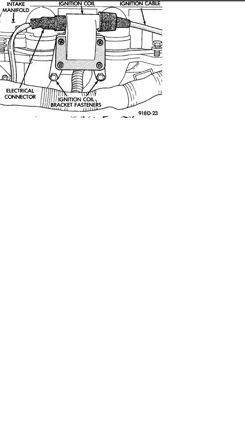
The auto shutdown (ASD) relay provides battery voltage to the ignition coil. The engine controller provides a ground contact (circuit) for energizing coil. When the controller breaks the contact, the energy in the coil primary transfers to the secondary causing the spark. The engine controller will de-energize the ASD relay if it does not receive an input from the distributor pick-up. Refer to Auto Shutdown (ASD) Relay/Fuel Pump RelayÐEngine Controller Output in this section for relay operation.
The ignition coil is mounted on a bracket next to the air cleaner (Fig. 18).
Fig. 18 Ignition Coil
FUEL SYSTEMS 14 - 113
PART THROTTLE UNLOCK SOLENOIDÐENGINE CONTROLLER OUTPUT
Three-speed automatic transaxles use a part throttle unlock solenoid. The engine controller controls the lock-up of the torque convertor through the part throttle unlock solenoid. The transmission is locked up only in direct drive mode. Refer to Group 21 for transmission information.
RADIATOR FAN RELAYÐENGINE CONTROLLER OUTPUT
The radiator fan is energized by the engine controller through the radiator fan relay. The radiator fan relay is located on the drivers side fender well near to the engine controller. The controller grounds the relay when engine coolant reaches a predetermined temperature or the air conditioning system turns on.
On AA body vehicles, the relay is located next to the drivers side strut tower (Fig. 13).
On AC, AG and AJ body vehicles, the relay is located in the power distribution center (Fig. 12 or Fig. 14).
SPEED CONTROL SOLENOIDSÐENGINE CONTROLLER OUTPUT
The speed control vacuum and vent solenoids are operated by the engine controller. When the engine controller supplies a ground to the vacuum solenoid, the speed control system opens the throttle plate. When the controller supplies a ground to the vent solenoid, the throttle blade closes. The engine controller balances the two solenoids to maintain the set speed. Refer to Group 8H for speed control information.
TACHOMETERÐENGINE CONTROLLER OUTPUT
The engine controller supplies engine RPM to the instrument panel tachometer through the CCD Bus. The CCD Bus is a communications port. Various modules use the CCD Bus to exchange information. Refer to Group 8E for more information.
MODES OF OPERATION
As input signals to the engine controller change, the engine controller adjusts its response to the output devices. For example, the engine controller must calculate a different injector pulse width and ignition timing for idle than for wide open throttle (WOT). There are several different modes of operation that determine how the engine controller responds to the various input signals.
There are two different areas of operation, OPEN LOOP and CLOSED LOOP.
During OPEN LOOP modes the engine controller receives input signals and responds according to preset engine controller programming. Input from the oxygen (O2) sensor is not monitored during OPEN LOOP modes.

14 - 114 FUEL SYSTEMS
During CLOSED LOOP modes the engine controller does monitor the oxygen (O2) sensor input. This input indicates to the controller if the injector pulse width results in an air-fuel ratio of 14.7 parts air to 1 part fuel. By monitoring the exhaust oxygen content through the O2 sensor, the engine controller can fine tune the injector pulse width. Fine tuning injector pulse width allows the engine controller to achieve optimum fuel economy combined with low emissions.
The 3.0L sequential MPI system has the following modes of operation:
²Ignition switch ONÐZero-RPM
²Engine start-up
²Engine warm-up
²Cruise (Idle)
²Acceleration
²Deceleration
²Wide Open Throttle
²Ignition switch OFF
The engine start-up (crank), engine warm-up, and wide open throttle modes are OPEN LOOP modes. The acceleration, deceleration, and cruise modes, with the engine at operating temperature are CLOSED LOOP modes (under most operating conditions).
IGNITION SWITCH ON (ZERO RPM) MODE
When the multi-point fuel injection system is activated by the ignition switch, the following actions occur:
²The engine controller determines atmospheric air pressure from the MAP sensor input to determine basic fuel strategy.
²The engine controller monitors the coolant temperature sensor and throttle position sensor input. The engine controller modifies fuel strategy based on these inputs.
When the key is in the ON position and the engine is not running (zero rpm), the auto shutdown (ASD) relay and fuel pump relay are not energized. Therefore battery voltage is not supplied to the fuel pump, ignition coil, fuel injectors or oxygen sensor heating element.
ENGINE START-UP MODE
This is an OPEN LOOP mode. The following actions occur when the starter motor is engaged.
If the engine controller receives a distributor signal, it energizes the auto shutdown (ASD) relay and fuel pump relay. These relays supply battery voltage to the fuel pump, fuel injectors, ignition coil, and oxygen sensor heating element. If the engine controller does not receive a distributor input, the ASD relay and fuel pump relay will be de-energized after approximately one second.
Ä
The engine controller energizes all six injectors until it determines crankshaft position from the distributor pick-up signals. The controller determines crankshaft position within 2 engine revolutions.
After determining crankshaft position, the engine controller begins energizing the injectors in sequence. The controller adjusts injector pulse width and controls injector synchronization by turning the individual ground paths to the injectors On and Off.
When the engine idles within 664 RPM of its target RPM, the controller compares current MAP sensor value with the atmospheric pressure value received during the Ignition Switch On (zero RPM) mode. If the controller does not detect a minimum difference between the two values, it sets a MAP fault into memory.
Once the ASD and fuel pump relays have been energized, the engine controller:
²determines injector pulse width based on coolant temperature, manifold absolute pressure (MAP) and the number of engine revolutions since cranking was initiated.
²monitors the coolant temperature sensor, distributor pick-up, MAP sensor, and throttle position sensor to determine correct ignition timing.
ENGINE WARM-UP MODE
This is a OPEN LOOP mode. The following inputs are received by the engine controller:
²coolant temperature
²crankshaft position (distributor pick-up)
²manifold absolute pressure (MAP)
²engine speed (distributor pick-up)
²throttle position
²A/C switch
²battery voltage
The controller adjusts injector pulse width and controls injector synchronization by turning the individual ground paths to the injectors On and Off.
The engine controller adjusts engine idle speed by regulating the automatic idle speed motor and ignition timing.
CRUISE OR IDLE MODE
When the engine is at operating temperature this is a CLOSED LOOP mode. During cruising speed the following inputs are received by the engine controller:
²coolant temperature
²crankshaft position (distributor pick-up)
²manifold absolute pressure
²engine speed (distributor pick-up)
²throttle position
²exhaust gas oxygen content
²A/C control positions
²battery voltage
Ä |
|
FUEL SYSTEMS 14 - 115 |
|
The controller adjusts injector pulse width and controls injector synchronization by turning the individual ground paths to the injectors On and Off.
The engine controller adjusts engine idle speed and ignition timing. The engine controller controls the air/fuel ratio according to the oxygen content in the exhaust gas.
ACCELERATION MODE
This is a CLOSED LOOP mode. The engine controller recognizes an abrupt increase in throttle position or MAP pressure as a demand for increased engine output and vehicle acceleration. The engine controller increases injector pulse width in response to increased fuel demand.
DECELERATION MODE
This is a CLOSED LOOP mode. During deceleration the following inputs are received by the engine controller:
²coolant temperature
²crankshaft position (distributor pick-up)
²manifold absolute pressure
²engine speed (distributor pick-up)
²throttle position
²exhaust gas oxygen content
²A/C control positions
²battery voltage
The engine controller may receive a closed throttle input from the throttle position sensor (TPS) when it senses an abrupt decrease in manifold pressure. This indicates a hard deceleration. The engine controller
may reduce injector firing to once per engine revolution. This helps maintain better control of the air-fuel mixture.
During a deceleration condition, the engine controller grounds the exhaust gas recirculation (EGR) solenoid. When the controller grounds the solenoid, preventing EGR.
WIDE OPEN THROTTLE MODE
This is an OPEN LOOP mode. During wide-open- throttle operation, the following inputs are received by the engine controller:
²coolant temperature
²crankshaft position (distributor pick-up)
²manifold absolute pressure
²engine speed (distributor pick-up)
²throttle position
When the engine controller senses wide open throttle condition through the throttle position sensor (TPS) it will:
²Provide a ground for the electrical EGR transducer (EET) solenoid. When the controller grounds the solenoid, the EGR system stops operating.
²De-energize the air conditioning relay. This disables the air conditioning system.
The exhaust gas oxygen content input is not accepted by the engine controller during wide open throttle operation. The engine controller will adjust injector pulse width to supply a predetermined amount of additional fuel.
IGNITION SWITCH OFF MODE
When the ignition switch is turned to the OFF position, the following occurs:
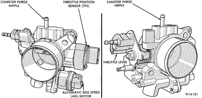
Fig. 19 Throttle Body

14 - 116 FUEL SYSTEMS
²All outputs are turned off.
²No inputs are monitored.
²The engine controller shuts down.
THROTTLE BODY
The throttle body assembly (Fig. 19) is located at the left end of the air intake plenum. The throttle body houses the throttle position sensor and the automatic idle speed motor. Air flow through the throttle body is controlled by a cable operated throttle blade located in the base of the throttle body.
FUEL SUPPLY CIRCUIT
Fuel is supplied to the fuel rail by an electric pump mounted in the fuel tank. The pump inlet is fitted with a strainer to prevent water and other contaminants from entering the fuel supply circuit.
Fuel pressure is controlled to a preset level above intake manifold pressure by a pressure regulator. The pressure regulator is mounted on the fuel rail. The regulator uses intake manifold pressure as a reference.
Ä
FUEL PRESSURE REGULATOR
The pressure regulator is a mechanical device located on the fuel rail, downstream of the fuel injectors (Fig. 20). The regulator maintains a constant 328 kPa (47.6 psi) across the fuel injector tip.
The regulator contains a spring loaded rubber diaphragm that covers the fuel return port. When the fuel pump is operating, fuel flows past the injectors into the regulator. Fuel is restricted from flowing any further by the blocked return port. When fuel pressure reaches 328 kPa (47.6 psi) it pushes on the diaphragm, compresses the spring, and uncovers the fuel return port. The diaphragm and spring constantly move from an open to closed position to keep the fuel pressure constant.
Fig. 20 Fuel Pressure Regulator