

Ä |
|
FUEL SYSTEMS 14 - 105 |
|
3.0L MULTI-POINT FUEL INJECTIONÐSYSTEM OPERATION
INDEX
|
page |
Air Conditioning (A/C) Clutch Relay (AA, AG, AJ |
|
Body)ÐEngine Controller Output . . . . . . . . . . . |
110 |
Air Conditioning (A/C) Clutch Relay |
|
(AC Body)ÐEngine Controller Output . . . . . . . . |
110 |
Air Conditioning Switch Sense (AA, AG, AJ |
|
Body)ÐEngine Controller Input . . . . . . . . . . . . |
107 |
Air Conditioning Switch Sense (AC Body)ÐEngine |
|
Controller Input . . . . . . . . . . . . . . . . . . . . . . . . |
107 |
Alternator FieldÐEngine Controller Output . . . . . . |
111 |
Auto Shutdown (ASD) Relay and Fuel Pump |
|
RelayÐEngine Controller Output . . . . . . . . . . . |
111 |
Automatic Idle Speed (AIS) MotorÐEngine |
|
Controller Output . . . . . . . . . . . . . . . . . . . . . . . |
111 |
Battery VoltageÐEngine Controller Input . . . . . . . |
107 |
Brake SwitchÐEngine Controller Input . . . . . . . . |
107 |
Canister Purge SolenoidÐEngine Controller |
|
Output . . . . . . . . . . . . . . . . . . . . . . . . . . . . . . . |
111 |
CCD Bus . . . . . . . . . . . . . . . . . . . . . . . . . . . . . . |
105 |
Check Engine LampÐEngine Controller Output . . |
112 |
Coolant Temperature SensorÐEngine Controller |
|
Input . . . . . . . . . . . . . . . . . . . . . . . . . . . . . . . . |
107 |
Diagnostic ConnectorÐEngine Controller Output . |
112 |
Distributor Pick-UpÐEngine Controller Input . . . . |
107 |
Electronic Automatic Transaxle ControllerÐEngine |
|
Controller Output . . . . . . . . . . . . . . . . . . . . . . . |
112 |
GENERAL INFORMATION |
|
The 3.0L engine uses a sequential Multi-Point Elec- |
|
tronic Fuel Injection system (Fig. 1). The MPI system |
|
is computer regulated and provides precise air/fuel |
|
ratios for all driving conditions. |
|
The MPI system is operated by the Single Board |
|
Engine Controller II (SBEC II), referred to in this |
|
manual as the engine controller. |
|
The engine controller regulates ignition timing, air- |
|
fuel ratio, emission control devices, cooling fan, charg- |
|
ing system, idle speed and speed control. Various |
|
sensors provide the inputs necessary for the engine |
|
controller to correctly operate these systems. In addi- |
|
tion to the sensors, various switches also provide |
|
inputs to the engine controller. |
|
All inputs to the engine controller are converted |
|
into signals. The engine controller can adapt its pro- |
|
gramming to meet changing operating conditions. |
|
Fuel is injected into the intake port above the intake |
|
valve in precise metered amounts through electrically |
|
operated injectors. The engine controller fires the injec- |
|
tors in a specific sequence. The controller maintains an |
|
air fuel ratio of 14.7 parts air to 1 part fuel by constantly |
|
adjusting injector pulse width. Injector pulse width is |
|
the length of time the injector is energized. |
|
The engine controller adjusts injector pulse width |
|
by opening and closing the ground path to the injec- |
|
tor. Engine RPM (speed) and manifold absolute pres- |
|
|
page |
Engine Controller . . . . . . . . . . . . . . . . . . . . . . . |
. 105 |
Fuel InjectorsÐEngine Controller Output . . . . . . |
. 112 |
Fuel Pressure Regulator . . . . . . . . . . . . . . . . . . . |
116 |
Fuel Supply Circuit . . . . . . . . . . . . . . . . . . . . . . . |
116 |
General Information . . . . . . . . . . . . . . . . . . . . . . |
105 |
Ignition CoilÐEngine Controller Output . . . . . . . . |
113 |
Manifold Absolute Pressure (MAP) SensorÐEngine |
|
Controller Input . . . . . . . . . . . . . . . . . . . . . . . . |
108 |
Modes of Operation . . . . . . . . . . . . . . . . . . . . . . |
113 |
Oxygen Sensor (O2 Sensor)ÐEngine Controller |
|
Input . . . . . . . . . . . . . . . . . . . . . . . . . . . . . . . . |
108 |
Part Throttle Unlock SolenoidÐEngine Controller |
|
Output . . . . . . . . . . . . . . . . . . . . . . . . . . . . . . |
113 |
Radiator Fan RelayÐEngine Controller Output . . |
113 |
Speed Control SolenoidsÐEngine Controller |
|
Output . . . . . . . . . . . . . . . . . . . . . . . . . . . . . . |
113 |
Speed ControlÐEngine Controller Input . . . . . . . |
109 |
TachometerÐEngine Controller Output . . . . . . . . |
113 |
Throttle Body . . . . . . . . . . . . . . . . . . . . . . . . . . . |
116 |
Throttle Position Sensor (TPS)ÐEngine Controller |
|
Input . . . . . . . . . . . . . . . . . . . . . . . . . . . . . . . . |
109 |
Transmission Park/Neutral SwitchÐEngine |
|
Controller Input . . . . . . . . . . . . . . . . . . . . . . . . |
109 |
Vehicle Distance (Speed) SensorÐEngine |
|
Controller Input . . . . . . . . . . . . . . . . . . . . . . . . |
110 |
sure (air density) are the primary inputs that determine injector pulse width.
SYSTEM DIAGNOSIS
The engine controller tests many of its own input and output circuits. If a fault is found in a major system, the information is stored in memory. Technicians can display fault information through the instrument panel Check Engine lamp or by connecting the Diagnostic Readout Box II (DRB II). For fault code information, refer to On Board Diagnostics in 3.0 Multi-Point Fuel InjectionÐGeneral Diagnosis section of this group.
CCD BUS
Various controllers and modules exchange information through a communications port called the CCD Bus. The engine controller transmits the check engine lamp On/Off signal, engine RPM and vehicle load data on the CCD Bus.
ENGINE CONTROLLER
The engine controller is a digital computer containing a microprocessor (Fig. 2). The controller receives input signals from various switches and sensors that are referred to as Engine Controller Inputs. Based on these inputs, the controller adjusts various engine and vehicle operations through devices referred to as Engine Controller Outputs.

14 - 106 FUEL SYSTEMS |
|
Ä |
|
Fig. 1 Multi-Point Fuel Injection Components
|
² Park/Neutral Switch (automatic transmission) |
|
² Vehicle Distance (Speed) Sensor |
|
Engine Controller Outputs: |
|
² Air Conditioning Clutch Relay |
|
² Alternator Field |
|
² Automatic Idle Speed (AIS) Motor |
|
² Auto Shutdown (ASD) and Fuel Pump Relays |
|
² Canister Purge Solenoid |
|
² Check Engine Lamp |
|
² Diagnostic Connector |
|
² Electric EGR Transducer (EET) |
|
² Fuel Injectors |
|
² Ignition Coil |
|
² Part Throttle Unlock (PTU) Solenoid |
|
² Radiator Fan Relay |
Fig. 2 Engine Controller |
² Speed Control Solenoids |
Engine Controller Inputs: |
² Tachometer Output |
Based on inputs it receives, the engine controller |
|
² Air Conditioning Controls |
adjusts fuel injector pulse width, idle speed, ignition |
² Battery Voltage |
spark advance, ignition coil dwell and canister purge |
² Brake Switch |
operation. The engine controller regulates the cooling |
² Coolant Temperature Sensor |
fan, air conditioning and speed control systems. The |
² Distributor Pick-up |
controller changes alternator charge rate by adjusting |
² Manifold Absolute Pressure (MAP) Sensor |
the alternator field. |
² Oxygen Sensor |
The engine controller adjusts injector pulse width |
² SCI Receive |
(air-fuel ratio) based on the following inputs. |
² Speed Control System Controls |
² battery voltage |
² Throttle Position Sensor |
² coolant temperature |

Ä
²exhaust gas content
²engine speed (distributor pick-up)
²manifold absolute pressure
²throttle position
The engine controller adjusts ignition timing based on the following inputs.
²coolant temperature
²engine speed (distributor pick-up)
²manifold absolute pressure
²throttle position
The Automatic Shut Down (ASD) and Fuel Pump relays are mounted externally, but turned on and off by the engine controller through the same circuit.
The distributor pick-up signal is sent to the engine controller. If the engine controller does not receive a distributor signal within approximately one second of engine cranking, the ASD relay and fuel pump relay are deactivated. When these relays are deactivated, power is shut off to the fuel injector, ignition coil, oxygen sensor heating element and fuel pump.
The engine controller contains a voltage converter that changes battery voltage to a regulated 9.0 volts. The 9.0 volts power the distributor pick-up and vehicle speed sensor. The controller also provides a 5.0 volts supply for the coolant temperature sensor, manifold absolute pressure sensor and throttle position sensor.
AIR CONDITIONING SWITCH SENSE (AA, AG, AJ BODY)ÐENGINE CONTROLLER INPUT
When the air conditioning or defrost switch is in the ON position and the low pressure and high pressure switches are closed, the controller receives an input for air conditioning. After receiving this input, the engine controller activates the A/C compressor clutch by grounding the A/C clutch relay. The engine controller also adjusts idle speed to a scheduled RPM to compensate for increased engine load.
AIR CONDITIONING SWITCH SENSE (AC
BODY)ÐENGINE CONTROLLER INPUT
When the air conditioning or defrost switch is in the ON position and the low pressure, high pressure and ambient temperature switches are closed, the controller receives an input for air conditioning. After receiving this input, the engine controller activates the A/C compressor clutch by grounding the A/C clutch relay. The engine controller also adjusts idle speed to a scheduled RPM to compensate for increased engine load.
BATTERY VOLTAGEÐENGINE CONTROLLER INPUT
The engine controller monitors the battery voltage input to determine fuel injector pulse width and alternator field control. If battery voltage is low, the engine controller will increase injector pulse width.
FUEL SYSTEMS 14 - 107
BRAKE SWITCHÐENGINE CONTROLLER INPUT
When the brake switch is activated, the engine controller receives an input indicating that the brakes are being applied. After receiving this input the engine controller maintains idle speed to a scheduled RPM through the automatic idle speed motor. The brake switch is mounted on the brake pedal support bracket.
COOLANT TEMPERATURE SENSORÐENGINE CONTROLLER INPUT
The coolant temperature sensor is a variable resistor with a range of -40° to 265°. The sensor is installed next to the thermostat housing.
The engine controller supplies 5.0 volts to the coolant temperature sensor. The sensor provides an input voltage to the engine controller (Fig. 3). As coolant temperature varies, the sensors resistance changes, resulting in a different input voltage to the engine controller.
The engine controller demands slightly richer airfuel mixtures and higher idle speeds until the engine reaches normal operating temperature.
This sensor is also used for cooling fan control.
Fig. 3 Coolant Temperature Sensor
DISTRIBUTOR PICK-UPÐENGINE CONTROLLER INPUT
The distributor pick-up provides two inputs to the engine controller. From one input the engine controller determines RPM (engine speed). From the other input it derives crankshaft position. The engine controller regulates injector synchronization and adjusts ignition timing and engine speed based on these inputs.
The distributor pick-up contains two signal generators. The pick-up unit consists of 2 light emitting diodes (LED), 2 photo diodes, and a separate timing disk. The timing disk contains two sets of slots. Each set of slots rotates between a light emitting diode and a photo diode (Fig. 4). The inner set contains 6

14 - 108 FUEL SYSTEMS |
|
Ä |
|
large slots, one for each cylinder. The outer set contains several smaller slots.
Fig. 4 Distributor Pick-up
The outer set of slots on the rotating disk represents 2 degrees of crankshaft rotation. Up to 1200 engine RPM, the controller uses the input from the outer set of slots to increase ignition timing accuracy.
The outer set of slots contains a 10 degree flat spot (Fig. 5). The flat spot tells the engine controller that the next piston at TDC will be number 6. The position of each piston is referenced by one of the six inner slots (Fig. 5).
As each slot on the timing disk passes between the diodes, the beam from the light emitting diode is interrupted. This creates an alternating voltage in each photo diode which is converted into on-off pulses. The pulses are the input to the engine controller.
During cranking, the controller cannot determine crankshaft position until the 10 degree flat spot on the outer set of slots passes through the optical unit. Once the flat spot is detected, the controller knows piston number 6 will be the next piston at TDC.
Since the disk rotates at half crankshaft speed, it may take 2 engine revolutions during cranking for the controller to determine the position of piston number 6. For this reason the engine controller will energize all six injectors at the same time until it senses the position of piston number 6.
MANIFOLD ABSOLUTE PRESSURE (MAP) SENSORÐENGINE CONTROLLER INPUT
The engine controller supplies 5 volts to the MAP sensor. The Map sensor converts intake manifold pressure into voltage. The engine controller monitors the MAP sensor output voltage. As vacuum increases, MAP sensor voltage decreases proportionately. Also, as vacuum decreases, MAP sensor voltage increases proportionately.
Fig. 5 Inner and Outer Slots of Rotating Disk
During cranking, before the engine starts running, the engine controller determines atmospheric air pressure from the MAP sensor voltage. While the engine operates, the controller determines intake manifold pressure from the MAP sensor voltage.
Based on MAP sensor voltage and inputs from other sensors, the engine controller adjusts spark advance and the air/fuel mixture.
The MAP sensor (Fig. 6) mounts on a bracket attached to the alternator bracket. The sensor is connected to the throttle body with a vacuum hose and to the engine controller electrically.
Fig. 6 Map Sensor
OXYGEN SENSOR (O2 SENSOR)ÐENGINE CONTROLLER INPUT
The O2 sensor is located in the exhaust manifold and provides an input voltage to the engine controller. The input tells the engine controller the oxygen content of the exhaust gas (Fig. 7). The engine controller uses this information to fine tune the air-fuel ratio by adjusting injector pulse width.

Ä
Fig. 7 Oxygen SensorÐ3.0L Engine
The O2 sensor produces voltages from 0 to 1 volt, depending upon the oxygen content of the exhaust gas. When a large amount of oxygen is present (caused by a lean air-fuel mixture), the sensor produces a low voltage. When there is a lesser amount present (rich air-fuel mixture) it produces a higher voltage. By monitoring the oxygen content and converting it to electrical voltage, the sensor acts as a rich-lean switch.
The oxygen sensor is equipped with a heating element that keeps the sensor at proper operating temperature during all operating modes. Maintaining correct sensor temperature at all times allows the system to enter into Closed Loop operation sooner. Also, it allow the system to remain in Closed Loop operation during periods of extended idle.
In Closed Loop operation the engine controller monitors the O2 sensor input (along with other inputs) and adjusts the injector pulse width accordingly. During Open Loop operation the engine controller ignores the O2 sensor input. The controller adjusts injector pulse width based on preprogrammed (fixed) values and from inputs of other sensors.
SPEED CONTROLÐENGINE CONTROLLER INPUT
The speed control system provides four separate voltages (inputs) to the engine controller. The voltages correspond to the On/Off, Set, and Resume.
The speed control ON voltage informs the engine controller that the speed control system has been activated. The speed control SET voltage informs the controller that a fixed vehicle speed has been selected. The speed control RESUME voltage indicates the previous fixed speed is requested. The speed control OFF voltage tells the controller that the speed control system has deactivated. Refer to Group 8H for further speed control information.
FUEL SYSTEMS 14 - 109
TRANSMISSION PARK/NEUTRAL SWITCHÐENGINE CONTROLLER INPUT
The park/neutral switch is located on the transmission housing (Fig. 8 or Fig. 9). It provides an input to the engine controller indicating whether the automatic transmission is in Park, Neutral, or a drive gear selection. This input is used to determine idle speed (varying with gear selection), fuel injector pulse width, and ignition timing advance. The park/neutral switch is sometimes referred to as the neutral safety switch.
Fig. 8 Park Neutral SwitchÐ3-Speed Automatic
Transaxle
Fig. 9 Park Neutral SwitchÐ4-Speed Electronic Au-
tomatic Transaxle
THROTTLE POSITION SENSOR (TPS)ÐENGINE CONTROLLER INPUT
The Throttle Position Sensor (TPS) is mounted on the throttle body and connected to the throttle blade shaft (Fig. 10). The TPS is a variable resistor that provides the engine controller with an input signal (voltage) representing throttle blade position. As the position of the throttle blade changes, the resistance of the TPS changes.
The engine controller supplies approximately 5 volts to the TPS. The TPS output voltage (input signal to the engine controller) represents throttle blade position. The TPS output voltage to the controller

14 - 110 FUEL SYSTEMS |
|
Ä |
|
Fig. 10 Throttle Position Sensor
varies from approximately 0.5 volt at minimum throttle opening (idle) to 3.5 volts at wide open throttle. The wide open throttle input is approximately 3 volts more than the minimum throttle opening value.
Along with inputs from other sensors, the engine controller uses the TPS input to determine current engine operating conditions. After determining the current operating conditions, the controller adjust fuel injector pulse width and ignition timing.
VEHICLE DISTANCE (SPEED) SENSORÐENGINE CONTROLLER INPUT
The distance sensor (Fig. 11) is located in the transmission extension housing. The sensor input is used by the engine controller to determine vehicle speed and distance traveled.
MAP value. Under idle conditions, the engine controller adjusts the AIS motor to maintain a desired engine speed.
AIR CONDITIONING (A/C) CLUTCH RELAY (AC BODY)ÐENGINE CONTROLLER OUTPUT
The engine controller operates the air conditioning clutch relay ground circuit. The ignition switch supplies battery power to the solenoid side of the relay. The A/C fan relay is operated independently of the engine controller by the Fan Cutout switch. When the A/C clutch relay energizes, battery voltage powers the A/C compressor clutch.
With the engine operating and the blower motor switch in the On position, the controller turns the A/C clutch on when the A/C switch closes. When the engine controller senses low idle speeds or wide open throttle through the throttle position sensor, it deenergizes the A/C clutch relay. The relay contacts open, preventing air conditioning clutch engagement.
On AC body vehicles, the relay is located in the power distribution center (Fig. 12).
Fig. 11 Vehicle Distance (Speed) SensorÐTypical
The distance sensor generates 8 pulses per sensor revolution. These signals, along with a closed throttle signal from the TPS, determine if a closed throttle deceleration or normal idle condition (vehicle stopped) exists. Under deceleration conditions, the engine controller adjusts the AIS motor to maintain a desired
Fig. 12 Relay Identification (AC Body)
AIR CONDITIONING (A/C) CLUTCH RELAY (AA, AG, AJ BODY)ÐENGINE CONTROLLER OUTPUT
The engine controller operates the air conditioning clutch relay ground circuit. The ignition switch supplies battery power to the solenoid side of the relay. When the A/C clutch relay energizes, battery voltage powers the A/C compressor clutch.
With the engine operating and the blower motor switch in the On position, the engine controller cycles the air conditioning clutch on and off when the A/C switch closes. When the engine controller senses low idle speeds or wide open throttle through the throttle position sensor, it de-energizes the A/C clutch relay. The relay contacts open, preventing air conditioning clutch engagement.
On AA body vehicles, the relay is located next to the drivers side strut tower (Fig. 13).
Ä
On AG and AJ body vehicles, the relay is located in the power distribution center (Fig. 14).
Fig. 13 Relay Identification (AA Body)
Fig. 14 Relay Identification (AG and AJ Body)
ALTERNATOR FIELDÐENGINE CONTROLLER OUTPUT
The engine controller regulates the charging system voltage within a range of 12.9 to 15.0 volts. Refer to Group 8A for charging system information.
AUTO SHUTDOWN (ASD) RELAY AND FUEL PUMP RELAYÐENGINE CONTROLLER OUTPUT
The engine controller operates the auto shutdown (ASD) relay and fuel pump relay through one ground path. The controller operates the relays by switching the ground path on and off. Both relays turn on and off at the same time.
FUEL SYSTEMS 14 - 111
The ASD relay connects battery voltage to the fuel injector and ignition coil. The fuel pump relay connects battery voltage to the fuel pump and oxygen sensor heating element.
The engine controller turns the ground path off when the ignition switch is in the Off position. Both relays are off. When the ignition switch is in the On or Crank position, the engine controller monitors the distributor pick-up signal to determine engine speed and ignition timing (coil dwell). If the engine controller does not receive a distributor signal when the ignition switch is in the Run position, it will deenergize both relays. When the relays are deenergized, battery voltage is not supplied to the fuel injector, ignition coil, fuel pump and oxygen sensor heating element.
On AA body vehicles, the relays are located next to the drivers side strut tower (Fig. 13).
On AC, AG and AJ body vehicles, the relays are located in the power distribution center (Fig. 12 or Fig. 14).
AUTOMATIC IDLE SPEED (AIS) MOTORÐENGINE CONTROLLER OUTPUT
The idle speed stepper motor is mounted on the throttle body and is controlled by the engine controller (Fig. 10). The engine controller adjusts engine idle speed through the AIS to compensate for engine load or ambient conditions.
The throttle body has an air bypass passage that provides air for the engine at idle (the throttle blade is closed). The AIS motor pintle protrudes into the air bypass passage and regulates air flow through it.
The engine controller adjusts engine idle speed by moving the AIS motor pintle in and out of the bypass passage. The adjustments are based on inputs the controller receives. The inputs are from the throttle position sensor, engine speed sensor (distributor pick-up coil), coolant temperature sensor, and various switch operations (brake, park/neutral, air conditioning). Deceleration die out is also prevented by increasing airflow when the throttle is closed quickly after a driving (speed) condition.
CANISTER PURGE SOLENOIDÐENGINE CONTROLLER OUTPUT
Vacuum for the evaporative canister is controlled by the Canister Purge Solenoid (Fig. 15). The solenoid is controlled by the engine controller.
The engine controller operates the solenoid by switching the ground circuit on and off. The controller turns the ground path on and off based on engine operating conditions. When grounded, the solenoid energizes and prevents vacuum from reaching the evaporative canister. When not energized the solenoid allows vacuum to flow to the canister.
14 - 112 FUEL SYSTEMS
Fig. 15 Canister Purge Solenoid
During warm-up and for a specified time period after hot starts the engine controller grounds the purge solenoid. Vacuum does not operate the evaporative canister valve.
The engine controller removes the ground to the solenoid when the engine reaches a specified temperature and the time delay interval has occurred. When the solenoid is de-energized, vacuum flows to the canister purge valve. Vapors are purged from the canister and flow to the throttle body.
The purge solenoid is energized during certain idle conditions to update the fuel delivery calibration.
CHECK ENGINE LAMPÐENGINE CONTROLLER OUTPUT
The check engine lamp comes on each time the ignition key is turned ON and stays on for 3 seconds as a bulb test. The check engine lamp warns the operator that the engine controller has entered a Limp-in mode. During Limp-in Mode, the controller attempts to keep the system operational. The check engine lamp signals the need for immediate service. In limp-in mode, the Engine controller compensates for the failure of certain components that send incorrect signals. The controller substitutes for the incorrect signals with inputs from other sensors.
Signals that can trigger the Check Engine Lamp.
²Coolant Temperature Sensor
²Manifold Absolute Pressure Sensor
²Throttle Position Sensor
²Battery Voltage Input
²An Emission Related System (California vehicles)
²Charging system
The Check Engine Lamp displays fault codes. Cycle the ignition switch on, off, on, off, on, within five seconds to display any fault codes stored in the controller. Refer to On Board Diagnostics in the General DiagnosisÐMulti-Point Fuel Injection, 3.0L Engine section of this Group for Fault Code Descriptions.
Ä
DIAGNOSTIC CONNECTORÐENGINE CONTROLLER OUTPUT
The diagnostic connector provides the technician with the means to connect the DRB II tester to diagnosis the vehicle.
ELECTRONIC AUTOMATIC TRANSAXLE CONTROLLERÐENGINE CONTROLLER OUTPUT
The engine controller supplies the following information to the electronic automatic transmission controller through the CCD Bus:
²battery temperature
²brake switch input
²coolant temperature
²manifold absolute pressure (MAP)
²speed control information
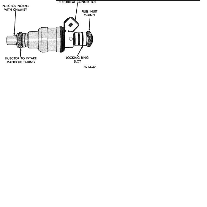
FUEL INJECTORSÐENGINE CONTROLLER OUTPUT
The fuel injectors are electrical solenoids (Fig. 16). The injector contains a pintle that closes off an orifice at the nozzle end. When electric current is supplied to the injector, the armature and pintle move a short distance against a spring, allowing fuel to flow out the orifice. Because the fuel is under high pressure, a fine spray is developed in the shape of a hollow cone. The spraying action atomizes the fuel, adding it to the air entering the combustion chamber.
Fig. 16 Fuel InjectorÐ3.0L Engine
The injectors are positioned in the intake manifold with the nozzle ends directly above the intake valve port (Fig. 16).
The fuel injectors are operated by the engine controller. They are energized in a sequential order during all engine operating conditions except start up. The controller initially energizes all injectors at the same time. Once the engine controller determines crankshaft position, it begins energizing the injectors in sequence.
Battery voltage is supplied to the injectors through the ASD relay. The engine controller provides the