

Ä
Vehicle Speed
Oxygen Sensor State
Baro Read Update
MAP Gauge Reading
Throttle Opening
Total Spark Advance
CIRCUIT ACTUATION TEST MODE
The purpose of the circuit actuation test mode is to check for the proper operation of output circuits or devices which the engine controller cannot internally recognize. The engine controller can attempt to activate these outputs and allow an observer to verify proper operation. Most of the tests available in this mode provide an audible or visual indication of device operation (click of relay contacts, spray fuel, etc.). With the exception of an intermittent condition, if a device functions properly during its test, assume the device, its associated wiring, and its driver circuit are in working order.
OBTAINING CIRCUIT ACTUATION TEST
Connect the DRB II tester to the vehicle and access the Actuators screen. The following is a list of the engine control system functions accessible through Actuators screens.
Stop All Tests
Ignition Coil #1
Ignition Coil #2
Fuel Injector #1
Fuel Injector #2
Fuel Injector #3
AIS Motor Open/Close Radiator Fan Relay A/C Clutch Relay Auto Shutdown Relay Purge Solenoid
S/C Serv Solenoids Alternator Field Tachometer Output Wastegate Solenoid Baro Read Solenoid All Solenoids/Relays ASD Fuel System Test Fuel Injector #4
THROTTLE BODY MINIMUM AIR FLOW CHECK PROCEDURE
(1)Warm the engine in neutral until the cooling fan has cycled on and off at least once.
(2)Shut off engine.
(3)Hook-up Tachometer.
FUEL SYSTEMS 14 - 97
(4)Disconnect the PCV valve hose from the nipple on the intake manifold.
(5)Attach air metering fitting, special tool 6457 (0.125 inch orifice), to the intake manifold PCV nipple.
(6)Disconnect 3/16 inch manifold vacuum purge line from the top of the throttle body. Cap the 3/16 inch throttle body nipple.
(7)Connect Diagnostic Readout Box II (DRB II).
(8)Restart engine. Allow engine to idle for at least one minute.
(9)Using the DRB II, access Min. Airflow Idle Spd. The following will then occur:
²AIS motor will fully close.
²Idle spark advance will become fixed.
²Engine RPM will be displayed on Diagnostic Readout Box II (DRB II).
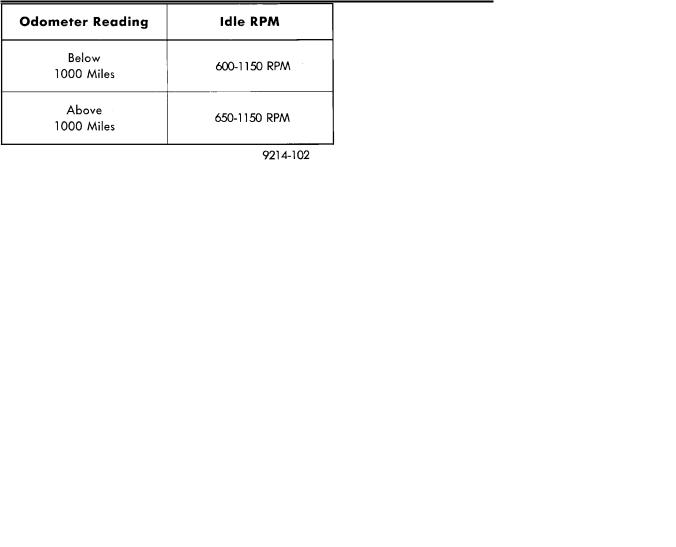
(10)Check idle RPM with tachometer, if idle RPM is within the below specification then the throttle body minimum airflow is set correctly.
IDLE SPECIFICATIONS
If the idle RPM is not within specification, replace the throttle body.
(11)Shut off engine.
(12)Remove air metering fitting 6457 from the intake manifold PCV nipple. Connect the PCV hose to the nipple.
(13)Remove DRB II.
(14)Disconnect tachometer.
(15)Reconnect purge line to throttle body.
IGNITION TIMING PROCEDURE
Ignition timing cannot be changed or set on the Turbo III engine. Refer to Group 8D for a description of the Direct Ignition System (DIS).
60-WAY ENGINE CONTROLLER WIRING CONNECTOR
Refer to the engine controller wiring connector diagram (Fig. 23) for information regarding wire colors and cavity numbers.

14 - 98 FUEL SYSTEMS |
|
Ä |
|
Fig. 23 60-Way Engine Controller Wiring Connector

Ä |
|
|
|
FUEL SYSTEMS 14 - 99 |
|
|
|
|
|||
|
2.2L TURBO III MULTI-POINT FUEL INJECTIONÐSERVICE PROCEDURES |
|
|||
|
|
INDEX |
|
||
|
|
page |
|
|
page |
Automatic Idle Speed (AIS) Motor . . . . . . . |
. . . . . 100 |
Heated Oxygen Sensor (O2 Sensor) . . . . . . . . . . |
104 |
||
Engine Controller Service . . . . . . . . . . . . . . |
. . . . 103 |
Manifold Absolute Pressure (MAP) Sensor Service |
. 103 |
||
Fuel Injector Rail Assembly . . . . . . . . . . . . |
. . . . 101 |
Throttle Body . . . . . . . . . . . . . . . . . . . . . . . . . . . |
99 |
||
Fuel Injectors . . . . . . . . . . . . . . . . . . . . . . . |
. . . . 102 |
Throttle Body Removal . . . . . . . . . . . . . . . . . . . . |
100 |
||
Fuel Pressure Regulator . . . . . . . . . . . . . . . |
. . . . 103 |
Throttle Position Sensor (TPS) . . . . . . . . . . . . . . |
100 |
||
Fuel System Pressure Release Procedure |
. . . . . 99 |
Wastegate and Canister Purge Solenoid Service |
. 103 |
||
THROTTLE BODY
When servicing throttle body components, always reassemble components with new O-rings and seals where applicable. (Fig. 1) Never use lubricants on O-rings or seals, damage may result. If assembly of component is difficult, use water to aid assembly. Use care when removing hoses to prevent damage to hose or hose nipple.
FUEL SYSTEM PRESSURE RELEASE PROCEDURE
CAUTION: The fuel system is under a constant pressure of approximately 380 kPa (55 psi). Before servicing the fuel pump, fuel lines, fuel filter, throttle body, or fuel injectors, the fuel system pressure must be released.
(1)Loosen fuel filler cap to release fuel tank pres-
sure.
(2)Disconnect injector wiring harness connector (Fig. 2).
Fig. 2 Injector Harness Connector
(3) Connect a jumper wire between terminal Number 1 of the injector harness and engine ground.
Fig. 1 Throttle Body