

14 - 76 FUEL SYSTEMS |
|
Ä |
|
2.2L TURBO III MULTI-POINT FUEL INJECTIONÐSYSTEM OPERATION
INDEX
page |
|
Air Conditioning Clutch RelayÐEngine Controller |
|
Output . . . . . . . . . . . . . . . . . . . . . . . . . . . . . . . |
82 |
Air Conditioning Switch SenseÐEngine Controller |
|
Input . . . . . . . . . . . . . . . . . . . . . . . . . . . . . . . . . |
78 |
Alternator FieldÐEngine Controller Output . . . . . . |
82 |
Auto Shutdown (ASD) Relay and Fuel Pump |
|
RelayÐEngine Controller Output . . . . . . . . . . . . |
82 |
Automatic Idle Speed (AIS) MotorÐEngine |
|
Controller Output . . . . . . . . . . . . . . . . . . . . . . . . |
83 |
Barometric Read SolenoidÐEngine Controller |
|
Output . . . . . . . . . . . . . . . . . . . . . . . . . . . . . . . |
83 |
Battery VoltageÐEngine Controller Input . . . . . . . . |
78 |
Brake SwitchÐEngine Controller Input . . . . . . . . . |
78 |
Camshaft SensorÐEngine Controller Input . . . . . . |
78 |
Canister Purge SolenoidÐEngine Controller |
|
Output . . . . . . . . . . . . . . . . . . . . . . . . . . . . . . . |
83 |
CCD Bus . . . . . . . . . . . . . . . . . . . . . . . . . . . . . . . |
76 |
Charge Temperature SensorÐEngine Controller |
|
Input . . . . . . . . . . . . . . . . . . . . . . . . . . . . . . . . . |
78 |
Check Engine LampÐEngine Controller Output . . |
83 |
Coolant Temperature SensorÐEngine Controller |
|
Input . . . . . . . . . . . . . . . . . . . . . . . . . . . . . . . . . |
79 |
Crankshaft SensorÐEngine Controller Input . . . . . |
79 |
Detonation Sensor (Knock Sensor)ÐEngine |
|
Controller Input . . . . . . . . . . . . . . . . . . . . . . . . . |
80 |
GENERAL INFORMATION |
|
The turbocharged multi-point electronic fuel injec- |
|
tion system combines an electronic fuel and spark |
|
advance control system with a turbocharged intake |
|
system (Fig. 1). The fuel injection system is controlled |
|
by the Single Board Engine Controller II (SBEC II), |
|
referred to in this manual as the engine control- |
|
ler. |
|
The engine controller regulates ignition timing, air- |
|
fuel ratio, emission control devices, cooling fan, charg- |
|
ing system, speed control, turbocharger wastegate |
|
and idle speed. The engine controller adapts its re- |
|
quirement to meet changing operating conditions. |
|
Various sensors provide the inputs necessary for the |
|
engine controller to correctly regulate fuel flow at the |
|
fuel injector. These include the manifold absolute |
|
pressure, throttle position, oxygen sensor, coolant |
|
temperature, detonation, and vehicle distance sen- |
|
sors. In addition to the sensors, the air conditioning |
|
clutch switch and various relays provide important |
|
information and system control. The outputs include |
|
the auto shutdown relay and fuel pump relay. |
|
All inputs to the engine controller are converted |
|
into signals. Based on these inputs the engine con- |
|
troller adjusts air-fuel ratio, ignition timing, turbo- |
|
charger wastegate and other controlled outputs. The |
|
engine controller adjusts the air-fuel ratio by chang- |
|
page |
|
Diagnostic ConnectorÐEngine Controller Output . . |
84 |
Engine Controller . . . . . . . . . . . . . . . . . . . . . . . . . |
76 |
Fuel InjectorÐEngine Controller Output . . . . . . . . |
84 |
Fuel Injectors and Fuel Rail Assembly . . . . . . . . . |
87 |
Fuel Pressure Regulator . . . . . . . . . . . . . . . . . . . . |
87 |
Fuel Supply Circuit . . . . . . . . . . . . . . . . . . . . . . . . |
86 |
General Information . . . . . . . . . . . . . . . . . . . . . . . |
76 |
Ignition CoilÐEngine Controller Output . . . . . . . . . |
84 |
Manifold Absolute Pressure (MAP) SensorÐEngine |
|
Controller Input . . . . . . . . . . . . . . . . . . . . . . . . . |
80 |
Modes of Operation . . . . . . . . . . . . . . . . . . . . . . . |
85 |
Oxygen Sensor (O2 Sensor)ÐEngine Controller |
|
Input . . . . . . . . . . . . . . . . . . . . . . . . . . . . . . . . . |
81 |
Radiator Fan RelayÐEngine Controller Output . . . |
84 |
Speed Control SolenoidsÐEngine Controller |
|
Output . . . . . . . . . . . . . . . . . . . . . . . . . . . . . . . |
85 |
Speed ControlÐEngine Controller Input . . . . . . . . |
81 |
TachometerÐEngine Controller Output . . . . . . . . . |
85 |
Throttle Body . . . . . . . . . . . . . . . . . . . . . . . . . . . . |
86 |
Throttle Position Sensor (TPS)ÐEngine Controller |
|
Input . . . . . . . . . . . . . . . . . . . . . . . . . . . . . . . . . |
81 |
Vehicle Distance (Speed) SensorÐEngine |
|
Controller Input . . . . . . . . . . . . . . . . . . . . . . . . . |
82 |
Wastegate Control SolenoidÐEngine Controller |
|
Output . . . . . . . . . . . . . . . . . . . . . . . . . . . . . . . |
85 |
ing injector pulse width. Injector pulse width is the |
|
time an injector is energized. |
|
SYSTEM DIAGNOSIS
The engine controller tests many of its own input and output circuits. If a fault is found in a major system, the information is stored in memory. Technicians can display fault information through the instrument panel Check Engine lamp. Also, the technician can read fault information by connecting the Diagnostic Readout Box II (DRB II) to the diagnostic connector. For fault code information, refer to On Board Diagnostics in 2.2L Turbo III Multi-Point Fuel InjectionÐGeneral Diagnosis section of this group.
CCD BUS
Various controllers and modules exchange information through a communications port called the CCD Bus. The engine controller transmits vehicle load data on the CCD Bus.
ENGINE CONTROLLER
The engine controller is a digital computer containing a microprocessor (Fig. 2). The controller receives input signals from various switches and sensors that are referred to as Engine Controller Inputs. Based on these inputs, the controller adjusts various engine and vehicle operations through devices that are referred to as Engine Controller Outputs.
Ä |
|
FUEL SYSTEMS 14 - 77 |
|
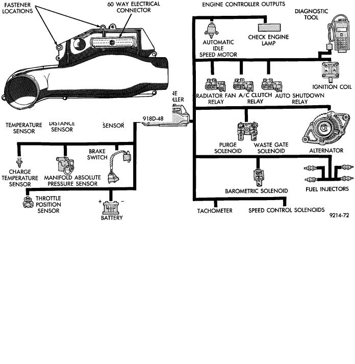
Fig. 1 Electronic Fuel Injection Components
Fig. 2 Engine Controller
Engine Controller Inputs:
²Air Conditioning Controls
²Battery Voltage
²Brake Switch
²Camshaft Sensor
²Crankshaft Sensor
²Charge Air Temperature Sensor
²Coolant Temperature Sensor
²Detonation Sensor
²Manifold Absolute Pressure (MAP) Sensor
²Oxygen Sensor
²SCI Receive
²Speed Control System Controls
²Throttle Position Sensor
²Vehicle Distance (Speed) Sensor
Engine Controller Outputs:
²Air Conditioning Clutch Relay
²Alternator Field
²Automatic Idle Speed (AIS) Motor
²Auto Shutdown (ASD) Relay
²Barometric Read Solenoid
²Canister Purge Solenoid
²Check Engine Lamp
²Diagnostic Connector
²Fuel Injectors
²Ignition Coil
²Radiator Fan Relay
²Speed Control Solenoids
²Tachometer Output
²Wastegate Solenoid
Based on inputs it receives, the engine controller adjusts fuel injector pulse width, idle speed, ignition spark advance, ignition coil dwell and canister purge operation. The engine controller regulates operation of the cooling fan, A/C and speed control systems. The controller changes alternator charge rate by adjusting the alternator field.

14 - 78 FUEL SYSTEMS
The engine controller adjusts injector pulse width (air-fuel ratio) based on the following inputs.
²battery voltage
²coolant temperature
²exhaust gas content
²engine speed (crankshaft sensor)
²manifold absolute pressure
²throttle position
The engine controller adjusts ignition timing based on the following inputs.
²coolant temperature
²detonation sensor
²engine speed (crankshaft sensor)
²manifold absolute pressure
²throttle position
The Automatic Shut Down (ASD) and Fuel Pump relays are mounted externally, but turned on and off by the engine controller through the same circuit.
The ignition pick-up signals, (camshaft and crankshaft) are sent to the engine controller. If the engine controller does not receive both signals within approximately one second of engine cranking, it deactivates the ASD relay and fuel pump relay. When these relays are deactivated, power is shut off to the fuel injector, ignition coil, oxygen sensor heating element and fuel pump.
The engine controller contains a voltage converter that changes battery voltage to a regulated 9.0 volts. The 9.0 volts power the camshaft sensor, crankshaft sensor and vehicle speed sensor. The controller also provides a 5.0 volts supply for the coolant temperature sensor, manifold absolute pressure sensor and throttle position sensor.
AIR CONDITIONING SWITCH SENSEÐENGINE CONTROLLER INPUT
When the air conditioning or defrost switch is put in the ON position and the low pressure and high pressure switches are closed, the engine controller receives an input for air conditioning. After receiving this input, the engine controller activates the A/C compressor clutch by grounding the A/C clutch relay. The engine controller also adjusts idle speed to a scheduled RPM to compensate for increased engine load.
BATTERY VOLTAGEÐENGINE CONTROLLER INPUT
The engine controller monitors the battery voltage input to determine fuel injector pulse width and alternator field control. If battery voltage is low the engine controller will increase injector pulse width (period of time that the injector is energized).
BRAKE SWITCHÐENGINE CONTROLLER INPUT
When the brake switch is activated, the engine controller receives an input indicating that the brakes are being applied. After receiving this input, the engine controller vents the speed control servo. Venting
Ä
the servo turns the speed control system off. The brake switch is mounted on the brake pedal support bracket.
CAMSHAFT SENSORÐENGINE CONTROLLER INPUT
Fuel injection synchronization and cylinder identification are provided through the camshaft reference sensor (Fig. 3). The sensor generates pulses. The pulse are the input sent to the engine controller. The engine controller interprets the camshaft sensor input along with the crankshaft sensor input to determine crankshaft position. The engine controller uses crankshaft position reference to determine injector sequence and ignition timing.
Fig. 3 Camshaft Sensor
The camshaft sensor senses when a slot in the camshaft gear passes beneath it (Fig. 4). When a slot is sensed, the input voltage from the sensor to the engine controller switches from high (5 volts) to low (less than .3 volts). As the slot or window passes, the input voltage is switched back to high (5 volts).
The camshaft sensor is mounted on the top of the cylinder head (Fig. 5). The bottom of the sensor is positioned above the camshaft sprocket. The distance between the bottom of sensor and the camshaft sprocket is critical to the operation of the system. When servicing the camshaft sensor, refer to the 2.2L Turbo III Multi-Point Fuel InjectionÐService Procedures section in this Group.
CHARGE TEMPERATURE SENSORÐENGINE CONTROLLER INPUT
The Charge Temperature Sensor is mounted to intake manifold. The sensor measures the temperature of the air-fuel mixture (Fig. 6). This information is used by the engine controller to modify air/fuel mixture and turbocharger boost level.

Ä |
|
FUEL SYSTEMS 14 - 79 |
|
Fig. 4 Camshaft Gear
Fig. 5 Camshaft Sensor Location
COOLANT TEMPERATURE SENSORÐENGINE CONTROLLER INPUT
The coolant temperature sensor is a variable resistor with a range of -40°C to 128°F (-40°F to 265°F). The sensor is installed into the thermostat housing (Fig. 7).
The engine controller supplies 5.0 volts to the coolant temperature sensor. The sensor provides an input voltage to the engine controller. The engine controller determines engine operating temperature from this input. As coolant temperature varies, the sensor resistance changes resulting in a different input voltage to the engine controller.
Based on the coolant sensor and charge air temperature sensor inputs the controller changes certain operating schedules until the engine reaches operating temperature. While the engine warms up, the
Fig. 6 Charge Temperature Sensors
Fig. 7 Coolant Temperature Sensor
controller demands slightly richer air-fuel mixtures, lower boost levels, revised spark advance and higher idle speeds.
CRANKSHAFT SENSORÐENGINE CONTROLLER INPUT
The crankshaft sensor (Fig. 8) senses slots cut into the flywheel. There are a 2 sets of slots. Each set contains 4 slots, for a total of 8 slots (Fig. 9). Basic timing is set by the position of the last slot in each group. Once the engine controller senses the last slot, it determines crankshaft position (which piston will next be at TDC) from the camshaft sensor input. It may take the controller one engine revolution to determine crankshaft position. The Turbo III engine uses a fixed ignition system. Base timing is not adjustable.
The engine controller uses the crankshaft position reference to determine injector sequence and ignition timing. Once crankshaft position has been determined, the engine controller begins energizing the injectors in sequence.

14 - 80 FUEL SYSTEMS |
|
Ä |
|
Fig. 8 Crankshaft Sensor
Fig. 9 Timing Slots
The crankshaft sensor is located in the transmission housing, below the throttle body (Fig. 10). The bottom of the sensor is positioned next to the drive plate. The distance between the bottom of sensor and the drive plate is critical to the operation of the system. When servicing the crankshaft sensor, refer to the 2.2L Turbo III MultiPoint Fuel InjectionÐService Procedures section in this Group.
DETONATION SENSOR (KNOCK SENSOR)ÐENGINE CONTROLLER INPUT
The detonation sensor generates a signal when spark knock occurs in the combustion chambers. The sensor can detect detonation in the cylinders. The sensor provides information used by the engine controller to modify spark advance and boost schedules in order to eliminate detonation.
The detonation sensor is installed into the engine, behind the PCV breather/separator (Fig. 11).
Fig. 10 Crankshaft Sensor Location
Fig. 11 Detonation (Knock) Sensor
MANIFOLD ABSOLUTE PRESSURE (MAP) SENSORÐENGINE CONTROLLER INPUT
The engine controller supplies 5 volts to the MAP sensor. The Map sensor converts intake manifold pressure into voltage. The engine controller monitors the MAP sensor output voltage. As vacuum increases, MAP sensor voltage decreases proportionately. Also, as vacuum decreases, MAP sensor voltage increases proportionately.
During cranking, before the engine starts running, the engine controller determines atmospheric air pressure from the MAP sensor voltage. While the engine operates, the controller determines intake manifold pressure and barometric pressure from the MAP sensor voltage. Based on MAP sensor voltage and inputs from other sensors, the engine controller adjusts spark advance, air/fuel mixture and controls the turbocharger wastegate.
The MAP sensor (Fig. 12) mounts underhood on the right side of the engine compartment. The sensor connects electrically to the engine controller.
Ä |
|
FUEL SYSTEMS 14 - 81 |
|
Fig. 12 MAP Sensor
OXYGEN SENSOR (O2 SENSOR)ÐENGINE CONTROLLER INPUT
The O2 sensor is located in the turbocharger outlet and provides an input voltage to the engine controller (Fig. 13). The input tells the engine controller the oxygen content of the exhaust gas. The engine controller uses this information to fine tune the air-fuel ratio by adjusting injector pulse width.
Fig. 13 Oxygen Sensor
The O2 sensor produces voltages from 0 to 1 volt, depending upon the oxygen content of the exhaust gas in the exhaust manifold. When a large amount of oxygen is present (caused by a lean air-fuel mixture), the sensor produces a low voltage. When there is a lesser amount present (rich air-fuel mixture) it produces a higher voltage. By monitoring the oxygen content and converting it to electrical voltage, the sensor acts as a rich-lean switch.
The oxygen sensor is equipped with a heating element that keeps the sensor at proper operating temperature during all operating modes. Maintaining correct sensor temperature at all times allows the system to enter into closed loop operation sooner.
Also, it allows the system to remain in closed loop operation during periods of extended idle.
In Closed Loop operation the engine controller monitors the O2 sensor input (along with other inputs) and adjusts the injector pulse width accordingly. During Open Loop operation the engine controller ignores the O2 sensor input. The controller adjusts injector pulse width based on preprogrammed (fixed) values and inputs from other sensors.
SPEED CONTROLÐENGINE CONTROLLER INPUT
The speed control system provides four separate voltages (inputs) to the engine controller. The voltages correspond to the On/Off, Set, and Resume.
The speed control ON voltage informs the engine controller that the speed control system has been activated. The speed control SET voltage informs the controller that a fixed vehicle speed has been selected. The speed control RESUME voltage indicates the previous fixed speed is requested. The speed control OFF voltage tells the controller that the speed control system has deactivated. Refer to Group 8H for further speed control information.
THROTTLE POSITION SENSOR (TPS)ÐENGINE CONTROLLER INPUT
The Throttle Position Sensor (TPS) is mounted on the throttle body and connected to the throttle blade shaft (Fig. 14). The TPS is a variable resistor that provides the engine controller with an input signal (voltage) representing throttle blade position. As the position of the throttle blade changes, the resistance of the TPS changes.
Fig. 14 Throttle Position Sensor and AIS Motor
The engine controller supplies approximately 5 volts to the TPS. The TPS output voltage (input signal to the engine controller) represents the throttle blade position. The TPS output voltage to the controller varies from approximately 0.5 volt at minimum throttle opening (idle) to 4 volts at wide open
14 - 82 FUEL SYSTEMS |
|
Ä |
|
throttle. Along with inputs from other sensors, the engine controller uses the TPS input to determine current engine operating conditions and adjust fuel injector pulse width and ignition timing.
VEHICLE DISTANCE (SPEED) SENSORÐENGINE CONTROLLER INPUT
The distance sensor (Fig. 15) is located in the transmission extension housing. The sensor input is used by the engine controller to determine vehicle speed and distance traveled.
Fig. 15 Vehicle Distance (Speed) Sensor
The distance sensor generates 8 pulses per sensor revolution. These signals, along with a closed throttle signal from the TPS, determine if a closed throttle deceleration or normal idle condition (vehicle stopped) exists. Under deceleration conditions, the engine controller adjusts the AIS motor to maintain a desired MAP value. Under idle conditions, the engine controller adjusts the AIS motor to maintain a desired engine speed.
AIR CONDITIONING CLUTCH RELAYÐENGINE CONTROLLER OUTPUT
The engine controller operates the air conditioning clutch relay ground circuit. The radiator fan relay supplies battery power to the solenoid side of the A/C clutch relay. The air conditioning clutch relay will not energize unless the radiator fan relay energizes. The engine controller energizes the radiator fan relay when the air conditioning or defrost switch is put in the ON position and the low pressure and high pressure switches close. When the engine controller senses wide open throttle through the throttle position sensor, or low engine RPM it will de-energize the A/C clutch relay, open it's contacts and prevent air conditioning clutch engagement.
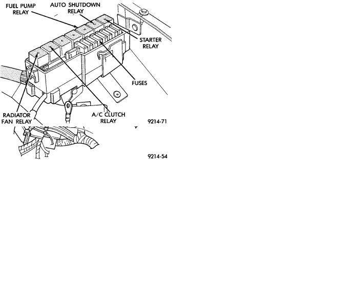
On AA body vehicles, the relay is located on the drivers side inner fender panel (Fig. 16). On AG Body vehicles, the relay is located in the power distribution center (Fig. 17).
Fig. 16 Relay LocationÐAA Body
Fig. 17 Relay LocationÐAG Body
ALTERNATOR FIELDÐENGINE CONTROLLER OUTPUT
The engine controller regulates the charging system voltage within a range of 12.9 to 15.0 volts. Refer to Group 8A for charging system information.
AUTO SHUTDOWN (ASD) RELAY AND FUEL PUMP RELAYÐENGINE CONTROLLER OUTPUT
The engine controller operates the auto shutdown (ASD) relay and fuel pump relay through one ground path. The controller operates the relays by switching the ground path on and off. Both relays turn on and off at the same time.

Ä
The ASD relay connects battery voltage to the fuel injector and ignition coil. The fuel pump relay connects battery voltage to the fuel pump and oxygen sensor heating element.
The engine controller turns the ground path off when the ignition switch is in the Off position. Both relays are off. When the ignition switch is in the On or Crank position, the controller monitors the crankshaft and camshaft sensor signals to determine engine speed and ignition timing (coil dwell). If the engine controller does not receive the crankshaft and camshaft signals when the ignition switch is in the Run position, it will de-energize both relays. When the relays are de-energized, battery voltage is not supplied to the fuel injector, ignition coil, fuel pump and oxygen sensor heating element.
On AA body vehicles, the ASD relay and fuel pump relay are mounted on the drivers side fender well (Fig. 16).
On AG body vehicles, the ASD relay and fuel pump relay are located in the power distribution center (Fig. 17).
AUTOMATIC IDLE SPEED (AIS) MOTORÐENGINE CONTROLLER OUTPUT
The idle speed stepper (AIS) motor is mounted on the throttle body (Fig. 14). The engine controller operates the AIS motor. The engine controller adjusts engine idle speed through the AIS to compensate for engine load or ambient conditions.
The throttle body has an air bypass passage that provides air for the engine at idle (the throttle blade is closed). The AIS motor pintle protrudes into the air bypass passage and regulates air flow through it.
The engine controller adjusts engine idle speed by moving the AIS motor pintle in and out of the bypass passage. The adjustments are based on inputs the controller receives. The inputs are from the throttle position sensor, camshaft sensor, crankshaft sensor, coolant temperature sensor, and various switch operations (brake and air conditioning). Deceleration die out is also prevented by increasing airflow when the throttle is closed quickly after a driving (speed) condition.
BAROMETRIC READ SOLENOIDÐENGINE CONTROLLER OUTPUT
The barometric pressure read solenoid is spliced into the manifold absolute pressure (MAP) sensor vacuum hose (Fig. 12). The barometric read solenoid switches the pressure supply to the MAP sensor from either barometric pressure (atmospheric) or manifold vacuum. The engine controller operates the solenoid.
Atmospheric pressure is periodically supplied to the MAP sensor to measure barometric pressure. This occurs at closed throttle, once per throttle closure but no more often than once every 3 minutes and within a
FUEL SYSTEMS 14 - 83
specified RPM band. Barometric information is used primarily for boost control and start fuel enrichment at various altitudes.
CANISTER PURGE SOLENOIDÐENGINE CONTROLLER OUTPUT
Vacuum for the Evaporative Canister is controlled by the Canister Purge Solenoid (Fig. 18). The solenoid is controlled by the engine controller.
Fig. 18 Canister Purge Solenoid and Wastegate
Control Solenoid
The engine controller operates the solenoid by switching the ground circuit on and off. When grounded, the solenoid energizes and prevents vacuum from reaching the evaporative canister. When not energized the solenoid allows vacuum to flow to the canister.
During warm-up and for a specified time period after hot starts the engine controller grounds the purge solenoid. Vacuum does not operate the evaporative canister valve.
The engine controller removes the ground to the solenoid when the engine reaches a specified temperature and the time delay interval has occurred. When the solenoid is de-energized, vacuum flows to the canister purge valve. Vapors are purged from the canister and flow to the throttle body.
The purge solenoid will also be energized during certain idle conditions, in order to update the fuel delivery calibration.
CHECK ENGINE LAMPÐENGINE CONTROLLER OUTPUT
The Check Engine Lamp comes on each time the ignition key is turned ON and stays on for 3 seconds as a bulb test. The Check Engine Lamp warns the operator that the engine controller has entered a Limp-in mode. During Limp-in-Mode, the controller attempts to keep the system operational. The check engine lamp signals the need for immediate service. In limp-in mode, the Engine controller compensates for the failure of certain components that send incor-

14 - 84 FUEL SYSTEMS
rect signals. The controller substitutes for the incorrect signals with inputs from other sensors.
Signals that can trigger the Check Engine Lamp.
²Coolant Temperature Sensor
²Manifold Absolute Pressure Sensor
²Throttle Position Sensor
²Battery Voltage Input
²An Emissions Related System
²Charging system
The Check Engine Lamp can also be used to display fault codes. Cycle the ignition switch on, off, on, off, on, within five seconds and any fault codes stored in the Engine controller will be displayed. Refer to On Board Diagnostics in the General DiagnosisÐ2.2L Turbo III Engines section of this Group for Fault Code Descriptions.
DIAGNOSTIC CONNECTORÐENGINE CONTROLLER OUTPUT
The diagnostic connector provides the technician with the means to connect the DRB II tester to diagnosis the vehicle.
FUEL INJECTORÐENGINE CONTROLLER OUTPUT
The Fuel Injectors are electric solenoids driven by the engine controller (Fig. 19).
Ä
sharp edge of the injector nozzle. The resulting fuel sprays forms a cone shaped pattern before entering the air stream.
Fuel is constantly supplied to the injector at regulated 380 Kpa (55 psi). Unused fuel returns to the fuel tank.
IGNITION COILÐENGINE CONTROLLER OUTPUT
The Direct Ignition System (DIS) uses a molded coil (Fig. 20). The coil is mounted on the front of the engine. High tension leads route to each cylinder from the coil. The coil fires two spark plugs every power stroke. One plug is the cylinder under compression, the other cylinder fires on the exhaust stroke. The engine controller determines which of the coils to charge and fire at the correct time.
Fig. 19 Fuel Injector
Based on sensor inputs, the engine controller determines when and how long the fuel injector should operate. The amount of time an injector fires is referred to as injector pulse width. The auto shutdown (ASD) relay supplies battery voltage to the injector. The engine controller supplies the ground path. By switching the ground path on and off, the engine controller adjusts injector pulse width.
When the controller supplies a ground path, a spring loaded needle or armature lifts from its seat. Fuel flows through the orifice and deflects off the
Fig. 20 Ignition Coil
The auto shutdown (ASD) relay provides battery voltage to the ignition coil. The engine controller provides a ground contact (circuit) for energizing the coil. When the controller breaks the contact, the energy in the coil primary transfers to the secondary causing the spark. The engine controller will de-energize the ASD relay if it does not receive the crankshaft sensor and camshaft sensor inputs. Refer to Auto Shutdown (ASD) Relay/Fuel Pump RelayÐEngine Controller Output in this section for relay operation.
RADIATOR FAN RELAYÐENGINE CONTROLLER OUTPUT
The radiator fan is energized by the engine controller through the radiator fan relay. The engine controller grounds the radiator fan relay when engine coolant reaches a predetermined temperature. For more information, refer to Group 7, Cooling Systems.
On AG body vehicles, the radiator fan relay is located in the power distribution center (Fig. 17). Refer to the Wiring and Component Identification section of Group 8W.