


14 - 48 FUEL SYSTEMS |
|
Ä |
|
Fig. 1 Electronic Fuel Injection Components
engine controller adjusts the air-fuel ratio by changing injector pulse width. Injector pulse width is the time an injector is energized.
SYSTEM DIAGNOSIS
The engine controller tests many of its own input and output circuits. If a fault is found in a major system, the information is stored in memory. Technicians can display fault information through the instrument panel Check Engine lamp or by connecting the Diagnostic Readout Box II (DRB II). For fault code information, refer to On Board Diagnostics in 2.5L Turbo I Multi-Point Fuel InjectionÐGeneral Diagnosis section of this group.
CCD BUS
Various controllers and modules exchange information through a communications port called the CCD Bus. The engine controller transmits vehicle load data on the CCD Bus.
ENGINE CONTROLLER
The engine controller is a digital computer containing a microprocessor (Fig. 2). The controller receives input signals from various switches and sensors that are referred to as Engine Controller Inputs. Based on these inputs, the controller adjusts various engine
and vehicle operations through devices that are referred to as Engine Controller Outputs.
Fig. 2 Engine Controller
Engine Controller Inputs:
²Air Conditioning Controls
²Battery Voltage
²Brake Switch
²Coolant Temperature Sensor
²Detonation (Knock) Sensor
²Distributor (Hall Effect) Pick-up
²Manifold Absolute Pressure (MAP) Sensor

Ä
²Oxygen Sensor
²SCI Receive
²Speed Control System Controls
²Throttle Position Sensor
²Park/Neutral Switch (automatic transmission)
²Vehicle Distance (Speed) Sensor
Engine Controller Outputs:
²Air Conditioning Clutch Relay
²Alternator Field
²Automatic Idle Speed (AIS) Motor
²Auto Shutdown (ASD) Relay
²Barometric Read Solenoid
²Canister Purge Solenoid
²Check Engine Lamp
²Diagnostic Connector
²Fuel Injector
²Ignition Coil
²Part Throttle Unlock Solenoid (Automatic Transmission)
²Radiator Fan Relay
²Speed Control Solenoids
²Tachometer Output
²Wastegate Solenoid
Based on inputs it receives, the engine controller adjusts fuel injector pulse width, idle speed, ignition spark advance, ignition coil dwell and canister purge operation. The engine controller regulates operation of the cooling fan, A/C and speed control systems. The controller changes alternator charge rate by adjusting the alternator field.
The engine controller adjusts injector pulse width (air-fuel ratio) based on the following inputs.
²battery voltage
²coolant temperature
²detonation sensor
²exhaust gas content
²engine speed (distributor pick-up)
²manifold absolute pressure
²throttle position
The engine controller adjusts ignition timing based on the following inputs.
²coolant temperature
²engine speed (distributor pick-up)
²manifold absolute pressure
²throttle position
The auto shutdown (ASD) and fuel pump relays are mounted externally. The engine controller turns both relays on and off through the same circuit.
The distributor pick-up signal is sent to the engine controller. If the engine controller does not receive a distributor signal within approximately one second of engine cranking, the ASD relay and fuel pump relay are deactivated. When these relays are deactivated, power is shut off from the fuel injector, fuel pump, ignition coil, and oxygen sensor heater element.
The engine controller contains a voltage converter that changes battery voltage to a regulated 9.0 volts
FUEL SYSTEMS 14 - 49
to power the distributor pick-up and vehicle speed sensor. The controller also provides a 5.0 volts supply for the coolant temperature sensor, manifold absolute pressure sensor and throttle position sensor.
AIR CONDITIONING SWITCH SENSEÐENGINE CONTROLLER INPUT
When the air conditioning or defrost switch is put in the ON position and the low pressure and high pressure switches are closed, the engine controller receives an input indicating that the air conditioning has been selected. After receiving this input, the engine controller activates the A/C compressor clutch by grounding the A/C clutch relay. The engine controller also adjusts idle speed to a scheduled RPM to compensate for increased engine load.
BATTERY VOLTAGEÐENGINE CONTROLLER INPUT
The engine controller monitors the battery voltage input to determine fuel injector pulse width and alternator field control.
If battery voltage is low the engine controller will increase injector pulse width (period of time that the injector is energized).
BRAKE SWITCHÐENGINE CONTROLLER INPUT
When the brake switch is activated, the engine controller receives an input indicating that the brakes are being applied. After receiving the input, the controller vents the speed control servo. Venting the servo turns the speed control system off.
COOLANT TEMPERATURE SENSORÐENGINE CONTROLLER INPUT
The coolant temperature sensor is installed behind the thermostat housing and ignition coil in the hot box. The engine controller supplies 5 volts to the coolant temperature sensor. The sensor provides an input voltage to the engine controller (Fig. 3). As coolant temperature varies, the coolant temperature sensor resistance changes resulting in a different input voltage to the engine controller.
The engine controller demands slightly richer airfuel mixtures and higher idle speeds until the engine reaches normal operating temperature.
This sensor is also used for cooling fan control.
DETONATION SENSOR (KNOCK SENSOR)ÐENGINE CONTROLLER INPUT
The detonation sensor generates a signal when spark knock occurs in the combustion chambers. The sensor is mounted on the intake manifold (Fig. 4). The sensor provides information used by the engine controller to modify spark advance and boost schedules in order to eliminate detonation.

14 - 50 FUEL SYSTEMS
Fig. 3 Coolant Temperature Sensor
Fig. 4 Detonation Sensor
DISTRIBUTOR (HALL EFFECT) PICK-UPÐENGINE CONTROLLER INPUT
The distributor pick-up supplies engine speed to the engine controller. The distributor pick-up is a Hall Effect device (Fig. 5).
A shutter (sometimes referred to as an interrupter) is attached to the distributor shaft. The shutter contains four blades, one per engine cylinder. A switch plate is mounted to the distributor housing above the shutter. The switch plate contains the distributor pick-up (a Hall Effect device and magnet) through which the shutter blades rotate. As the shutter blades pass through the pick-up, they interrupt the magnetic field. The Hall effect device in the pick-up senses the change in the magnetic field and switches on and off (which creates pulses), generating the input signal to
Ä
Fig. 5 Distributor Pick-UpÐTypical
the engine controller. The engine controller calculates engine speed through the number of pulses generated.
One of the shutter blades has a window cut into it. The window tells the engine controller which injector to energize. Also, the controller uses the input for control of detonation.
MANIFOLD ABSOLUTE PRESSURE (MAP) SENSORÐENGINE CONTROLLER INPUT
The engine controller supplies 5 volts to the MAP sensor. The MAP sensor converts intake manifold pressure into voltage. The engine controller monitors the MAP sensor output voltage. As vacuum increases, MAP sensor voltage decreases proportionately. Also, as vacuum decreases, MAP sensor voltage increases proportionately.
During cranking, before the engine starts running, the engine controller determines atmospheric air pressure from the MAP sensor voltage. While the engine operates, the controller determines intake manifold pressure from the MAP sensor voltage.
Based on MAP sensor voltage and inputs from other sensors, the engine controller adjusts spark advance and the air/fuel mixture.
The MAP sensor mounts on the dash panel inside the engine compartment (Fig. 6). A vacuum hose connects the sensor to the throttle body.
OXYGEN SENSOR (O2 SENSOR)ÐENGINE CONTROLLER INPUT
The O2 sensor is located in the exhaust manifold and provides an input voltage to the engine controller (Fig. 7). The input tells the engine controller the oxygen content of the exhaust gas. The engine con-
Ä |
|
FUEL SYSTEMS 14 - 51 |
|
Fig. 6 Manifold Absolute Pressure (MAP) Sensor
Location
troller uses this information to fine tune the air-fuel ratio by adjusting injector pulse width.
system to enter into closed loop operation sooner. Also, it allows the system to remain in closed loop operation during periods of extended idle.
In Closed Loop operation the engine controller monitors the O2 sensor input (along with other inputs) and adjusts the injector pulse width accordingly. During Open Loop operation the engine controller ignores the O2 sensor input. The controller and adjusts injector pulse width based on a preprogrammed (fixed) oxygen sensor input value and inputs from other sensor.
SPEED CONTROLÐENGINE CONTROLLER INPUT
The speed control system provides four separate voltages (inputs) to the engine controller. The voltages correspond to the On/Off, Set, and Resume.
The speed control ON voltage informs the engine controller that the speed control system has been activated. The speed control SET voltage informs the controller that a fixed vehicle speed has been selected. The speed control RESUME voltage indicates the previous fixed speed is requested. The speed control OFF voltage tells the controller that the speed control system has deactivated. Refer to Group 8H for further speed control information.
TRANSMISSION PARK/NEUTRAL SWITCHÐENGINE CONTROLLER INPUT
The park/neutral switch is located on automatic transmission housing (Fig. 8). Manual transmission do not use park/neutral switches. The switch provides an input to the engine controller. The input indicates if the automatic transmission is in Park, Neutral, or a drive gear selection. The input is used to determine idle speed (varying with gear selection), fuel injector pulse width, and ignition timing advance. The park neutral switch is sometimes referred to as the neutral safety switch.
Fig. 7 Oxygen Sensor
The O2 sensor produces voltages from 0 to 1 volt, depending upon the oxygen content of the exhaust gas in the exhaust manifold. When a large amount of oxygen is present (caused by a lean air-fuel mixture), the sensor produces a low voltage. When there is a lesser amount present (rich air-fuel mixture) it produces a higher voltage. By monitoring the oxygen content and converting it to electrical voltage, the sensor acts as a rich-lean switch.
The oxygen sensor is equipped with a heating element that keeps the sensor at proper operating temperature during all operating modes. Maintaining correct sensor temperature at all times allows the
Fig. 8 Park Neutral Switch
THROTTLE POSITION SENSOR (TPS)ÐENGINE CONTROLLER INPUT
The Throttle Position Sensor (TPS) is mounted on the throttle body and connected to the throttle blade shaft (Fig. 9). The TPS is a variable resistor. The sensor provides the engine controller with an input

14 - 52 FUEL SYSTEMS
signal (voltage) representing throttle blade position. As the position of the throttle blade changes, the resistance of the TPS changes.
Fig. 9 Throttle Position Sensor (TPS) and Automatic
Idle Speed Motor (AIS)
The engine controller supplies approximately 5 volts to the TPS. The TPS output voltage (input signal to the engine controller) represents the throttle blade position. The engine controller receives an input signal voltage from the TPS varying in an approximate range of from 1 volt at minimum throttle opening (idle) to 4 volts at wide open throttle. Along with inputs from other sensors, the engine controller uses the TPS input to determine current engine operating conditions. The engine controller adjusts fuel injector pulse width and ignition timing based on these inputs.
Ä
exists. Under deceleration conditions, the engine controller adjusts the AIS motor to maintain a desired MAP value. Under idle conditions, the engine controller adjusts the AIS motor to maintain a desired engine speed.
AIR CONDITIONING (A/C) CLUTCH RELAYÐENGINE CONTROLLER OUTPUT
The engine controller operates the air conditioning clutch relay ground circuit. The radiator fan relay supplies battery power to the solenoid side of the A/C clutch relay. The air conditioning clutch relay will not energize unless the radiator fan relay energizes. The engine controller energizes the radiator fan relay when the air conditioning or defrost switch is put in the ON position and the low pressure and high pressure switches close.
With the engine operating, the engine controller cycles the air conditioning clutch on and off when the A/C switch closes with the blower motor switch in the on position. When the engine controller senses low idle speeds or wide open throttle through the throttle position sensor, it de-energizes the A/C clutch relay. The relay contacts open, preventing air conditioning clutch engagement.
On AG and AJ models, the A/C clutch relay is located in the power distribution center. Refer to the Wiring and Component Identification section of Group 8W.
ON AA and AP models, the A/C clutch relay is mounted to the inner fender panel, next to the drivers side strut tower (Fig. 11).
VEHICLE DISTANCE (SPEED) SENSORÐENGINE CONTROLLER INPUT
The distance sensor (Fig. 10) is located in the transmission extension housing. The sensor input is used by the engine controller to determine vehicle speed and distance traveled.
Fig. 10 Vehicle Distance (Speed) Sensor |
|
The distance sensor generates 8 pulses per sensor |
Fig. 11 Relay Identification |
revolution. These signals, along with a closed throttle |
|
signal from the TPS, determine if a closed throttle |
|
deceleration or normal idle condition (vehicle stopped) |
|
Ä
ALTERNATOR FIELDÐENGINE CONTROLLER OUTPUT
The engine controller regulates the charging system voltage within a range of 12.9 to 15.0 volts. Refer to Group 8A for charging system information.
AUTO SHUTDOWN (ASD) RELAY AND FUEL PUMP RELAYÐENGINE CONTROLLER OUTPUT
The engine controller operates the auto shutdown (ASD) relay and fuel pump relay through one ground path. The controller operates the relays by switching the ground path on and off. Both relays turn on and off at the same time.
The ASD relay connects battery voltage to the fuel injector and ignition coil. The fuel pump relay connects battery voltage to the fuel pump and oxygen sensor heating element.
The engine controller turns the ground path off when the ignition switch is in the Off position. Both relays are off. When the ignition switch is in the On or Crank position, the engine controller monitors the distributor pick-up signal to determine engine speed and ignition timing (coil dwell). If the controller does not receive a distributor signal when the ignition switch is in the Run position, it de-energizes both relays. Battery voltage is not supplied to the fuel injector, ignition coil, fuel pump and oxygen sensor heating element.
On AG and AJ models, the ASD relay and fuel pump relay are located in the power distribution center. Refer to the Wiring and Component Identification section of Group 8W.
On AA and AP models, the ASD relay and fuel pump relay are mounted on the drivers side fender well, next to the strut tower (Fig. 11).
AUTOMATIC IDLE SPEED (AIS) MOTORÐENGINE CONTROLLER OUTPUT
The idle speed stepper motor is mounted on the throttle body and is controlled by the engine controller (Fig. 9). The engine controller adjusts engine idle speed through the AIS motor to compensate for engine load or ambient conditions.
The throttle body has an air bypass passage that provides air for the engine at idle (the throttle blade is closed). The AIS motor pintle protrudes into the air bypass passage and regulates air flow through it.
The engine controller adjusts engine idle speed by moving the AIS motor pintle in and out of the bypass passage. The adjustments are based on inputs the controller receives from the throttle position sensor, speed sensor (distributor pick-up coil), coolant temperature sensor, and various switch operations (brake, park/neutral, air conditioning). Deceleration die out is also prevented by increasing airflow when the throttle is closed quickly after a driving (speed) condition.
FUEL SYSTEMS 14 - 53
BAROMETRIC READ SOLENOIDÐENGINE CONTROLLER OUTPUT
The barometric pressure read solenoid is tied into the manifold absolute pressure (MAP) sensor vacuum hose (Fig. 6). The barometric read solenoid switches the pressure supply to the MAP sensor from either barometric pressure (atmospheric) or manifold vacuum. The engine controller operates the solenoid.
Atmospheric pressure is periodically supplied to the MAP sensor to measure barometric pressure. This occurs at closed throttle, once per throttle closure but no more often than once every 3 minutes and within a specified RPM band. Barometric information is used primarily for boost control.
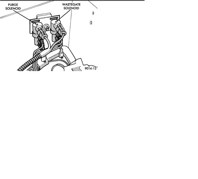
CANISTER PURGE SOLENOIDÐENGINE CONTROLLER OUTPUT
Vacuum for the Evaporative Canister is controlled by the Canister Purge Solenoid (Fig. 12). The solenoid is controlled by the engine controller.
Fig. 12 Canister Purge Solenoid and Wastegate
Control Solenoid
The engine controller operates the solenoid by switching the ground circuit on and off. When energized, the solenoid prevents vacuum from reaching the evaporative canister. When not energized the solenoid allows vacuum to flow to the canister.
During warm-up and for a specified time period after hot starts, the controller grounds the purge solenoid. When the solenoid energizes, vacuum does not operate the evaporative canister valve.
The engine controller removes the ground to the solenoid when the engine reaches a specified temperature and the time delay interval has occurred. When the solenoid is de-energized, vacuum flows to the canister purge valve. Vapors are purged from the canister and flow to the throttle body.
The purge solenoid will also be energized during certain idle conditions, in order to update the fuel delivery calibration.

14 - 54 FUEL SYSTEMS
CHECK ENGINE LAMPÐENGINE CONTROLLER OUTPUT
The Check Engine Lamp comes on each time the ignition key is turned ON and stays on for 3 seconds as a bulb test. The Check Engine Lamp warns the operator that the engine controller has entered a Limp-in mode. During Limp-in-Mode, the controller attempts to keep the system operational. The check engine lamp signals the need for immediate service. In limp-in mode, the Engine controller compensates for the failure of certain components that send incorrect signals. The controller substitutes for the incorrect signals with inputs from other sensors.
Signals that can trigger the Check Engine Lamp.
²Coolant Temperature Sensor
²Manifold Absolute Pressure Sensor
²Throttle Position Sensor
²Battery Voltage Input
²An Emissions Related System
²Charging system
The Check Engine Lamp can also be used to display fault codes. Cycle the ignition switch on, off, on, off, on, within five seconds to display any fault codes stored in the controller. Refer to On Board Diagnostics in the General DiagnosisÐ2.5L Turbo I Engines section of this Group for Fault Code Descriptions.
DIAGNOSTIC CONNECTORÐENGINE CONTROLLER OUTPUT
The diagnostic connector provides the technician with the means to connect the DRB II tester to diagnosis the vehicle.
Ä
Fig. 13 Fuel Injector
controller breaks the contact, the energy in the coil primary transfers to the secondary causing the spark. The engine controller will de-energize the ASD relay if it does not receive an input from the distributor pick-up. Refer to Auto Shutdown (ASD) Relay/Fuel Pump RelayÐEngine Controller Output in this section for relay operation.
The ignition coil is mounted on the hot box next to the thermostat housing (Fig. 14).
FUEL INJECTORÐENGINE CONTROLLER OUTPUT
The Fuel Injectors are electric solenoids driven by the engine controller (Fig. 13).
Based on sensor inputs, the engine controller determines when and how long the fuel injector should operate. The amount of time an injector fires is referred to as injector pulse width. The auto shutdown (ASD) relay supplies battery voltage to the injector. The engine controller supplies the ground path. By switching the ground path on and off, the engine controller adjusts injector pulse width.
When the controller supplies a ground path, a spring loaded needle or armature lifts from its seat. Fuel flows through the orifice and deflects off the sharp edge of the injector nozzle. The resulting fuel sprays forms a cone shaped pattern before entering the air stream.
Fuel is constantly supplied to the injector at regulated 380 Kpa (55 psi). Unused fuel returns to the fuel tank.
IGNITION COILÐENGINE CONTROLLER OUTPUT |
Fig. 14 Ignition Coil |
||
The engine controller provides a |
ground contact |
||
|
|||
(circuit) for energizing the ignition |
coil. When the |
|
|