- •1 Introduction
- •2 Bistable Systems Theory
- •2.1 Bistable system properties
- •2.2 Steady State Dynamics of Bistable Systems
- •2.3 Mechanical Demonstrator
- •2.4 Bistable System Discretisation
- •3 Bistable Digital Audio Effect
- •3.1 Steady-state Dynamics
- •3.2 Potential Energy and Force-Displacement Relationship
- •3.3 Digital Effect Implementation
- •3.4 VST Plugin and Online Demo Application
- •4 Conclusion
- •5 Acknowledgments
- •6 References

Proceedings of the 23rd International Conference on Digital Audio Effects (DAFx2020), Vienna, Austria, September 2020-21
BISTABLE DIGITAL AUDIO EFFECT
Alexander Ramirez, Vikas Tokala, Antonin Novak, Frederic Ablitzer and Manuel Melon
Laboratoire d’Acoustique de l’Université du Mans LAUM - UMR 6613 CNRS, Le Mans Université,
Avenue Olivier Messiaen, 72085 LE MANS CEDEX 9, France antonin.novak@univ-lemans.fr
ABSTRACT
A mechanical system is said to be bistable when its moving parts can rest at two equilibrium positions. The aim of this work is to model the vibration behaviour of a bistable system and use it to create a sound effect, taking advantage of the nonlinearities that characterize such systems. The velocity signal of the bistable system excited by an audio signal is the output of the digital effect. The latter is coded in C++ language and compiled into VST3 format that can be run as an audio plugin within most of the commercial digital audio workstation software in the market and as a standalone application. A Web Audio API demonstration is also available online as a support material.
1. INTRODUCTION
unique sounds driven by the nonlinear features of the system. Bistability, a phenomenon that arises in many real-world systems, means that a dynamical system can have two stable equilibrium states [13]. Such a system can lead to many kinds of nonlinear behaviours [14] and consequently to many interesting effects that can be implemented in digital domain.
2. BISTABLE SYSTEMS THEORY
This section describes the theory of bistable systems. It starts with a brief introduction to monostable linear and nonlinear systems with transitions into the bistable nonlinear systems and their properties. A mechanical prototype was build and video-recorded as a pedagogical support for the theory. The bistable system is next written in form of difference equations.
When the first audio effects were introduced into the market, musicians, composers, filmmakers, and audio engineers started experimenting with these gadgets obtaining new exotic and fascinating sounds that would revolutionize music forever. Since then, many enthusiasts have dedicated extensive hours to creating and synthesizing new sounds that can be used for musical compositions and for audiovisual productions. With the rapid development of the computer industry and digitalization of analogue audio effects [1], it has become even easier to experiment with them.
Many of these effects are using some nonlinear relation, which is of no surprise. Indeed, many beautiful sounds created by musical instruments rely very often on a nonlinear mechanism. Selfsustained oscillations in instruments like violins, flutes or trumpets, depend upon a severe nonlinearity [2, 3]. Even instruments based on free oscillations can exhibit nonlinear behaviour, for instance, due to vibrations of strings at large amplitude [4] or against unilateral contact obstacle [5]. Percussion instruments like cymbals or gongs may even exhibit chaotic behaviour [6, 7], an extreme form of nonlinear behaviour.
Many of the nonlinear digital audio effects are based on purely mathematical models going from simple static or dynamic nonlinear functions [1] to more complicated block-oriented models [8, 9]. Other nonlinear effects are based on physics [10, 11] or on modern techniques such as deep learning [12] to imitate the physics.
This work aims to study the main properties of bistable systems, that are described in section 2, and implement them into a real-time digital audio effect (section 3) capable of generating
Copyright: © 2020 Alexander Ramirez et al. This is an open-access article distributed under the terms of the Creative Commons Attribution 3.0 Unported License, which permits unrestricted use, distribution, and reproduction in any medium, provided the original author and source are credited.
2.1. Bistable system properties
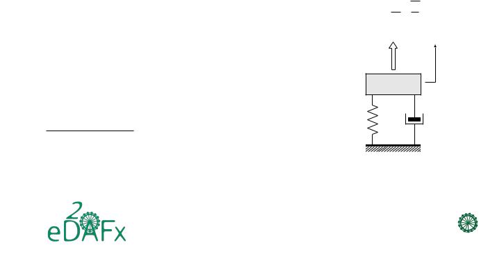
To understand what a bistable system is and how it works, one can start with a simple one degree of freedom (1DOF) linear massspring system (Fig. 1) with well known equations. It consists of a mass m connected to the ground by a linear spring of stiffness value k and a damper of value c. It is excited by an external force f, and x is the displacement of the mass. The equation of motion of such a system is [15]
mx¨ + cx˙ + kx = f(t), |
(1) |
where x ≡ x(t) is a function of time and where x˙ and x¨ represent the first and second time derivative, respectively. The resonance frequency of such a system is expressed as
f0 |
= 2π rm. |
(2) |
|
|
1 |
k |
|
|
f |
|
x |
|
m |
|
|
k |
c |
|
|
Figure 1: Damped mass-spring system.
DAFx.1
109
2 in21
DAFx

Proceedings of the 23rd International Conference on Digital Audio Effects (DAFx2020), Vienna, Austria, September 2020-21
x = −a |
stable |
x = a |
|
equilibrium |
|||
|
|||
d |
|
|
|
d |
|
|
|
|
|
l0 |
|
f |
unstable |
|
|
|
equilibrium |
|
|
|
x = 0 |
|
stable equilibria |
unstable equilibrium |
Figure 3: Force Displacement Relationship of a bistable system.
Figure 2: Bistable system.
By introducing a nonlinear stiffness, the monostable linear system can become nonlinear [16]. The equation that describes such a system, called the Duffing equation [17], is
mx¨ + cx˙ + αx + βx3 = f(t), |
(3) |
where β is the nonlinear stiffness parameter. Such a system can also be used to generate audio effects [18, 19].
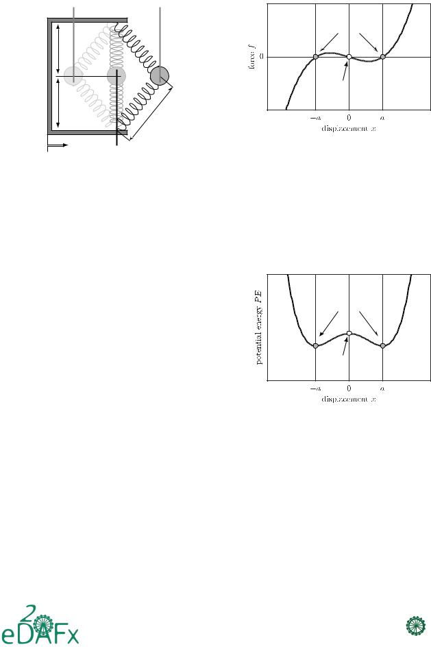
A bistable system can be obtained by adjusting the values of α and β in Eq. (3), as explained below. A 1DOF scheme of a bistable system is shown in Fig. 2. The system is presented as a mass attached by two fixed springs, whose free length l0 (length of the spring when it is not under tension) is greater than the halfwidth of the frame [13], i.e. l0 > d, a necessary condition for this system to be bistable. This structure exhibits two equidistant stable positions and an unstable region in between them. If l0 ≤ d the system is monostable. The excitation force f in this system is applied from the base, which generates a mass displacement as a consequence.
The governing equation of motion of a bistable system is
mx¨ + cx˙ − k1x + k3x3 = f(t), |
(4) |
where f(t) is the excitation force, x defines the displacement of the mass, m is the mass, c is the damping factor, and k1 and k3 determine the nonlinear stiffness. Note, that a bistable system is a special type of the more general Duffing System with a negative linear stiffness coefficient.
Essentially, the bistable system behaves as a monostable system with a nonlinear stiffness (stiffness depending on displacement) expressed as a polynomial in the terms −k1x+k3x3, shown in Fig. 3. The curve obtained represents the relationship between the force f and mass displacement x of the system.
The elastic potential energy for the nonlinear stiffness, de-
R
termined by F (x)dx, where F (x) are the conservative forces
F (x) = −k1x + k3x3, is
P E = − |
1 |
|
2 |
|
1 |
4 |
(5) |
|
k1 x |
|
+ |
|
k3 x . |
||
2 |
|
4 |
The lowest points on the energy potential curve shown in Fig. 4 indicate the two stable positions of the system. It also shows that the system is unstable in between these positions, and with a small perturbation, it is forced to move to one of the stable positions.
It can be noted that the potential energy is maximum at the unstable position, which prompts the system to move towards stable positions with minimal energy input. This is also a unique characteristic of the bistable system.
stable equilibria |
unstable equilibrium |
Figure 4: Stored Potential Energy of a bistable system.
2.2. Steady State Dynamics of Bistable Systems
One of the main characteristics of bistable systems is the presence of different steady-state dynamics resulting from the same excitation conditions. Particularly, this means that the dynamics of the system can exhibit different behaviour in two experiments, even if the excitation conditions are the same. The specific dynamic that occurs in the system is also dependent on the initial conditions.
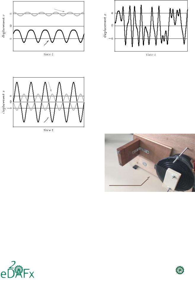
Commonly, they can be grouped into two regimes, intrawell and interwell oscillations. The intrawell oscillations occur when the mass vibrates around one of the two stable positions. The interwell oscillations occur when the mass vibrates across the unstable position. Figs. 5 and 6 show the expected behaviour of the intrawell and interwell oscillations.
DAFx.2
110
2 in21
DAFx

Proceedings of the 23rd International Conference on Digital Audio Effects (DAFx2020), Vienna, Austria, September 2020-21
low amplitude |
intrawell displacement |
high amplitude |
intrawell displacement |
Figure 5: Intrawell Oscillations of a bistable system.
low amplitude interwell displacement |
high amplitude interwell displacement |
Figure 7: Chaotic Oscillations of a bistable system.
tion, an old speaker was salvaged, and the cone and surround were removed. A 3D printed cylindrical cap is fitted with a clamping mechanism made from wood. A 3D printed spider is used to keep the actuating cylindrical cap in place and also to prevent the collision of the coil former to sides of the magnet. The membrane is fixed between two wooden clamps. When the loudspeaker is fed with a signal, it makes the former clamp-cap assembly move and, in turn, excites the bistable membrane.
The entire assembly is mounted on a wooden platform for better stability. A video recording of this mechanical system demonstrating the intrawell and interwell oscillations is available online at https://ant-novak.com/bistable_effect [21].
Figure 6: Interwell Oscillations of a bistable system.
A system dynamic where the system moves from one stable equilibrium to another crossing the unstable zero displacement position is called a snapthrough. Interwell oscillations are made of these snapthroughs.
Some nonlinear systems can oscillate aperiodically when subjected to sinusoidal excitations. In contrast with noise-induced behaviours, this characteristic is not random and can be determined with the equation that describes the bistable system. An example of this chaotic effect is shown in Fig. 7. In this figure, one can notice chaotic fluctuations in the displacement around the stable (intrawell oscillations) and unstable position (interwell oscillations).
2.3. Mechanical Demonstrator
To support the above-mentioned theory, a mechanical demonstrator was made and video recorded. The aim of this demonstrator is purely pedagogical: to demonstrate the dynamics of a bistable system by visualizing its motion through a real-world mechanical system.
The demonstrator is made of a post-buckled beam with central mass [20]. A rectangle cut out from a transparent plastic sheet (hereafter referred to as the membrane) was assembled with a metal washer, as shown in Fig. 8. To generate mechanical actua-
bistable membrane
Figure 8: A picture of the mechanical prototype to demonstrate the bistable system dynamics, video online at https: //ant-novak.com/bistable_effect [21].
2.4. Bistable System Discretisation
Since the objective of this work is to implement a bistable system in the digital domain we need to transform the governing differential equation of bistable system (Eq. (4)) to a difference equation. This is done using difference equation approximation [22] by set-
DAFx.3
111
2 in21
DAFx
