

Chapter
3 Systems of PWR Nuclear Power Plants
local power to the average power is defined as Fq) of the reactor is
also important. The factors
which affect the power distribution are the control rod movements
and the xenon distribution.
In the currently operating PWR plants, the constant
axial offset control method (CAOC operation method) is
adopted in controlling the power distribution; this reflects the
historical
development of PWRs, which included systematic increases of power
density, reconsideration of criteria for the ECCS and engineering
advances.
The CAOC operation method is aimed at preventing large distortions
in the core power distribution by flattening the axial power
distribution which depends mainly on the core conditions (the basic
characteristics are illustrated in Figure 3.3.18).
Primary
neutron
source
Section
B-B
Section
A-A
Section
B-B
Section
A-A
3-29
NSRA,
Japan
Figure 3.3.15 Reactivity worth of control group bank d (beginning of cycle, hot zero power, no xenon; example 4-loop core)

Figure 3.3.16 Structure of primary neutron source assembly


![]()

Figure 3.3.17 Structure of secondary neutron source assembly
In this operation method, the axial
offeet(AO),
as a core axial power distribution flattening index, is
defined as the ratio of the difference between the upper and lower
half core outputs over the total core output, and it is held within
a relatively small range.
The related nuclear design considerations are shown in Figure
3.3.19. In order to decrease (increase) the core output following a
load change in the secondary system, the control rods are inserted
(withdrawn) into (from) the reactor core. Consequently, the core
axial power distribution is significantly distorted and, if it is
allowed to stand, deviates from the limited range. This situation is
prevented by readjusting the boron concentration in the primary
coolant and, by using the control group rods to correct the power
distribution distortion. In the same period,
the reactivity effects of the changes in xenon concentration are
also compensated by chemical shim boron.
In the actual operation, instead of the axial offset,
AO., axial
imbalance, Al
(defined as: Al =
upper half core output - lower half core output = AO.x core output),
is used as the monitoring parameter of the core axial power
distribution. The Al is
observed by the out-of-core nuclear instrumentation system.
a. Basic design criteria of reload core
The number of fuel assemblies which are replaced by the new ones in
each subsequent core is determined on the basis of fuel burnup
history of the previous cycles and the amount of planned output for
the new cycle. The reload
core is designed by considering the following items. (D
The required fuel burnup (the amount of required electric power).
The number of fresh fuel assemblies and burnable poison rods.
The nuclear design requirements for safety assurance (c.f* section
3.3.2 (2)-b).
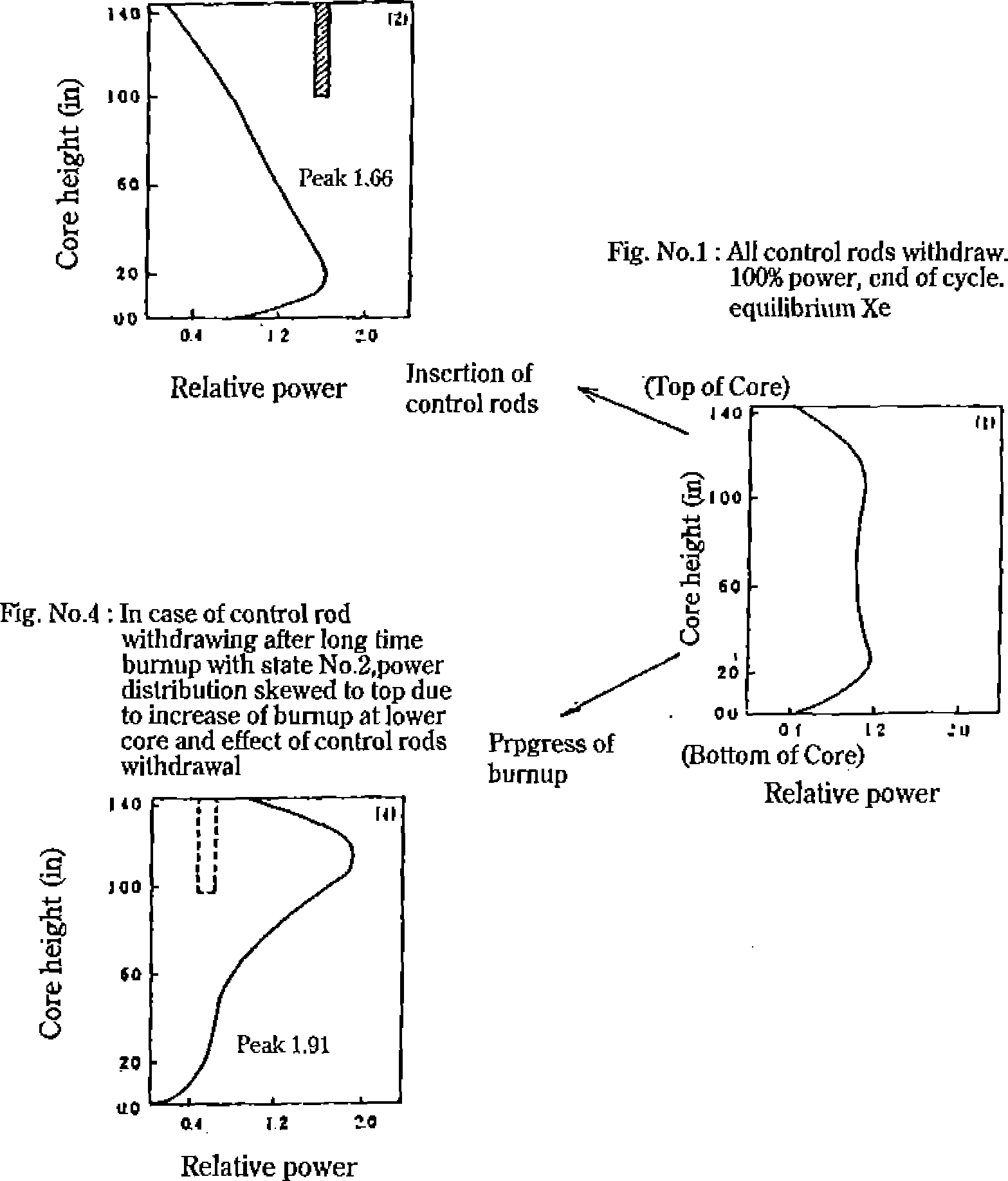
Fig.
No.2:
In case of control rod insertion from state No.l, power distribution
skewed to bottom
Figure
3.3.18
Effects of control rods position, power level, burnup distribution
and Xe on power distribution
Fig.
No,3:
In case of power decrease after long time burnup at state power
distribution skewed to top due to imbalance in moderator reactivity
effect
Xe effect
Fig.
No.5:
In case of power restoration after 6 hours at state No.3, power
distribution skewed to top due to xenon reduction at upper core,
even after returning to the same power as state No.l
Relative power
NSRA,
Japan
3-30
Core management

![]()

Chapter
3 Systems of PWR Nuclear Power Plants
b. Refueling pattern
The following main conditions are considered for selection of the
refueling pattern.
(D 'Hie quadrant symmetry
of the core must be maintained.
(D Proper loading of fuel
and burnable poison must consider the power distribution flattening
over the core life.
A positive moderator temperature coefficient must be avoided
through decreasing the critical boron concentration by loading
either fuel assemblies containing gadolinium, or burnable poison
rods. This is valid because at high critical concentration of
boron, the moderator temperature coefficient becomes positive.
The maximum fuel burn-up must not exceed the specified limits.
Control rods must provide the required control capability. That is
because the reactivity effect of the control rods depends on the
characteristics of the newly loaded fuel assemblies. Figure
3.3.20 compares a typical fuel
loading pattern for a reload core with an initial core
loading pattern.
Monitoring of nuclear and thermal conditions and burnup control
during the operation Thermal and nuclear conditions of the core are
monitored by using various detectors installed in and out of the
core. Out-of-core neutron detectors and thermocouples installed in
the upper part of the core are capable of continuous monitoring of
the core nuclear characteristics. In-core
neutron detectors are a movable type and in principle,
are used only once a month. The in-core neutron
Power
As shown in the left figure
the expected Fq x P might
exceed the design allowable limit due to big distorition of power
distribution in case of non-CAOC operation.

AO.-
P + P
1 r b
PT:
Top half core power PB
: Bottom half core power
Axial neutron flux
offset (Al)
Limiting condition
Limiting condition of axial
offset is determined so that Fq may not exceed the design allowable
limit.
Constant
axial
offset control
As shown in the left
figure,
the expected Fq x P
values stay within the
design
allowable limit
in case of CAO
C.
Figure
3.3.19 Essentials of constant axial offset control (CAOC) operation
method
3-31
NSRA,
Japan

Initial
Core Loading Pattern (example 3-Loop Core)
Reload
Core Loading Pattern (example 3-Loop Core)
Figure
3.3.20 Fuel loading patterns (examples)
detectors can be inserted into almost one third of the core fuel
assemblies (c.f. Figure 3.3.21) and therefore, obtain a reliable
core power distribution profile.
The burnup of each fuel assembly
is calculated from the core power distribution thus obtained and the
average core burnup which is obtained from the integrated core
output
Fuel integrity control during plant operation
The fuel integrity is controlled by routine sampling of the coolant
and determining its radioactivity. Special attention is given to the
radioactivity buildup of iodine-131 in the reactor coolant, from
which the integrity of fuel is confirmed. When the reactor load is
changed, the fuel is subject to local power changes to some
extent; however, by applying the CAOC
operation method, these local power changes can be maintained within
a relatively small range. A more
detailed discussion is given in section 3.3.1-(2) regarding the fuel
integrity during normal operation of the plant, including the load
changes periods.
Fuel inspection during the periodical inspection outage
During the periodical inspection outage of the plant, the fuel
assemblies (either spent or partially spent fuel) are removed from
the RV and are inspected by test equipment installed in the cask
loading pit, the spent fuel storage pit or the fuel test pit. Two
inspections are performed on the fuel assemblies. If it is
necessary, the presence of any leaks in the assemblies are examined
by sipping inspection.
External defects and dimensional changes of the fuel
assemblies are visually examined by underwater TV cameras. Not only
the integrity of the fuel is confirmed by these inspections, but, to
understand the fuel irradiation behavior in detail, some important
data such as irradiation growth of fuel rods and interred
spacing in fuel assembly are also measured by these underwater TV
cameras. These data are
evaluated and serve as design feedback data.
Trouble prevention measures related to fuel
The cause of the inter-rod spacing reduction in the fuel assembly is
fuel rod bending due to an irradiation effect In Japan, the local
integrity of fuel in the case of mutual contact of fuel rods is also
considered. In order to avoid such mutual contact of fuel rods and
to assure the fuel integrity during operation, visual and
dimensional inspections of the fuel are made.
An effective method to reduce the fuel rod bending is to increase
the number of the support grids and shorten the span length of fuel
rods. In newly-constructed plants, the numbers of grids in fuel
assemblies consisting of 14x14 (used in two- loop plants) and 17x17
{used in three- and four- loop plants) fuel rod arrays have been
increased from 7 to 8 and from 8 to 9, respectively. The effect has
been dramatic; no fuel rod bending defects have been seen in 14x14
type fuel assemblies with 8 grids and, only very slight fuel rod
bending was found in 17x17 type fuel assemblies with 9 grids.
NSRA,
Japan
3-32

![]()
Chapter
3 Systems of PWR Nuclear Power Plants
O
Instrumentation Thimbles
A,B,C,D,E In-core Neutron
Detectors
CAL In-core Neutron Detector
for Calibration
Figure
3.3.21 Arrangement of in-core neutron detectors (example 3-loop
core)
3-33
NSRA,
Japan
