*Changes
due to transients
[Source]
Mitsubishi open documents
so that, a permanent contact between the grid springs and the fuel
rods over the life of the fuel assemblies is maintained. In
addition, to avoid fuel rod contact with top and bottom nozzles (due
to fuel rod elongation during irradiation), sufficient end
clearances between rods and nozzles are provided.
Hold down forces of sufficient magnitude to oppose the dynamic lift
of the primary coolant flow on the fuel assemblies are obtained by
the leaf springs of the top nozzle. Besides the leaf spring forces,
loading imposed by rapid insertion of the control rods (scram) as
well as the hydraulic forces developed in the event of a postulated
LOCA are considered in design of the control rod guide thimbles. The
maximum impact force on the support grids for the design-basis
earthquake occurrence is calculated by a group vibration analyses
method and the results are compared with the experimental results to
ensure that the grid deformation will never disturb the insertion of
the control rods into the guide thimbles.
As shown in Figure 3.3.4, the structural elements of a PWR and the
reactor core consist of the RV,
fuel assemblies, core
internals (CI), rod cluster control (RCC) and control rod
drive mechanism (CRDM).
The initially loaded core is divided into regions of three different
enrichments. Fuel assemblies are arranged in a roughly cylindrical
pattern in the core. Light water is used as the primary coolant to
cool the core and moderate the neutrons at the same time. Boric
acid, a soluble neutron absorber, is used in the coolant to control
long term reactivity changes.
The reactor internals are designed to support the fuel assemblies in
the core and they are divided into two main parts, i.e., the lower
core structure and the upper core structure. The primary coolant
enters into the RV through the inlet nozzles located in the upper
section of the vessel, passes down through an annular passage
between the core barrel and the vessel wall (downcomer) to the lower
plenum formed by the bottom head, then enters the bottom of the core
and flows up to the upper plenum. The coolant temperature rises by
absorbing the heat generated in fuel rods while passing through the
NSRA,
Japan
3-20
Reactor and Reactor Core
Structure of reactor and reactor core
Chapter
3 Systems of PWR Nuclear Power Plants
Core
barret
Upper
core
support plate
Control
rod drive
mechanism
Reactor
vessel head
Upper
core plate
Thermal
shield
Core
baffle
Reactor
vessel
Fuel
assembly
Radial
support
Lower
core
support plate
Reactor
vessel
inlet
nozzle
Lower
core
support
plate
Lower
core
plate
Reactor
vessel
outlet
nozzle
Upper
core support column
Control
rod cluster
(withdrawn)
Figure
3.3.4 Reactor and internal structures core.
After mixing in the upper plenum, the coolant leaves the RV through
the outlet nozzles located on the same plane as the inlet nozzles.
The
upper core support structure, shown in Figure
3.3.5, consists of the upper core support plate, upper core plate,
rod cluster control (RCC)
Control
rod cluster
guide
Lube
guide tubes and thermocouples (for measuring the coolant
temperature). Hie upper
core support structure is positioned on the core barrel of the lower
core support structure by flat-sided pins pressed into the core
barrel. The major support structure of the reactor core is the lower
core support structure shown in Figure 3.3.6. The core barrel of the
lower core support structure provides an annular passageway for the
coolant flow.
In order to minimize the corrosion products and accompanying
radioactivity accumulation in the primary coolant, all parts which
are in direct contact with the reactor coolant are made of either
stainless steel or stainless steel-clad materials. The fuel cladding
is made from Zircaloy-4 or zirconium- based alloy which has
excellent corrosion resistance in addition to good nuclear
characteristics. Water quality in the closed cycle of the primary
cooling system is maintained to minimize corrosion. This is
accomplished by adjusting the pH of the water to a proper value
using lithium hydroxide (LiOH) and also, by supplying hydrogen gas
to the water to promote recombination of the free oxygen molecules
produced by dissociation of water molecules due to irradiation.
Figure
3.3.5 Upper core support structure
Figure
3.3.6 Lower core support structure
3-21
NSRA,
Japan


A summary of reactor and core specifications of Japanese
designed PWR NPPs is given in Table 3.3.3.
Core design
The reactor core is designed to produce a rated thermal power
throughout its specified lifetime without exceeding the safety
limits. In this regard, two main design objectives are
determination of the core size to obtain the rated thermal
output and safety assurance during normal operation and
accidents.
Determination of core size
The general design procedure of the reactor core size is shown
in Figure 3.3.7. The size of the reactor core basically depends
on the
thermal power objective and linear power density of the fuel
rods. Two conditions are set for determination of the number of
fuel assemblies: assuming a three-region-three-cycle
core; and keeping the symmetry of the core which implies that
the number of fuel assemblies in each region must be a multiple
of 4. In addition, one fuel assembly is necessary in the center
of the core. These conditions require that the total number of
the fuel assemblies must be equal to (4x3xN) +1 in which N is an
integer number. The core height should be determined by
considering the neutron economy which requires an equivalent
core diameter to core height ratio as close as possible to 1.
However, this criterion is not fully satisfied in the current
reactors, because the height of the
Table
3.3.3 Specifications of Japanese reactors and their cores |
2 |
3 |
4 |
||||
Electrical Power (MWe) |
340 |
500 |
559-579 |
826 |
870-890 |
1160-1180 |
|
Thermal Power (MWt) |
1031 |
1456 |
1650 |
2432 |
2652 |
3411 |
|
Core |
Equivalent diameter (m) |
2.47 |
2.47 |
2.47 |
3.04 |
3.04 |
3.37 |
Active height (m) |
3.05 |
. 3.66 |
3.66 |
3.66 |
3.66 |
3.66 |
|
Fuel Assembly |
Array |
14x14 |
14x14 |
14x14 |
15x15 |
17x17 |
17x17 |
No. of assemblies |
121 |
121 |
121 |
157 |
157 |
193 |
|
Fuel Rod |
Cladding outer diameter (mm) |
10.7 |
10.7 |
10.7 |
10.7 |
9.5 |
9.5 |
No. of rods/ assemblies |
179 |
179 |
179 |
204 |
264 |
264 |
|
Average Dnear Power (kW/m) |
15.4 |
17.9 |
20.3 |
20.2 |
17.1 |
17.9 |
|
Power Density (kW/m3) |
71 |
83 |
95 |
92 |
100 |
105 |
|
NPPs |
Mihama No.l |
Mihama No.2 |
Genkai No.l Genkai No.2 Ikata No.l Ikata No.2 Tomari No.l Tomari No.2 |
Takahama No.l Takahama No.2 Mihama No.3 |
Sendai No.l Sendai No.2 Takahama No.3 Takahama No,4 Ikata No.3 |
Ohi No.l Ohi No.2 Tsuruga No.l Ohi No.3 Ohi No,4 Genkai No.3 Genkai No.4 |
|
NSRA,
Japan
3~22
Chapter
3 Systems of PWR Nuclear Power Plants
Figure
3.3.7 Flow chart of core size determination
reactor core is standardized due to manufacturing reasons.
Nuclear design requirements for safety assurance
In order to ensure that the core has inherent safety provisions
through the provided negative reactivity coefficient, and the plant
has a sufficient shutdown margin, the following items are evaluated:
Sufficient shutdown margin is provided by two independent
reactivity control systems, i.e. by the RCC assemblies and by
injection of boric acid.
The design provides that the maximum reactivity
insertion rate corresponding to the maximum withdrawal rate of rod
cluster control (RCC) never exceeds its upper limit.
The design must guarantee
a negative reactivity
feedback (Doppler coefficient and moderator temperature coefficient)
characteristics of the core.
Further, the reactor core is designed so that the core power
distribution (power peaking coefficient) meets the criteria on fuel
temperature and critical heat
flux ratio (DNBR). After completion of the plant (i.e.
completion of
the test run and start of commercial operation),
refueling is conducted during the periodical inspection outages, for
which it is necessary to determine the next fuel loading pattern,
recalculate the core nuclear characteristics parameters and confirm
the safety of the core.
During reactor operation, it is necessary to trace the fuel burnup
through the recording and analyzing of various data (specially, core
output and core power distribution records). Fuel burnup information
is used as input data to determine the fuel loading pattern in the
next loading of the core.
The initially loaded core at the plant completion (first cycle core)
and the partially refueled core after each refueling operation
(second cycle, third cycle,...) are generally called the initial
core and reload
cores, respectively.
The initial core
The initial core is divided into three regions; each region is
loaded with fuel assemblies of different enrichment on the premise
of three- region-three-cycle refueling. The numbers of fuel
assemblies in each region are almost the same. The
fuel enrichment at each region is determined by considering the
following items. CD Planned unloading fuel burnup.
Larger operation cycles higher fuel enrichment
Sufficient flattening of power distribution.
Fuel assemblies with the highest enrichments (region 3) are placed
around the outside of the core (in a concentric circle) and the two
groups of assemblies of lower enrichments (regions 2 and 3) are
arranged in a selected pattern (checkerboard
pattern) in the central parts of the core. The initial
core is subject to three refueling operations which take place
generally in accordance with an inward loading schedule. Because the
initial core cycle contains more excess reactivity than subsequent
fuel cycles as a result of the loading of all-fresh fuel, burnable
poison rods are introduced to keep the negative moderator
temperature coefficient (this is done by reducing the soluble poison
concentration at the initial core cycle).
The reload cores
Reload core design calculations are carried out for each reload core
after the second cycle core, since the design conditions listed
below are different for different plants and different core
NSRA,
Japan
operating cycles.
(D Burnup of reloaded fuel
which depends on the operating conditions in the preceding cycle and
on the new loading pattern.
If any mechanical defect is detected in the fuel assemblies to be
reloaded, the defective
fuel assembly is replaced by a new one.
The burnup plan of the concerned cycle is determined by considering
the plan of electrical power supply during the operation cycle
period.
@ The enrichment of the
fresh fuel might be changed based on the long-term operation plan of
the reactor.
Thermal-hydraulic safety limits
The reactor is designed so that the minimum critical heat flux
ratio (DNBR) is always greater than a specified value. The
temperature difference of the heat transfer surface (temperature
difference between the coolant and the cladding surface) is
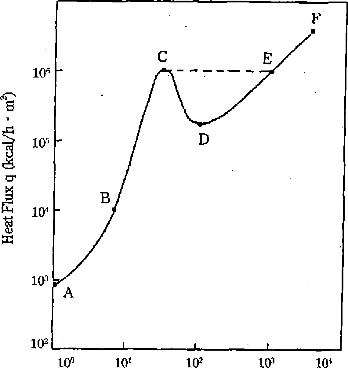
determined, as illustrated in Figure 3.3.8, by the heat
flux and heat transfer rate inclination
of the curve).
Boiling phenomena develop as: the subcooled region (A-B), where
boiling does not occur even with increasing heat flux (heat
generation); the nucleate Boiling region (B-C), where small bubbles
are vigorously formed at the heat transfer surface and detach from
the surface; and the film boiling region (E-F), where bubble number
increases rapidly and the bubbles become so numerous that they begin
to clump near the heating surface before finally forming a
continuous film of vapor over the surface in the D-E-F region (the
film boiling region). When the heat flux exceeds point C in the
figure, the heating surface temperature rise will suddenly jump into
region E-F dramatically not passing through the transition boiling
region (C-D) where partial
film boiling generally occurs.
Long-time operation at such high temperatures will possibly lead to
fuel failure due to clad deterioration. Therefore, the design has
the provision so that such a high clad surface temperature will
never be reached during the normal operation or under any
anticipated abnormal transient conditions.
The point C in the figure is defined as the DNB (departure from
nucleate boiling) point and the
Temperature Difference: Tw-Ts
• “C
'l\v:
Heat Transfer Surface
Temperature Ts: Saturation
Temperature
Figure
3.3.8 Boiling characteristics
corresponding heat flux is called the critical
heat flux (or DNB
heat flux). The
critical heat flux not only depends on local conditions such as
coolant flow, pressure and vapor content, but it also depends on
many other factors such as inlet enthalpy of coolant, channel
length, upstream channel shape and condition. For assessing the
thermal margin of the fuel in the core, the ratio of the critical
heat flux at a particular core location to the existing heat flux at
the same location (the critical
heat flux ratio: DNBR) is defined as nxmn
critical heat
flux local heat flux
DNBR is chosen as an index of the thermal margin of the fuels in the
core.
The fuel rods are designed such that the fuel center temperature is
less than the melting point of UO2.
This criterion is necessary to prevent the occurrence of the
following problems.
(T) Sudden expansion of the
uranium oxide fuel followed by pellet-clad interaction.
(2) Increase of the internal pressure of the cladding due to release
of fission gases.
©Chemical interaction
between fuel and cladding material.
Since the thermal conductivity of the UO2
fuel is
NSRA,
Japan
3-24