

The fuel
rod, as shown in Figure 3.3.1, consists of sintered
pellets of slightly-enriched uranium dioxide or
gadolinium-loaded uranium dioxide, stacked in a
Zircaloy-4 cladding tube. A stainless steel coil spring is inserted
into the top end of the zirconium-based alloy cladding and then,
both ends of the tube are closed by welding end plugs to them. The
fuel rods are filled with pressurized helium gas during the welding
process.
The cylindrical fuel pellets are formed by pressing the uranium
dioxide powder (or uranium dioxide with gadolinium-mixed powder) and
then they are sintered to about 97% theoretical density under
hydrogen atmosphere. Pellets are finished to the required size
(within a specified acceptable error margin) by grinding with SiC or
diamond wheels.
The ends of each pellet are dished to provide room to accommodate
the greater axial expansion at the center due to the temperature
gradient and the swelling
due to irradiation when in the core. Moreover, the edges of the
pellet end faces are chamfered to reduce the mechanical interaction
between the fuel pellets and the cladding.
In addition to the clearances between pellet and cladding, a plenum
volume is also provided in the upper part of the fuel rods. These
spaces relieve the increase of the internal gas pressure due to
release of fission gases from the fuel, and prevent development of
excessive cladding stresses caused by immediate contact between
pellet sand cladding as a result of thermal expansion and fuel
density change due to fuel burnup. A stainless steel coil spring is
inserted into the plenum space of the rod in order to prevent the
pellets from shifting and breaking down within the cladding, during
handling or shipping from their fabrication site to the NPP.
b. Fuel assemblies
As shown in Table 3.3.1 and Figure 3.3.1, the PWR fuel
assembly has a square cross-sectional structure
consisting of fuel rods, control
rod guide thimbles, spring-clip support grids, an in-core
instrumentation guide tube and the top and bottom
nozzles. The guide thimbles and instrumentation tube are made of
Zircaloy-4, the top and bottom nozzles are fabricated from stainless
steel and the top and bottom support
grids and leaf springs of the top nozzle are made from 718 class
Ni-based alloy (Inconel®
-718), and the middle support grids are made of
Zircaloy-4. The grid support structures are shown in Figure3.3.2.The
leaf springs of top nozzle are made of 718 class, a Ni-base alloy
(Jnconel®-718).
The supporting grids are assembled from thin plates of 718 class, a
Ni-base alloy (Inconel®-718) or Zircaloy-4 as shown in Figure3.3.2.
The control rod guide thimbles and in-core instrumentation tube are
fastened to the sleeves of the top and the intermediate support
grids by pipe-expanding work. Owing to such supporting structures,
fuel rods are properly supported in the fuel assembly, and
therefore, sufficient space is maintained for coolant stream while
permitting the axial thermal expansion and the irradiation growth of
fuel rods.
The main function of the top and bottom nozzles are: fixing the fuel
assembly in the reactor core, ensuring the coolant flow paths and
serving as a structural element of the fuel assembly*2.
In the gadolinium-loaded fuel assembly, a certain number of fuel
rods containing gadolinium are used. An example is shown in Figure
3.3.3.
The linear power density of a PWR fuel element (thermal power output
per unit length of fuel rod) is limited to a specified value in
order to maintain the fuel center temperature, the departure from
nucleate boiling ratio (DNB) and the surface
c*2)
The above description and explanatory drawings are valid for the
Westinghouse design-based fuel assembly known as the A-type fuel
assembly. There is another type, known as the B-type fuel assembly,
which is almost the same as that of the Ex-Babcock
& Wilcox design fuel assembly. The
most important differences between the A-type and B-type are as
follows. In the B-type assembly, the plenum volume is provided at
both the bottom and the top ends of the fuel rod and there is no
space between the fuel rod end and the bottom nozzle. It is called
the bottom-on type. The support grid assemblies consist of slotted
straps welded to each other so that they can shift position within
the fuel assembly following thermal expansion of the fuel rods. In
the B-type, the fuel rods are supported by the grid assemblies with
four hard stops and two soft stops (six supporting points in total).
Otherwise, the B-type assembly has basically the same design
features as that of the A-type and they have been interchangeably
used in Westinghous&design
nuclear reactors without showing different performances.
NSRA,
Japan
3-18
Design of fuel rods and fuel assemblies
Chapter
3 Systems of PWR Nuclear Power Plants
Mixing
vane
Figure
3.3.2(1) Support grid structure (1)
Cross Section A—A
temperature of cladding in a postulated LOCA (refer to Section 3.3.2
and Chapter 5) within their permitted safety ranges.
If the linear power density exceeds the safety limit, the fuel
pellets and the cladding tube interact with each other resulting in
corrosion of the cladding and consequent release of large amounts of
gaseous FPs. Ulis type of
fuel cladding damage which is caused by pellet-clad interaction (PCI
failure) is called stress
corrosion cracking (SCC). Throughout
S|}
:
Fuel rod containing Gd
: Control rod guide thimble
Figure
3.3.3 Arrangement of fuel rods containing Gd (example)
the long operating experiences with PWRs, no PCI failures have been
confirmed under either normal operation or abnormal transient
conditions.
Fuel rod design criteria are shown in Table 3.3.2. Satisfaction of
these criteria must be assured by performance analyses throughout
the fuel rod lifetime.
For safety considerations during fuel handling and transportation
operations, the components of fuel assemblies are designed to
withstand the loads caused by an acceleration of 6G. Besides the
criterion that the components must have sufficient strength to
withstand the design basis loads, their stress-strain behavior must
also be evaluated in detail to ensure that the stresses developed
during the normal operation and under abnormal transient conditions
never exceeds the design limits.
The springs of the support grid are designed to adapt to the
relative displacement between the fuel rods and the assembly
supporting skeleton. The decrease in cladding diameter due to
plastic creep phenomenon and the spring relaxation associated with
irradiation-induced creep deformation of grid springs result in
insufficient support of fuel rods and consequently, an increase in
hydraulically-induced vibration of the fuel rods (fretting). These
effects are considered in the design of the fuel assemblies
J-
19
NSRA,
Japan
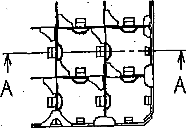

Figure 3.3.2(2) Support grid structure (2)

Table
3.3.2 Fuel rod design criteria and basic considerations |
Basic Considerations |
Design Criteria |
(1) Fuel Temperature |
|
Fuel temperature should not exceed the melting point of UO2, and UO2 with Gd. |
(2) Fuel rod internal pressure |
Avoid excessive rise of fuel temperature due to “thermal feedback” effect |
Internal pressure should not exceed the pressure which causes gap increase between pellet and cladding due to outward creep deformation of the cladding during normal operation |
(3) Cladding Stress |
Assure integrity of cladding during normal operation and abnormal transients during operation |
Cladding stress should be less than the strength of cladding |
(4) Cladding Strain |
Circumferential tensile strain* should be less than 1% |
|
(5) Periodical Cladding Strain |
Assure integrity of cladding for various design transients including load-follow operation and daily load following |
Periodical cladding strain should be less than design fatigue based on the concept of ASME Section III |