

can be contained inside the RCCV. Hie
design leak rate is 0.4% / day of the RCCV air volume at room
temperature and at the pressure of 0.9 time of the service peak
pressure.
The RHR system is designed to have functions for the following
operating modes: the low pressure core injection (LPCI) mode, the
primary containment vessel (PCV) cooling mode, the shutdown cooling
mode, the suppression pool (S/ P) cooling mode, and the fuel storage
pool cooling mode. Explanations of the LPCI and PCV cooling modes
are dispensed with here. (See Section 2.7 for them.)
Shutdown cooling mode
The shutdown cooling mode
is the most common mode in which the RHR system removes
decay heat after the reactor is shut down. In this mode, the RHR
takes the reactor water from the suction line of the primary loop
recirculation (PLR) system, and returns it into the reactor through
the discharge line of the PLR system after pressurizing it by the
pumps and cooling it by the heat exchangers. Part of the cooled
reactor water is sprayed from the head spray nozzle installed at the
top of the reactor pressure vessel (RPV) to cool the RPV head.
In an ABWR plant, the RHR system takes the reactor water from the
suction line of the RPV, and returns it through the injection line
for the LPCI mode after pressurizing it by the pumps and cooling it
by the heat exchangers. The RPV head is cooled by the reactor water
cleanup (CUW) system with non-contaminated water through its head
spray line.
The heat exchanger has a bypass line for controlling the RHR cooling
rate by adjusting its bypass flow rate. During normal plant
operations, the RHR is filled with the S/P water in the LPCI mode as
one of the emergency core cooling systems (ECCSs). Therefore, it is
necessary to clean up the system line and warm it up before changing
the operating mode to the shutdown cooling mode.
Since the RHR is not required to function as an ECCS when the
reactor pressure is below 0.95 MPa (gauge), the system can start its
cleaning, and is switched to this shutdown cooling mode, when the
reactor pressure becomes lower than 0.75 MPa (gauge).
S/P cooling mode
In the S/P cooling, mode,
the RHR system takes the S/P water and returns it to the S/P after
pressurizing it by the pumps and cooling it by the heat exchangers,
when the S/P water temperatures are raised.
Fuel storage pool cooling mode
In the fuel storage pool cooling mode, the RHR provides
supplementary cooling to the fuel storage pool water when necessary.
The skimmer surge tank outlet line is connected with the RHR pump
suction line. The RHR
system takes the fuel storage pool water through this line, and
returns water into the fuel storage pool after pressurizing and
cooling.
The purpose of the RHR system is to remove the decay and residual
heat during the above mentioned operating modes; it has the
following functions.
After the reactor is shut down, the RHR system cools the reactor
water to about 52°C within 20 hours by using both the turbine main
condenser and the feed water system, before the refueling operation
(shutdown cooling mode).
When the S/P water temperature rises during plant normal operations
due to safety relief valve (SRV) operations or reactor core
isolation cooling (RCIC) system operations, the RHR system cools
the S/P water (S/P cooling mode).
When the cooling capacity of the fuel pool cooling and cleanup
(FPC) system has been exceeded (for example, when all fuel rods in
the reactor are to be moved to the fuel storage pool), the RHR
system can back up the FPC system (fuel storage pool cooling mode).
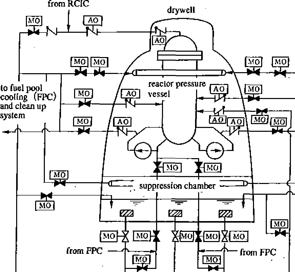
Figures 2.8.1 and 2.8.2 outline the RHR system for a 1100 MWe class
BWR and ABWR, respectively.
Hie heat exchangers in
these systems are cooled by the reactor building closed cooling
water system.
NSRA,
Japan
2-92
Reactor Auxiliary Systems
Residual Heat Removal (rhr) System
Operating modes
System functions and configuration
Chapter
2 Systems of BWR Nuclear Power Plants
T“l to
spent fuel pool cooling and filtering system (FPC)
reactor
building cooling water system - (RCW)
Z
reactor
building cooling water system (RCW)
Figure
2.8.1 Outline of the RHR system for the 1,100
MWe BWR
(FPC:fuel pool cooling and
clean up system) (CUW:reactor
waler clean up system) (RHR: residual heal removal system)
to FPC
from FPC
to
FPC to CUW
primary containment vessel
(PCV)
from
FPC
RHR pump
reactor
building
cooling
water
system
reactor
building
cooling
waler
system
RHR heal
cxhtfhger
RHR
heal
cxhangcr
from
feed waler
system (FDW)
RHR heal exhanger
Figure
2.8.2 Outline of the RHR system for ABWR
drywel
reactor
pressure
vessel
W-4-<e
pressure suppression =p
—=chamber.
• |F~ |
reactor building cooling water |
|
|
system |
|


2-93
NSRA,
Japan
Key components and
features
Basic specifications of RHR key components are
shown in
Table 2.8.1.
Pumps
The RHR system pumps are designed to have
the same capacity
as those used in the LPCI mode
described in Section 2.7. The
design conditions
of its net
positive suction head (NPSH) are
based on the
United States NRC Regulatory-
Guide 1.1. The RHR pumps are
designed for the
following severe conditions: the pressure
of the
S/P is atmospheric and the water temperature is
100
oC (saturated temperature) in a LOCA Since
the RHR pumps
require a very low NPSH, pit
barrel type pumps, which have
good performance
even at low NPSH, are used as the RHR pumps
in
the 1,100 MWe class standard BWR and ABWR
(Figure
2.8.3).
Heat exchangers
Heat exchangers are designed to satisfy the
requirements for
both the PCV spray mode (in
this mode, only one heat
exchanger is used for the
BWR, while two are used in the
ABWR) and the
shutdown cooling mode (in this mode, two
heat
exchangers are used for the BWR, while three
are
used in ABWR). See Section 2.7 for these two
RHR operating
modes.
Figure
2.8.3 RHR pump for 1,100
MWe
BWR
Table2.8.1
Basic specifications of the main
components of the RHR
system |
||
Pumps unit rated flow/head type |
3 about 1700m3/h @ about 95m vertical shaft multi stage type (pit barrel type pump) |
|
Heat Exchangers unit type |
2 U-tubc type (horizontal) |
|
Example of an ABWR |
||
Pumps unit rated flow/head type |
3 About 950m3/h @ about j 25m vertical shaft multi stage type (pit barrel type pump) |
|
Heat Exchangers unit type |
3 U-tube type (horizon taQ |
|
