Figure
2.3.10
Jet pumps
LPFL
nozzle
LPFL
sparger
HPCF
nozzle
fuel
assembly
react
or inte
mal
pomp
control
rod drive housing
steam
outlet nozzle (with flow limitter)
top
head sprayvent
nozzle
flange
steam
dryer
steam
separator
feed
water inlet
nozzte
feed
water sparger
core
shroud
control
rod
core
plate
reactor
pressure vessel
support
skirl
(
HPCF:
High pressure core flooder
LPFL : low pressure flooder
Figure
2.3,11 Cut-away view of an
ABWR reactor pressure vessel
In-core flux monitors guide tube
The in-core flux monitor
guide tubes extend from the in-core flux monitor housings
mounted on the RPV bottom head, provide partial support for the core
plate, and orient the in-core neutron flux monitors.
Channel box
The channel boxes that
encase each fuel assembly provide a channel for the coolant flow for
the fuel assembly. The boxes separate the cooling channel for fuel
rods from those for the control rods and in-core monitor guide
tubes. Four adjacent channel boxes form a guide channel for control
rods. In addition, the channel boxes provide rigidity of fuel
assembly and protect the fuel rods during their handling.
ABWR
In an ABWR, the conventional external recirculation system
(including jet pumps and recirculation pumps) is eliminated and
replaced by internal recirculation pumps installed inside the RPV.
Figure 2.3.11 shows the
internal structure of the
ABWR RPV. Key differences between an ABWR and a conventional BWR RPV
are as follows:
The conventional top grid made of stainless steel beams is replaced
by a machined grid made from a solid plate and it is attached to
the conventional upper shroud.
The moisture separator for the ABWR features a smaller pressure
drop than the conventional BWR, and also has a smaller outside
diameter. The height of the steam separator standpipe is also
shorter in an ABWR.
Because there is no
outside recirculation loop, the potential for core uncovering has
been eliminated analytically and the necessity of the high and low
pressure core injection sparger system has been eliminated also.
The reactivity control system of a BWR consists of control rods,
control rod drive system, and the standby liquid control (SLC)
system. During normal operation, reactivity is controlled by
controlling the neutron flux in the core by moving the control rods
that contain neutron absorbing materials into and out of the core.
Hie control rod drive
system
NSRA,
Japan
2-26

Incore monitor housing
Hpcf sparger top Fuel guide—
Reactivity control system
Chapter
2 Systems of BWR Nuclear Power Plants
consists of the control rod drive mechanisms and control rod drive
hydraulic system which insert or withdraw the control rods at a
speed required for normal operation. In an emergency, the control
rods are rapidly inserted into the core for a scram (rapid
shutdown).
The SLC consists of a borated water tank, pumps, test tank, piping,
valves, etc. The SLC is provided to insert negative reactivity to
the core for shut down by injecting borated water in case the
control rods cannot be inserted.
Brief descriptions of other systems are given below.
Control rod and control rod drive system
The control rods and the control rod drive system are designed to
the following policies:
The ejection speed of the control rods must be limited in order to
avoid rapid reactivity increase, even when the control rods drop
out of the core for any reason.
The control rods can be inserted into the core under the design
basis earthquake.
The control rod drive
system must be capable of rapidly inserting the control rods into
the core (scram) to prevent fuel failure during abnormal transients
and accidents. This functional capability must be secured even if
the power to the control rod drive system is lost.
All the control rods must be operable independently of each other
and a failure of one control rod or one control rod drive mechanism
must not affect the availability and function of the other control
rods.
Each control rod is supported by its own control rod drive
mechanism and the rod position is held by a positioning system.
The maximum withdrawal speed of the control rods is set at a value
allowing the operators to appropriately control the reactor power
in combination with their reactivity worth control.
In order to prevent a control rod ejection accident caused by a
failure of the control rod drive flange or housing, due
considerations must be given to the welding between the RPV bottom
head and the control rod drive housing. There should be a
sufficient margin against the maximum anticipated stresses and a
housing support structure should be used below the
control rod drives to prevent ejection of control rods from the
core, even when the control rod drive or the housing suddenly and
completely is breached.
Each of the control rods and control rod drive systems are
independently installed in the reactor vessel and hence, each of
them can be separately removed and repaired when necessary.
The control rods and the control rod drive system must be testable
periodically for their function to rapidly shut down the reactor.
The control rod and control rod drive system that are designed with
the above policies have the following specific structures.
Control
rod (CR)
Control rods consist
of neutron absorbing material for reactivity control and structural
materials. There are two types of control rods, namely, boron
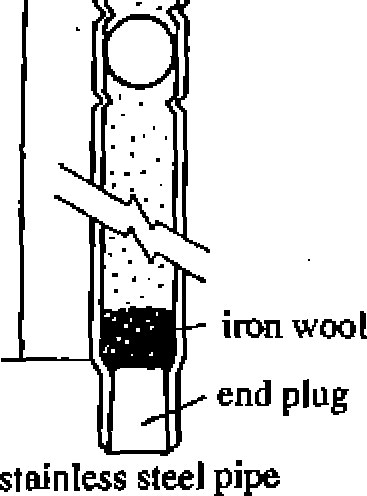
carbide control rods and hafnium control rods. A boron carbide
control rod, as shown in Figure 2.3.12, consists of numerous
stainless steel pipes filled with boron carbide powder (B4C,
a strong neutron absorber) that are housed in a cruciform sheath
made of thin stainless steel plates. Each control rod is positioned
in the space between four adjacent fuel assemblies, and a
substantial number of control rods are distributed uniformly in the
core at approximately 30 cm pitch.
A velocity limiter, a hydraulic structure with no moving parts, is
attached to the bottom of each control rod blade so that, even when
the control rod blade detaches from the coupling for any reason and
falls out of core due to its own weight from its stacked position in
the core, the falling speed of the control rod is limited to an
acceptable value. Figure 2.3.13 (1) shows the velocity limiter; it
is a parasol-shaped piston, able to move up and down with an
appropriate gap from the control rod guide tube. The parasol-shaped
velocity limiter has a small hydraulic resistance for rapid
insertion of the control rod (scram) and a large hydraulic
resistance against control rod drop out.
There are several types of hafnium control rods. An example is shown
in Figure 2.3.13 (2).
Hafnium plates are housed in a cruciform stainless steel case.
Figure 2.3.14 shows an example of
2-27
NSRA,
Japan
fuel
rod
sheath
roller |
Ioooooooo I oooooooo oooooooo oooooooo oooooooo oooooooo OOQOOOOO 3(00000000] |
roooooooo oooooooo oooooooo oooooooo oooooooo oooooooo oooooooo [oooooooo; |
QOQQQdbO OOOOOOOO OOOOOOOO OOOOOOOO 00000000 OOQOOOOO OOQOOOOQ [ooopoooo] |
fuel
assembly and host
channel
box
(neutron
absorber)
Figure
2.3.12 Cross section of a
control rod
Figure
2.3.13 (2) Hafnium control rod
Ball
check valve
Figure
2.3.13 (1) Boron carbide control rod
Core
pressure
Figure
2.3.14 Control rod for an ABWR
Coupling
spud
RPV
Filter
CRD
housing -
Thermal
sleeve
Buffer
Index
tube
Driving
piston
Seal
ring
Flange
Insertion
and
scram
Uncoupling
rod
Guide
cap
Collet
finger
Return
spring
Withdraw
Piston
tube
Seal
ring
Collet piston
Figure
2.3.15 Control rod drive
mechanism
NSRA,
Japan
2-28
![]()


Chapter
2 Systems of BWR Nuclear Power Plants
reactor
feed water system
reactor
water clean up system
from
oudd
cf
tDOfasge
<temiwrali?g
or
condensate
storage tank
(HCU)
scram
discharge volume
Figure
2.3.16 Control rod drive hydraulic system schematic drawing
a control rod for an ABWR, The ABWR control rod has no velocity
limiter. A control rod and its drive assembly are not separable
unless they are rotated by 45 degrees around the axis. In case a
control rod falls out of the core due to its own weight from its
stacked position in the core, it falls coupled with the hollow
piston of the control rod drive. The ABWR control rod drive limits
the control rod free drop velocity by a special mechanism to provide
large resistance against the control rod drop out
Control rod drive mechanism (CRD)
The CRD is a single hydraulic piston-type mechanism housed in the
control rod drive housing extended from the RPV bottom head, and is
attached to the bottom flange of the housing by bolting as shown in
Figure 2.3.15.
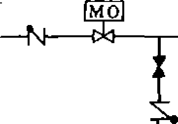
Control rod drive hydraulic control system
Figure 2.3.16 shows the control
rod drive hydraulic control system that operates the
control rod drives. Key components of the system include the control
rod drive water pumps, scram discharge volume, and hydraulic
control units
(HCUs). The HCUs
have various valves and an accumulator, and drive the control rods
for insertion/withdrawal or scram.
For a reactor scram, both the scram inlet and outlet valves of the
HCUs are opened, the accumulator pressure is transferred to the
bottom of the main drive piston and the bulk of coolant above the
piston is discharged into the scram discharge volume; these actions
give the control rods a strong acceleration for insertion into the
core for a reactor scram in less than a few seconds. If the
accumulator pressure drops below the reactor pressure for any
reason, the ball position of the ball check valve will automatically
change and the reactor pressure will be applied to the bottom of the
main drive piston to complete the reactor scram.
Standby liquid Control (SLC) System
The following design
policies are applied for the SLC
system.
The SLC system is completely independent from the control rod and
control rod drive system with sufficient redundancy for its
2-29
NSRA,
Japan