Chapter
2 Systems of BWR Nuclear Power Plants
At the top of the shroud, a shroud
head is flange-joined to the shroud, on which an array of standpipes
are welded with a steam separator unit at their top. Hie
shroud head forms the top core plenum, where mixtures of steam and
water from individual fuel assemblies are well mixed and homogenized
before being transferred to the steam water separators through the
standpipes,
Top guide and core plate
Hie top
guide is a grid-form structure, made of stainless steel
plate beams assembled at right angles to each other. It is welded to
the top of the core shroud and provides orientation and lateral
support for fuel assemblies. It supports the top ends of in-core
monitor guide tubes as well.
The core plate is
a perforated circular plate with beam supports made of stainless
steel, bolted to the bottom of the core shroud. Hie core plate
provides lateral support for control rod guide tubes, fuel
assemblies through fuel support pieces and in-core flux monitor
guide tubes (Figure
2.3.6).
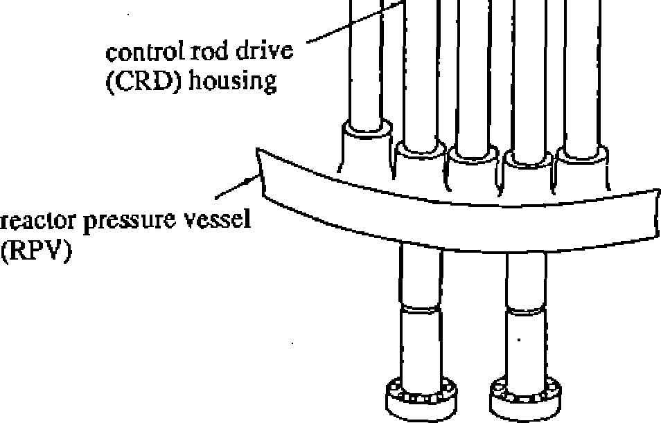
Control rod guide tube and fuel support piece
The control rod guide tubes
are supported by the control rod drive housings mounted
on the RPV bottom head; these tubes act as guide channels for the
control rod vertical movement in the core. Their top ends are
interlocked with the core plate. A fuel
support piece at the top of each control rod guide tube
bears the weight of four fuel assemblies as a group.
At the outermost periphery of the core where there are no control
rod guide tubes, fuel assemblies are supported by the support pieces
directly attached to the core plate.
Figure 2.3.6 shows the core and
the core support structure, whereas Figure 2.3.7 illustrates a fuel
support piece structure,
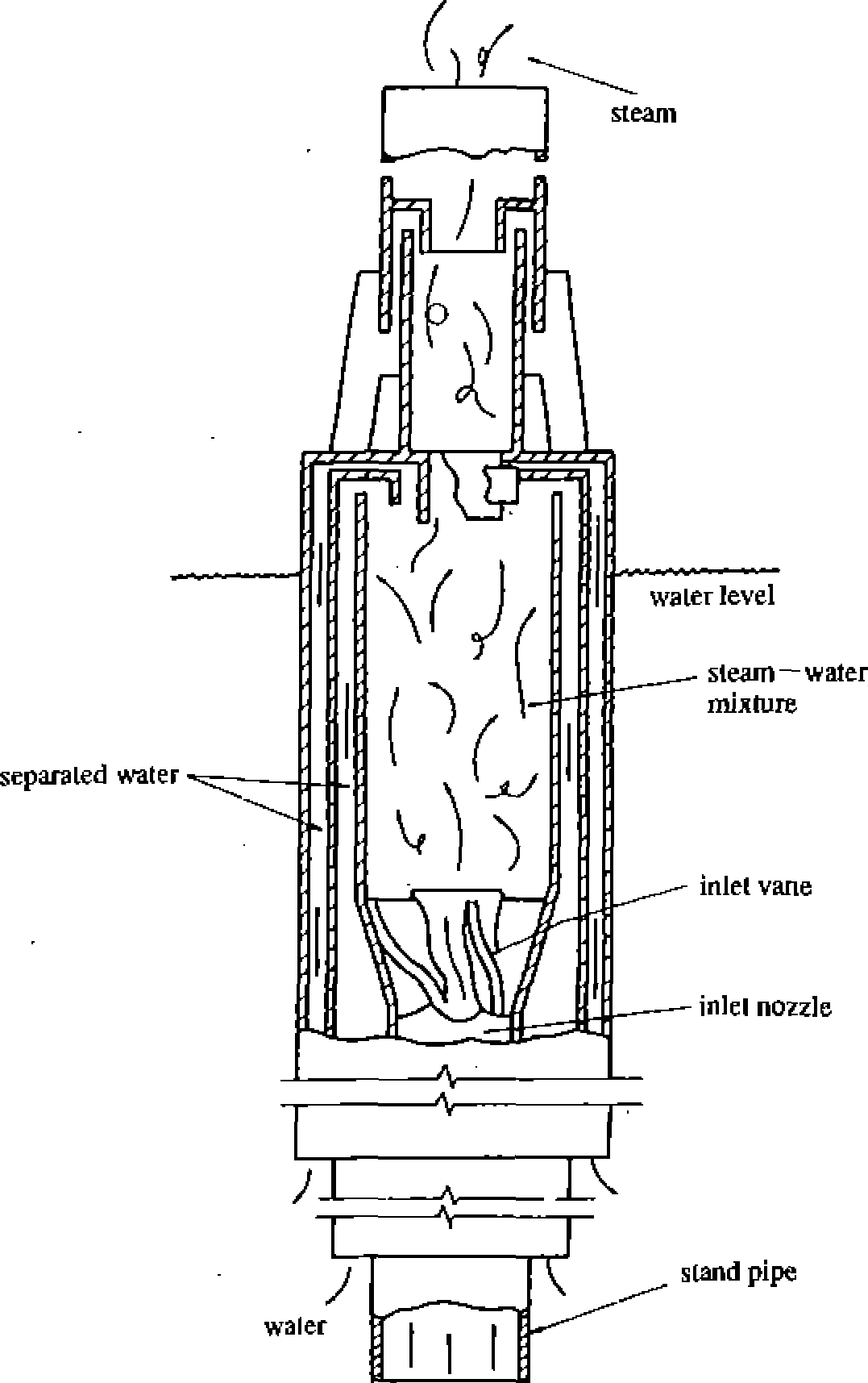
Other internal components a. Steam separator
The steam separator and
steam dryer assemblies separate steam from steam-water
steam
separator
shroud
head
stand
pipe
jet
pump diffuser
from
recirculation-
pump
core
shroud
jet
pump nozzle
suction
mixing
room
(throat)
upper
plenum
top
guide
core
plale
lower
plenum
to
recirculation pump
— reactor
pressure
Figure
2.3.5 Core shroud and coolant flow in RPV
top
guide
Figure
2.3.6 Core and lower core structures
2~23
NSRA,
Japan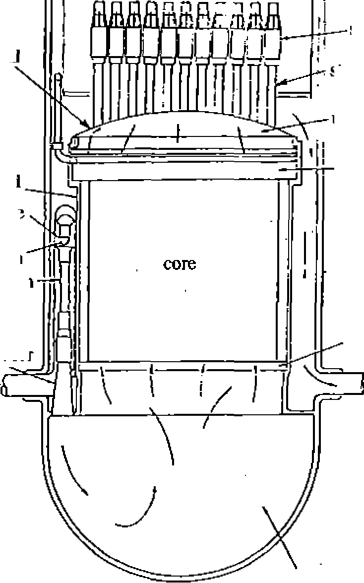
Vessel (rpv)


mixtures which flow out of the fuel assemblies. The separated steam
is conveyed to the turbine system and the water is returned to the
core through the recirculation annulus. The steam separator consists
of a large number of stainless steel centrifugal steam separator
units, laterally mounted on the shroud head. Figure 2.3.8 shows the
structure of a steam separator unit. The steamwater mixtures
from the core enter the bottom end of the steam separator units
through the top core plenum and the standpipes. Passing through the
inlet vane of the steam separator unit, the mixture gains a vortex
motion in which water is separated from steam by centrifugal force,
while the mixture flows up inside the tube.
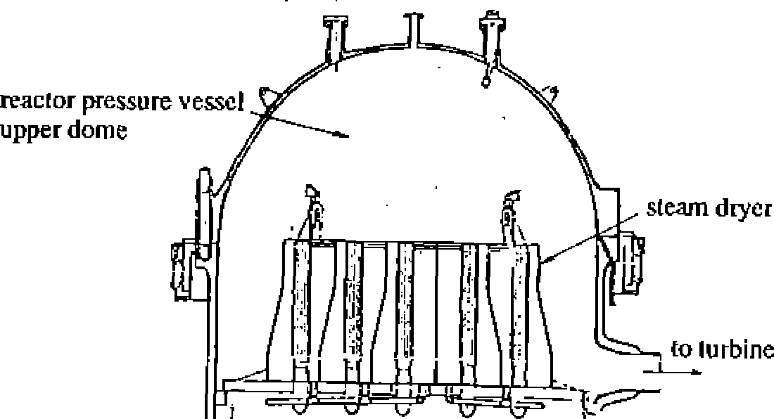
b. Steam dryer
As shown in Figure 2.3.9, a steam
dryer is an assembly of parallel corrugated stainless
steel plates. The steam flow changes its direction repeatedly while
it flows between the corrugated plates. With the changes in flow
direction, dispersed water drops collide with the stainless steel
plates and are removed from the steam. The
dried steam from the steam dryer is transferred to the turbine after
leaving the RPV via its upper dome and four main steam outlet
nozzles located below the vessel flange.
Jet pump
While external recirculation lines are provided for forced coolant
flow into the core (see Section 2.4.1) jet
pumps are utilized to reduce the coolant flow from the
vessel to the outside recirculation line. Twenty jet pumps are
located in the annulus between the reactor pressure vessel and the
core shroud as shown in Figure 2.3.10 and they are connected to the
recirculation flow to drive the coolant into the core for forced
convection. Saturated water from the steam separators and the steam
dryers above the core flows downward to the recirculation annulus
between the vessel and the core shroud, and is mixed with the feed
water from the feed water sparger. Part of the mixed coolant flow is
then taken from the vessel by the two completely independent
external circulation lines, pumped to a higher pressure by the (two)
recirculation pumps and discharged through the jet pumps nozzles at
high speed. The rest of the mixture is suctioned by the low pressure
zones at the jet pump nozzle outlets induced by the high speed
discharge of the recirculation water (driving fluid). The driving
flow and the suction flow are well mixed in the throat of jet pumps
before the mixture passes through
a diffuser (where the pressure is recovered), and then flows into
the
central region fuel support
piece
peripheral region fuel support
piece
Figure
2.3.7 Fuel support piece structure
NSRA,
Japan
2-24
Chapter
2 Systems of BWR Nuclear Power Plants
core. The coolant discharged from the jet pumps enters into the
lower plenum of the vessel (Figure 2.3.5), and flows into individual
fuel assemblies through the orifice at each fuel support piece shown
in Figure 2.3.7. The coolant is heated by the fuel elements while it
flows through the fuel assembly, and becomes a two-phase steam-
water mixture.
The core shroud, RPV lower
section and the jet pumps form an integrated container surrounding
the reactor core. This container is not directly connected to the
external recirculation piping. Therefore, even if the external
recirculation piping is breached, the core can be re-flooded by the
emergency core cooling system. The jet pumps (the throats of the jet
pumps) are installed at an elevation that allows for flooding the
core up to two-thirds of its height
Feed water sparger
A feed water sparger is
a circular header with elbow nozzles attached on the RPV inner
surface of the reactor vessel. It mixes the feed water entering the
vessel via feed water inlet nozzles and high temperature coolant
returning from the steam separators and steam dryers.
Core spray sparger
Core spray spargers are
provided to inject spray cooling water into the core inside the
shroud from the core spray system in an accident They are installed
near the top of the core shroud.
Reactor pressure vessel head spray nozzle
The head spray nozzle is located at the top of the RPV upper dome
where cooling water is injected from the shutdown cooling system
into the RPV upper dome in order to relief the residual pressure in
the vessel during the reactor shutdown.
Core differential pressure monitor and standby liquid injection
nozzle
The core differential
pressure monitor and the standby liquid injection nozzle are
a coaxial double pipe that penetrates the RPV into the reactor core.
In the core, the internal and external pipes separate, reaching
below and above the core plate to measure the pressure drop across
the core plate. The pipe reaching below the core plate is also used
for emergency injection of borated water into the core.
Figure
2.3.8 Moisture separator unit
Figure
2.3.9 Steam dryer
2-25
NSRA,
Japan