

Chapler
10
Quality Assurance (QA)
and analyzing their mutual relationships based on facts collected.
Developing, determining
and implementing corrective actions
The corrective actions are developed, determined and implemented
based on the causes of an occurrence.
In the decision of corrective actions, evaluation of the usefulness
of cost-effectiveness, etc., for the corrective action measures
considered is carried out to make appropriate actions about the
effects of the nonconformities.
In addition, when corrective actions are planned, decided and
carried out, reflections onto similar products (subsequent and
existing units) and to similar services (subsequent and existing)
are considered. This is called ” Horizontal expansion".
Besides the horizontal expansion stated above, the following actions
are also carried out, as appropriate;
Reflection onto quality assurance plans
Reflection onto designs,
procurement, manufacturing & installation, inspection &
test, the instruction manuals of operation & maintenance, etc.
Reflection onto facilities & equipment, etc.
Reflection onto education & training
Records of results of corrective actions taken and follow-up of
corrective actions
To show that the corrective actions were carried out reliably, the
results of the corrective actions taken are kept as records. It is
preferable that these records are added to the nonconforming report
or managed in an integrated fashion by clarifying the relationship
with the nonconforming report
Furthermore, it is important to carry out the corrective actions
reliably by confirming and following up the performance situations.
It is also important to improve the effectiveness of the quality
management system continuously by implementing the appropriate
actions if improvements are found in the corrective actions.
To prevent the occurrence of potential nonconformities beforehand,
it is important to
analyze the causes of nonconformities, etc., deeply, to expose the
potential causes, and to determine the actions to eliminate them.
This activity is generally called ”
Preventive action”. Important items in preventive actions are the
information collected for the potential nonconformities and for the
identification of their causes, and the analyses of their causes
based on facts. The information should include nonconforming
examples that have occurred both domestically and internationally.
Furthermore, regarding similar nonconformities and nonconformities
with a tendency to recur, it is also necessary to perform the root
cause analyses and to prevent the occurrence of the potential
nonconformities beforehand
The preventive actions are appropriate to the effect of the
potential problems. The
necessity of the preventive actions is judged in consideration of
the importance to nuclear safety. When the importance is low,
simplification of the action and a policy of not performing the
preventive actions are included as options.
When the preventive actions are judged as necessary as a result of
the consideration of the effects of potential problems, it is
necessary to establish the procedure manual which prescribes the
requirements for the following items and to carry out the preventive
actions reliably.
Determining the potential nonconformities and their causes
Analyzing information, identifying the potential nonconformities and
their causes
Evaluating the need for actions to prevent the occurrence of
nonconformities
Performing the evaluation based on the usefulness of the
cost-effectiveness, etc., for implementation of corrective actions
considered
Determining and implementing actions needed
Deciding the specific method for preventive actions and carrying it
out according to the procedure manual reliably
Records of results of action taken
Recording preventive action taken
Reviewing preventive action taken
Confirming the implementation status of all the above activities and
following them up.
10-33
NSRA,
Japan
Preventive Action
Appendixes
Appendix 1:
Chronology of Nuclear Power Plants
Appendix 2:
Typical BWR
Plant Specifications and Facilities
Appendix 3 : Typical PWR
Plant Specifications and Facilities
Appendix 4 : History of
Nuclear Technology in Japan and
Transition of Total
Generating Capacity of Nuclear Power Plants
Appendix 5 : Items of
Improvement and Standardization(I/S)
Project
for Light Water Reactor
-BWRs-
Appendix 6:
Items of Improvement and Standardization (I/S) Project
for Light Water Reactor
-PWRs-
Appendix 7 :
Key Specifications of BWR, PWR, ABWR
and APWR Plants
Appendix 8 : The Outline of
International Nuclear Event Scale (INES)Appendixes
NSRA,
Japan
NSRA,
Japan
JAPC’:
Japan Atomic Power Company
JPDR™:
Japan Power Demonstration Reactor
Appendixes
Appendix 1 Chronology of Nuclear Power Plants

Appendix
2 Typical BWR Plant Specifications and Facilities
(1)
Key specifications of BWRs Spec. |
BWR-1 |
BWR-2 |
BWR-3 |
BWR-4 |
BWR-5 |
|
||
GE design |
Japan improved |
ABWR |
||||||
Fuel type (Initial load) |
6x6 |
7x7 |
7x7 |
7x7 |
8x8 |
8x8 |
8x8 |
|
Average core power density (kW/t) |
31 |
34 |
41 |
51 |
51 |
51 |
44-51 |
|
Forced core cooling method |
External loops (3-5 loops) |
External loops (2 loops) |
RPV Internal pumps |
|||||
Pumps |
Pumps and jet pumps |
Pumps + 5-nozzle jet pumps |
||||||
Coolant flow control |
Motor-generator sets |
Flow control valves |
Motorgenerator sets |
Thyrister control |
||||
ECCS |
2-CS |
HPCI added |
LPCI added |
3-LPCI+HPCS+LPCS |
3-LPCI +2-HPCF +RCIC |
|||
Primary containment vessel type |
Dry spherical |
MARK-I |
MARK-I / II |
MARK-II |
Improved & standardized MARK-I / JI |
ABWR |
||
Steel self-standing |
Concrete / Steel |
Steel selfstanding | |
Reinforced concrete |
|||||
Note :
CS (Core spray system), HPCI (High pressure core injection
system), LPCI (Low pressure core injection System), HPCS (High
pressure core spray system), LPCS (Low pressure core spray
system), HPCF (High pressure core flooding system), RCIC (Reactor
core isolation cooling system)
Design
trend of BWR primary containment vessel in Japan
MARK
J PCV
(1970-1979) Tsuruga-1
(357
MWe) Fukushima
1-1
(460
MWe) Fukushima
1-2
(784
MWe) Fukushima
1-5 (784
MWe) (460MWe) |
MARK-I Modified (1987- ) Shimane-2 (820 MWe) |
MARK-H (1978-1985) Fukushima 1-6 (llOOMWfe) |
Hamaoka-1 |
Hamaoka-3 |
Fukushima 2-1 |
(540 MWe) |
(1100 MWe) |
(1100 MWe) |
Hamaoka-2 |
Hamaoka-4 |
Kashi wazaki |
(840 MWe) |
(1137 MWe) |
Kariwa-1 (1100 MWe) |
|
Onagawa2 |
Tokai-2 |
|
(825 MWe) Shika-1 (540 MWe) |
(1100 MWe) |
MARK-II
Modified (1984- ) FukusJiima
2-2,3,4
(1100
MWe)
Kashi
wazaki
Kariwa-2,3,4,5
(1100
MWe)
ABWRRCCV
(1996- ) Kashiwazaki
Kariwa-6,7
(1356
MWe)
Hamaoka-5
(138OMWe)
NSRA,
Japan
app.
—
4


Appendixes
Specifications
of typical PCVs for BWR |
MARK-1 |
MARK Imodified |
MARKU |
MARK- Ilmodified |
ABWR RCCV |
||
Design features |
|
Same as left |
■ Pressure suppression type •Steel selfstanding •Drywell: conical ■Suppression chamber: cylindrical •Vertical vent tubes |
Same as left |
•Pressure suppression type ■ Reinforced concrete
|
||
Approx, size |
Output |
460 MWe |
1100 MWe |
1100 MWe |
1100 MWe |
1300 MWe |
|
Diameter |
11m |
24 m |
26 m |
29 m |
29 m |
||
height |
34 m |
38 m |
48 m |
48 m |
36 m |
||
Volume |
Drywell volume |
4,240 m3 |
8,800 m3 |
5,700 m3 |
8,700 m3 |
7,400 m3 |
|
Suppression Chamber volume |
3,160 m3 |
5,300 m3 |
4,100 m3 |
5,700 m3 |
6,000 m3 |
||
Pool water volume |
2,980 m3 |
3,800 m3 |
3,400 m3 |
4,000 m3 |
3,600 m3 |
||
Max. operating pressure |
Drywell |
4.35 kg/cm2-g |
4.35 kg/cm2-g |
3.16 kg/cm2-g |
3.16 kg/cm2-g |
3.16 kg/cm2-g |
|
Suppression chamber |
4.35 kg/cm2-g |
4.35 kg/cm2 ■ g |
3.16 kg/cm2-g |
3.16 kg/cm2-g |
3.16 kg/cm2-g |
||
app.~5
NSRA,
Japan
(2)
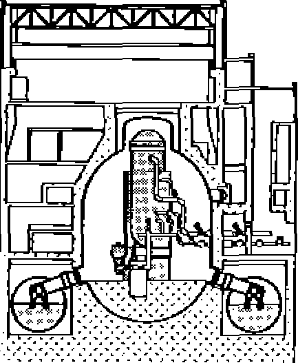
BWR emergency core cooling system
BWR—3
Outline Flow Chart of Emergency Core Cooling System
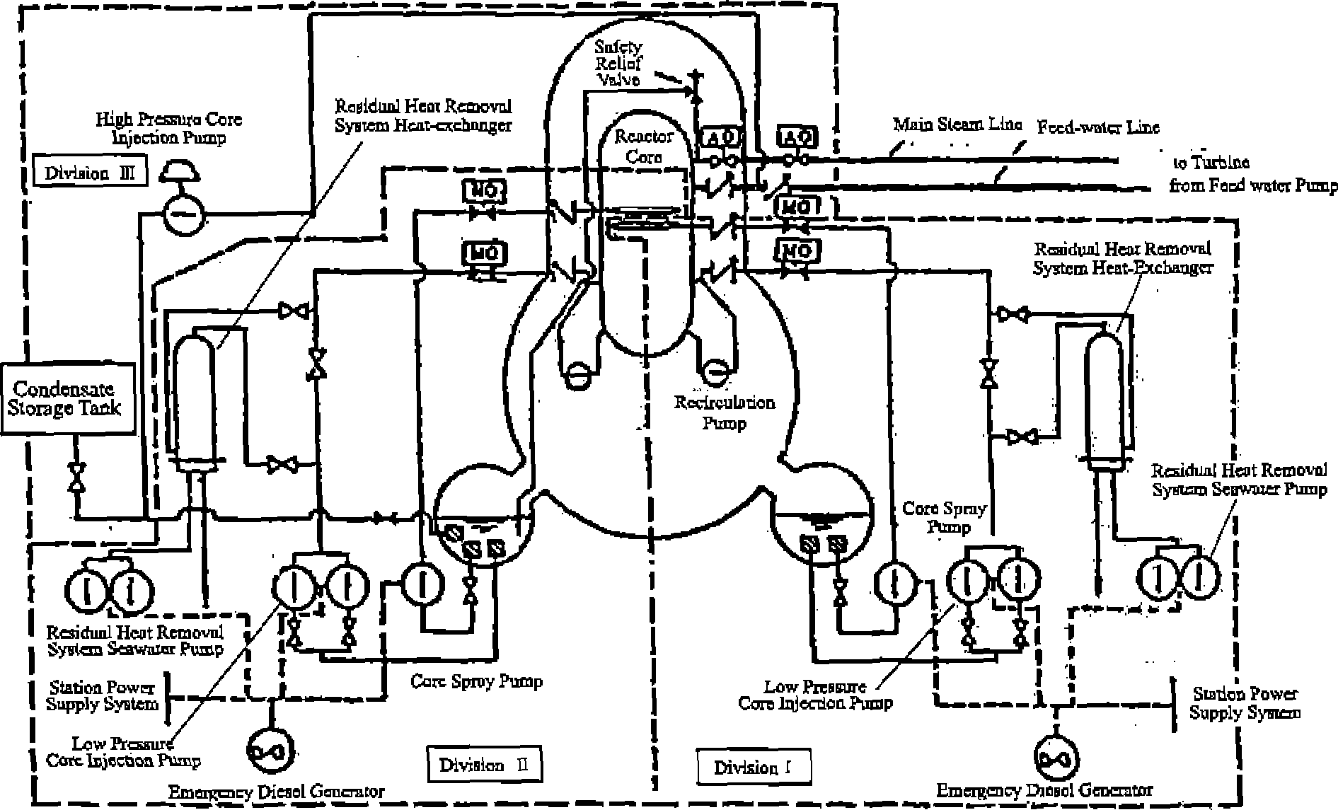
BWR—
4 Outline Flow
Chart of Emergency Core Cooling System
Rogidunl
Hom
Removal
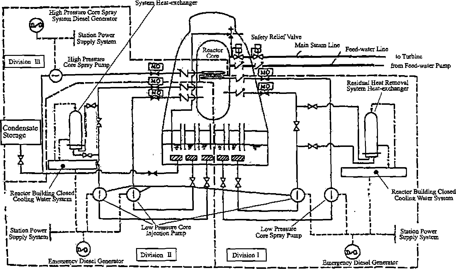
BWR—
5 Outline Flow Chart of Emergency Core Cooling System
ABWR
Outline Flow Chart of Emergency Core Cooling System

Appendixes
(3)
Evolution of BWR fuel major design specifications |
7x7 |
Improved 7x7 |
8x8 |
New 8x8 |
New 8x8 With Zr liner |
High burnup 8x8 |
Year |
1971 |
1974 |
1978 |
1982 |
1986 |
1991 |
Burnup (Mwd/t) |
21500 |
27500 |
27500 |
295000 |
33000 |
39500 |
for reload |
(approx.) |
(approx.) |
(approx.) |
(approx.) |
(approx.) |
(approx.) |
Pellet |
uo2 |
UO, |
uo3 |
UO, |
uo2 |
uo2 |
Dia. / Length (mm) |
12.4/22 |
12.1 /12 |
10.6/11 |
10.3 /11 |
10.3 /11 |
10.4 /11 |
Gd usage |
No |
Yes |
Yes |
Yes |
Yes |
Yes |
Cladding |
Zry-2 |
Zry-2 RCA *2 |
Zry-2 |
Zry-2 |
Zry-2 |
Zry-2 |
SRA*1 |
RCA*2 |
RCA *2 |
RCA*2 Corrosion resistance w/o autoclaving |
RCA*2 Corrosion resistance w/o autoclaving |
||
Thickness (mm) |
0.81, 0.90 |
0.94 |
0.86 |
0.86 |
0.86 |
0.86 |
No. of rods |
49 |
49 |
63 |
62 |
62 |
60 |
Water rod |
0 |
0 |
1 |
2 (large dia.) |
2 (large dia.) |
l(largedia.) |
Inti, press, (atm.) |
1 |
1 |
1 |
3 |
3 |
5 |
U blanket |
No |
No |
No |
No |
Yes |
Yes |
Spacer |
SUS, Inconel |
Zry-4 |
Zry4 |
Zry-4 |
Zry-4 |
Zry-4 |
X-750 |
Inco.X-750 |
Inco.X-750 |
Inco.X-750 |
Inco.X-750 |
Inco.X-750 |
|
|
(wire grid) |
(lattice) |
(lattice) |
(lattice) |
Qattice) |
(circ. cell) |
Design target |
Long fuel rod |
PCI countermeasure |
Lower thermal load (8x8 fuel Arrangement) Even power distribution (water rod) |
More thermal margin Better Uranium economy |
Higher performance |
Better economy & higher performance |
Note:
*
1SRA stands for
stress relief and annealed material *2 RCA stands for
re-crystallized and annealed material
7x7
IOOOOOOO’
OOOOOOO
ooooooo
OOOOQQO
OOOQOOO
QQQOOOO
OOOOOOO
8x8
OOOOOOOO
OOOOOOOO
OOOOOOOO
OOOOOOOO
ooooedoo
OOOOOOOO
COQOOOOO
0OOOOOOOJ![]()
■ One water rod
Reduced LHGR