

hydraulic units that cool the drive mechanisms, control the function
of the control rods and supply the pressure for insertion,
withdrawal and scram of the control rods are located near the
central story of the building and divided into two groups, one of
each side of the main steam pipe tunnel.
Among the reactor auxiliary systems, the reactor coolant clean-up
system filters and heat exchangers are located in an area behind a
thick concrete wall as they contain radioactive materials. Filter
element withdrawal hatches and lifting devices are placed above the
filter towers and the heat exchangers are provided with enough space
for pulling out their shell and movable shielding walls when
carrying out maintenance work. A similar arrangement is necessary
for the fuel pool water clean-up system and because of the high
radioactivity expected from this system, its equipment location is
concentrated in order to achieve short inter-connecting piping. The
residual heat removal system for the reactor consists of heat
exchangers and pumps, and since the heat exchangers need periodic
service, there must be enough space for pulling out the tubes and
shells of the horizontal heat exchangers and for disassembling,
making an overhaul inspection and and maintaining the head channel.
The installation height of the heat exchangers is determined by the
suction head of the pumps in the system.
The upper floor of the reactor building houses the standby gas
treatment system for the absorption and removal of radioactive
materials during an accident;
due consideration is given for minimizing the system’s discharge
duct length.
Since the main steam relief safety valves and control rod drive
mechanisms need periodic inspection and maintenance, a service room
with shielding is provided near the exclusive equipment hatch of the
PCV.
If the reactor building is a combined structure as discussed above,
radioactive waste storage and collecting tanks are located on the
lower floor, while the M-G sets for the PLR pumps are located on the
upper floor near the ground level for ease of disassembly and
maintenance of their rotating parts and carrying them in and out
during the periodic maintenance work. The area for these
non-radioactive equipment is separated from the radiation control
areas and personnel access control
is more relaxed.
The turbine building is
located near the reactor building in order to optimize the main
steam piping and feed water piping, based on consideration of the
length and thermal stresses and keeping good accessibility and
optimum cable length among the buildings.
There are various ways to arrange a reactor building and a turbine
building as shown in Figure 2.2.6, including the T-, L- and
I-arrangements. Both T- and I-arrangements
feature the reactor building perpendicular to the turbine shaft and
the I-arrangement places it
in parallel. One basis for deciding the final arrangement is the
protection philosophy towards a turbine missile in the site layout
planning.
A multi-unit site is generally adopted in Japan and
Figure
2.2.6 Main building arrangements
turbine
generator
in this case, the reactor building and the turbine building are
arranged as shown in Figure 2.2,7.
Some operating plants or plants under construction in Japan have
adopted either the slide-along arrangement or the mirror-image
arrangement; the choice was made with due consideration for the
location of the central control room and the overall view of the
plant which depends on individual site conditions.
It is generally said that the slide-along arrangement has better
accessibility than the mirror-image arrangement because of the
nearly identical location of the plant equipment and facilities in
the case of two adjacent main control rooms being in one independent
building for two units.
Because of radioactive steam flow from the reactor to the turbine in
a direct cycle BWR plant, the turbine facility becomes contaminated
with
NSRA,
Japan
2~
12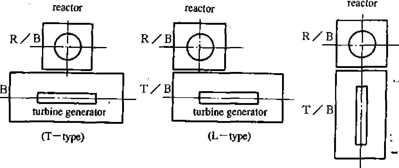
Turbine building
Chapter
2 Systems of BWR Nuclear Power Plants
reader reader
|
T--G |
T-G |
|
turbine generator |
turbine generator |
Slide-along
arrangement
(L—
type and T—
type)
reactor reactor |
R/B |
—— |
|
|
|
|
R/B |
|
||
|
|
V |
|
|
|
|
||||
T/B |
G-T |
|
T-G |
|
||||||
|
generator turbine |
generator turbine |
|
|||||||
Mirror-image
arrangement
(L—type
and T—type)
T=
turbine
G=
generator
radioactivity and its equipment and piping must be located in
shielded reinforced concrete structures and the steam turbine and
the steam intermediate stop valves must be covered by shielding of
steel plate or reinforced concrete. The main turbine and generator
are centrally located within the turbine building and they are
supported by reinforced concrete pedestals of high rigidity. Steam
condensers are located directly under the steam turbine and feed
water heaters, various pumps and condensate de-mineralizers are
located around the turbine pedestal and within the reinforced
concrete shielding. The steam turbine generator total length, the
main steam pipe routing at the front side of the steam turbine and
the pull out space of the generator rotor behind the generator are
the major factors that determine the length of the turbine building.
The turbine building operating floor width is determined based on
the space required to accommodate the disassembled equipment lay-
down area, work space and passage during the outage of the plant
Then, the horizontal dimension of the turbine building is determined
considering the required spaces for the HVAC system and other
auxiliary systems. The
depth of the building to the operating floor is determined by the
height of the condenser and turbine pedestal, and above the
operating floor, the height of the low pressure turbine rotor
casing, lifting height of this casing and the height of the overhead
traveling crane location
are the determining factors.
The turbine building is located near the ocean as it needs a large
quantity of sea water for cooling and in order to optimize the
length of the circulating water piping from the circulating pump at
the intake structure, it is placed nearer to the ocean in general.
The condenser tube top
height is normally set within a range where the siphoning effect of
the ocean tide may be utilized in order to minimize the running cost
of the large circulation water pumps.
Around the condensers, an ample space must be provided nearer to the
ocean side for the condenser tubing pull out, and auxiliary
equipment will be located nearer to the reactor building side. The
steam that exits from the turbine condenses back to water in the
condensers. The condensed water is pressurized by vertical
condensate pumps that effectively utilize the suction head near the
condensers and then it is transferred to the condensate
de-mineralizer for filtering out impurities. The condensate filter
has a hatch and a monorail above the de-mineralizer tower for ease
of filter element replacement. The
filtered condensate is re-heated in the feed water heaters which are
long cylindrical horizontal heat exchangers and they need a pull out
space for tubing replacement by cutting the cylindrical shells when
the need arises. Some of the feed water heaters are placed within
the condenser upper shell in order to utilize the condenser space,
and to optimize the steam drain and extraction piping and to
optimize the turbine building volume. The remainder of the feedwater
heaters are then located on the floors near the turbine pedestal and
reactor side. Because of high moisture contents in the steam that is
fed into the feedwater heaters, they are located on a floor below
the operating floor so that the extraction piping that goes through
the condenser upper shell will have a downward slope for ease of
draining. The pumps and feedwater heaters are fundamentally arranged
to minimize the condensate and feedwater piping, considering the
system flow, and to minimize the radiation to plant personnel by the
separation of high radiation areas and low radiation areas and the
shielding of the main passage for personnel with concrete walls.
The pumps, heat exchangers and blowers are arranged so that ample
working space close to their
2
—
13
NSRA,
JapanFigure.2.2.7 Main building arrangements (two-unit site)