Chapter
2 Systems of BWR Nuclear Power Plants
solid
base rock
Figure
2,2.1
Site plot plan conceptual model (cross section)
2-7
NSRA,
Japan

Figure 2.2.2 Overall plant layout of a bwr npp
about 159m
about 119m
reactor
building
reactor
building
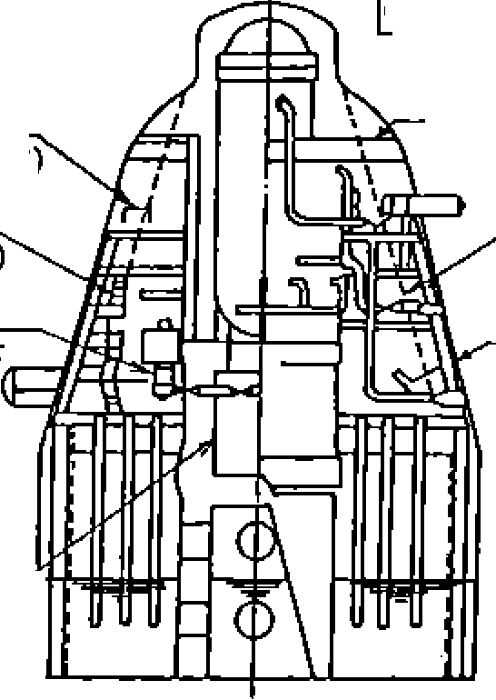
Figure
2.2,3
Typical equipment layout of a 1,100
MWe class plant
2-8
NSRA,
Japan
![]()

Chapter
2
Systems of BWR Nuclear Power Plants
floor of the reactor building near the turbine building
The reactor building houses
a reactor pressure vessel (RPV) which generates steam, a primary
containment vessel (PCV) which acts as the primary barrier against
release of radioactivity in
the event of an accident, pumps and heat exchangers for the safe
shutdown system, an emergency diesel generator system which provides
emergency power to the safety system components, a storage pool for
spent fuel assemblies, a water cleanup system for the reactor water
and the moisture-separator pit water, a standby gas treatment system
(SGTS) which prevents release of radioactive gases in the event of
an accident by keeping a negative pressure inside the reactor
building. The RPV is installed in the center of the building and it
is enclosed by the PCV while other equipment is located outside the
containment vessel. The PCV
is a steel self-standing structure fixed to the reactor building
foundation. Its outer surface is covered with a thick reinforced
concrete wall which acts as a biological shield. The reactor
building is a reinforced concrete structure from its foundations to
the operating floor and the building acts as the secondary
containment to confine radioactive materials. In order to ensure
that function, the building is kept at a negative pressure by the
heating, ventilating and air conditioning (HVAC) system.
Three different types of PCVs have been adopted at present including
that of the ABWR in Japan. Their features are summarized in Figure
2.2.4.
Among these, MARK-1 and
MARK- II containment vessels were introduced from the United States
and constructed as they were. However, based on the constructional
and operational experiences with BWR power plants in Japan,
improvements have been added to their original design and they have
been adopted as the Japanese Improvement and Standardization Program
design. Figure 2.2.5 compares the original design and the Japanese
Improvement and Standardization Program design.
Dimensions of the reactor building are determined by the size of the
PCV, reactor components layout and the operating floor lay-down
space. The size and layout of the bottom of the reactor building
are determined by the PCV or the suppression pool outside of the
biological shield for the Mark- I containment vessel, pumps of the
reactor safe shutdown system which utilize the corners of the
building effectively, and the emergency diesel generator system.
Dimensions of the upper operating floor are determined by the spent
fuel pool, temporary equipment pits, temporary spaces for
disassembled parts of the reactor system during the outage,
personnel passages, stairs and a large equipment hatch. The reactor
building horizontal cross section is nearly square. The height of
the building is determined by the total height of the PCV, the
required depth of water for shielding during transfer of spent fuel
assemblies from the reactor core, spent fuel cask lifting height and
the installation height of the overhead traveling crane. The
height of each floor and the number of stories in the building is
determined by the arrangement of auxiliary system components
optimizing the system flow from one floor to the next
Pumps for the emergency core cooling system (ECCS) that function to
cool the core in an accident as a safety system are located on the
lowest floor of the building just above the foundation in order to
effectively pump the suppression pool water. This system, including
piping and electrical cabling, consists of multiple trains separated
physically by concrete separation walls.
Access routes to each separate room are also separated from each
other for fire and flood protection. Assuming a very severe accident
condition where the external power is lost simultaneously with a
loss of coolant accident and a single failure occurs, the ECC
capability must be fulfilled. A vertical type core cooling pump is
used with an equipment hatch and lifting devices on the floor
above and there is ample space for disassembly and maintenance of
the pump.
The primary loop recirculation (PLR) pumps which recirculate reactor
coolant are located within the PCV with enough space for moving the
pump through a hatch from the reactor building. Also a provision
must be made for transporting out disassembled pumps for
maintenance. Control rod drive mechanisms are set in the housing
welded to the bottom head of the RPV and control rod drive
2-9
NSRA,
Japan
Reactor building
spent fuel pool.
reactor pressure vessel -
reactor building
(reactor secondary
shield)
access hatch
diaphragm floo
pressure
suppression
chamber access hatch
pit
for steam separator
reactor building
CRD repair room
reactor pressure vessel
vent
line
shield plug —
drywellhead
- biological shield wall
reactor shield wall
equipment hatch hydraulic
control unit
,
pressure suppression pool
(CRD: control rod drive
mechanism)
(1) MARK-I
shield block
drywell head
reactor primary
vent line
vacuum breaker
pit for steam dryer
and
steam separator
penetration
with
bellows
MSIV
shield
spent fuel pool
reactor
pressure vessel -
reactor primary shield -
diaphragm
floor _
reactor internal
pump
reactor building
(reactor secondary shield)
equipment
hatch
pressure
suppression
pool
(MSIV: main steam isolation
valve)
MSIV
PCV spray header
vacuum
breaker
pressure
suppression
pool
vent line
(PCV: primary containment
vessel)
pit
for steam dryer
and steam separator
PCV
spray header
MARK-2
(3) ABWR
Comparison chart |
Mark-I |
Mark-Il |
ABWR |
Height from foundation to PCV top |
Low |
High |
Low |
RPV height |
Low |
High |
Low |
Suppression chamber size |
Large |
Small |
Similar to Mark-II |
Seismic capability |
Slightly better |
Base |
Slightly better |
Building size |
Slightly larger |
Base |
Similar to Mark-II |
Figure
2,2.4 Conceptual design of
a 1,100 MWe class primary
containment vessel
NSRA,
Japan
2-
10


Chapter
2 Systems of BWR Nuclear Power Planls
Improvement of primary containment vesse (PCV) (section)
[Note]
broken line shows original design
drywell
major specifications of the
PCV |
ngmtd type |
original type |
-■riiSadu |
23.9m |
20.7m |
|
38.3m |
36.7m |
drags pnssst |
3.92kg/cmJg |
3.92kgfcm’g |
reaclor
shield wall
(keep
enough space
for
maintenance)
inside
space of RPV pedestal
(keep
enough
space for CRD, LPRM replacing)
(increase
of internal space)
cooler
(optimized
anamgemml)
stairs
(new
installation)
pipe whip structure
(optimized
arrangement)
recirculation pump
(keep
enough space 1
for
maintenance)
pressure
suppression
chamber
(increase
of inside diameter and height)
monorail
for SRV removal
(new
installation)
SRV
cany in / out
hatch
(new
installation)
MS
I V
(optimized arrangement)
stairs
(new installation) recirculation pump (keep enough space for
maintenance)
inside
space of RPV pedestal (keep enough
space for CRD, LPRM replacing)
(keep
enough space for maintenance) MS
I V
(keep
enough space
for maintenance)
major specifications of the
PCV |
hpmdtypc |
original type |
mi junta |
29m |
25.9m |
w* |
48m |
48 m |
iaipjisat |
2.85kg/cm’g |
2.85kg/cm’g |
monorail
(improvement)
major
valves
Improved MARK — I type PCV
Improved MARK — n
type PCV
Improvement
of layout inside of BWR primary containment vessel (in the stage
of improvement and standarization) |
|
increase operability decrease radiation dose |
|
Figure.
2.2.5 Comparison of original plant and improved and standardized
plant
2-
11
NSRA,
Japan